PHLPLLC30 WATT FM TRANSMITTER
Elettronika S.r.l.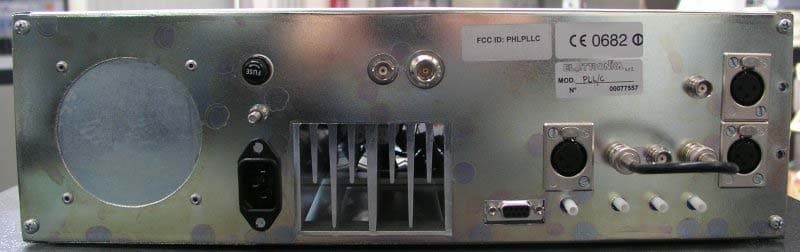
Click to zoom
Application Details
- Equipment Class
- TBC - Licensed Broadcast Station Transmitter
- Date of Grant
- Apr 10, 2005
- Application Purpose
- Original Equipment
- Date of Application
- Feb 24, 2005
- Equipment Note
- 30 WATT FM TRANSMITTER
- Frequency Range
- 87.90000000 - 108.00000000
- Company
- Elettronika S.r.l.
- Country
- Italy
Documents & Files
Document Text
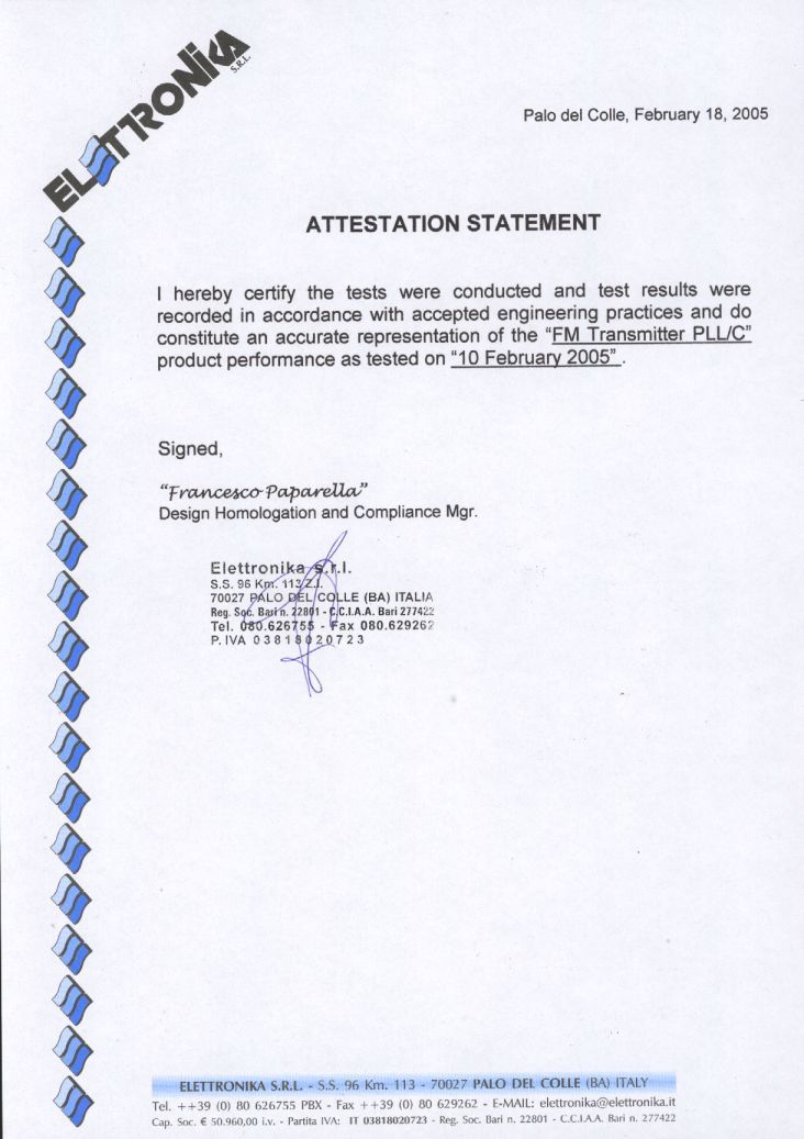
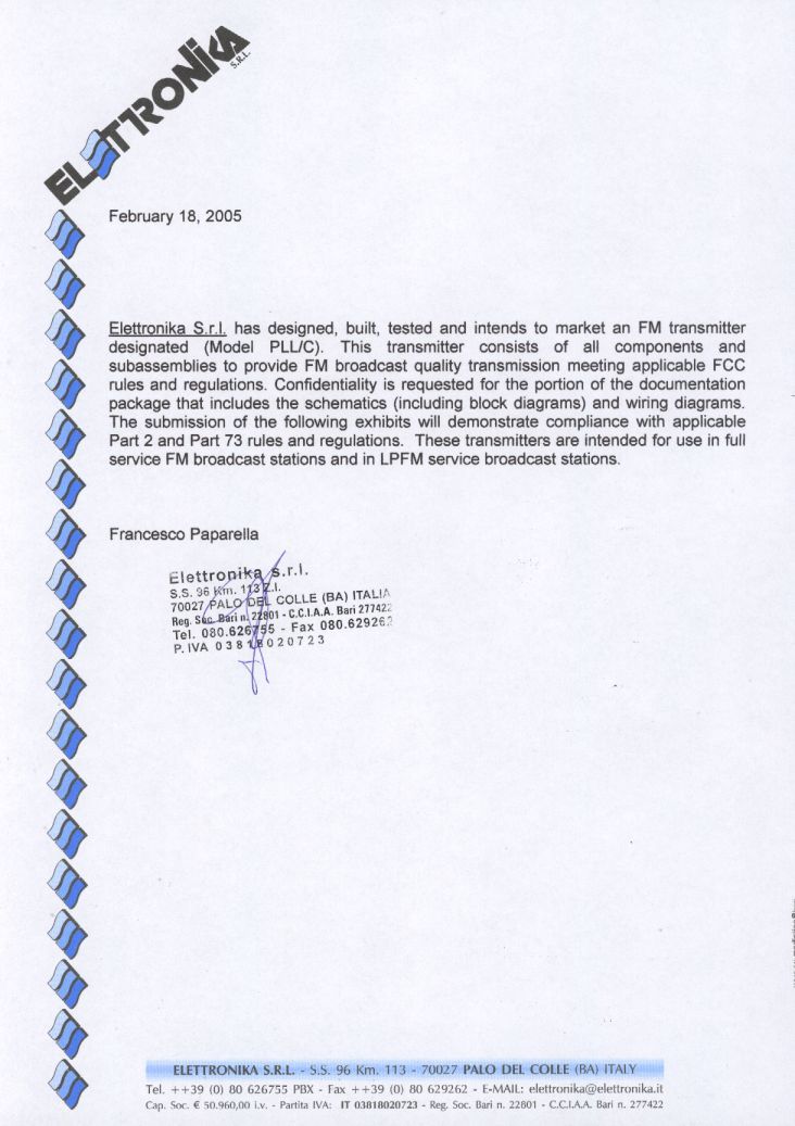
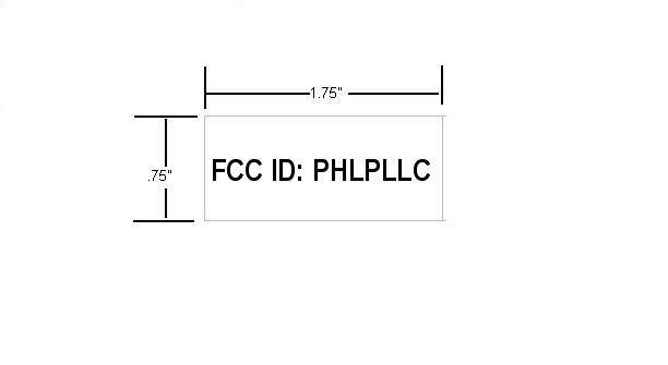
Text extracted from the exhibit documents filed with the FCC. Open a document above to read the original.
Block Diagram
BLOCK DIAGRAM Audio Input FM Modulator Bandpass Filter Low Voltage Power Supply RF Coupler Control & Power Metering Circuits Solid State Power Supply Solid state RF am p lifie r 3 0 wa tt s
External Photos
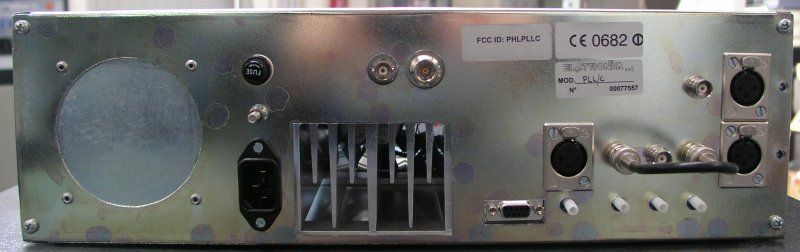
PLLC EXTERNAL CONSTRUCTION PHOTOGRAPHS PLLC FRONT VIEW PLLC REAR VIEW
Internal Photos
PLLC INTERNAL CONSTRUCTION PHOTOGRAPHS PLLC FRONT TOP VIEW PLLC TOP VIEW PLLC TOP RIGHT VIEW PLLC TOP LEFT VIEW PLLC LEFT REAR TOP VIEW PLLC RIGHT REAR TOP VIEW MAIN PC BOARD BOTTOM
Operational Description
March 4, 2005 Federal Communications Commission OET Equipment Authorization Branch Washington DC Dear Sir, This letter is to inform you that the operational description for the PLLC FM transmitter is contained in the user manual which has already been uploaded to the OET website. Sincerely, Greg Best President Greg Best Consulting, Inc. 9223 N. Manning Ave. Kansas City, MO 64157 816-792-2913
Parts List/Tune Up Info
February 26, 2005 Federal Communications Commission OET Equipment Authorization Branch Washington DC Dear Sir, This letter is to inform you that the parts list/tune up info for the PLLC FM transmitter is contained in the user manual which has already been uploaded to the OET website. Sincerely, Greg Best President Greg Best Consulting, Inc. 9223 N. Manning Ave. Kansas City, MO 64157 816-792-2913
Schematics
February 26, 2005 Federal Communications Commission OET Equipment Authorization Branch Washington DC Dear Sir, This letter is to inform you that the schematics for the PLLC FM transmitter are contained in the user manual which has already been uploaded to the OET website. Sincerely, Greg Best President Greg Best Consulting, Inc. 9223 N. Manning Ave. Kansas City, MO 64157 816-792-2913
Test Report
1 TEST REPORT ELETTRONIKA S.r.l FM TRANSMITTER TECHNICAL REPORT INTRODUCTION The following information is provided to verify the technical performance of the PLLC FM transmitter. The following information is supplied for FM broadcast service according to applicable portions of Part 2 and Part 73 of the FCC rules and regulations 1. Power Output Measurements as indicated by FCC Rule Part 2.1046 and. 2. Frequency stability measurements associated with variations in ambient temperature and with variations in line voltage as specified by 73.1545. 3. Demodulated Amplitude versus Frequency response measurements of the transmitter compliant with the Engineering charts identified in 73.333. 4. Occupied BW of the FM signal as specified by FCC Rule Part 73.297, 73.317, 73.319, 73.322, and 73.1570. 5. Measurement of conducted harmonics and spurs outside its assigned channel as specified by FCC Rule Part 73.317. 6. Measurement of cabinet radiation of spurs and harmonics as specified in FCC Rule 2.1053 and 2.1057. 7. Measurements of voltage and current to final amp stage as outlined in FCC Rule 2.1033. Measurements were conducted at power output levels of 30 watts and 5 watts and constitute the range of power for which type certification is sought. FIGURE 1--TEST EQUIPMENT CONFIGURATION The test equipment used for the measurements on the next few pages is listed at the back of this exhibit. All test equipment had been calibrated prior to the use of the equipment by the supplier of the test equipment. RF Power Output Stability vs Line Voltage The equipment was configured as shown in Figure 1. The loss through the RF output cable and directional coupler and attenuator was calibrated at the carrier frequency of 98 MHz. The audio generator was not energized. The transmitter was energized at room temperature at an initial power output of 30 watts. Power was read on the Bird 4391A Power Meter and a reference level was established on the Advantest R131 Spectrum Analyzer. The line voltage was varied from 94 volts to 126 volts using a variac to adjust Audio Generator (Part of Mod Analyzer) 6 dB Matrixing unit (Part of PLLC) PLLC Directional Coupler Power Meter Modulation Analyzer Spectrum Analyzer Voltage Measurement RF Load 2 the voltage. The test was repeated at an output power of 6 watts. The data is tabulated on the next page. RF Power Power Supply RF Power Power Supply 30W 94V ac 6W 94V ac 30W 110V ac 6W 110V ac 30W 126V ac 6W 126V ac RF Power Output Stability vs Temperature The equipment was configured as shown in Figure 1. The loss through the RF output cable and directional coupler and attenuator was calibrated at the carrier frequency of 98 MHz. The audio generator was not energized. The transmitter was energized at room temperature at a power output of 35 watts. Power was read on the Bird 4391A Power Meter and a reference level was established on the Advantest R131 Spectrum Analyzer. Next the temperature was varied from 0 C to +50 C. Data at the extreme temperature limits and at room temperature was recorded regarding power output. The transmitter was adjusted to 6 watts and the procedure was repeated. FRQUENCY STABILITY The equipment was configured as shown in Figure 1. The loss through the RF output cable and directional coupler and attenuator was calibrated at the carrier frequencies of 98 MHz. The audio generator was not energized. The transmitter was energized at room temperature at a power output of 30 watts. Power was read on the Bird 4391A Power Meter and a reference level was established on the Advantest R131 Spectrum Analyzer. The line voltage was varied from 94 volts to 126 volts. The output frequency was read on the spectrum analyzer. The results are tabulated below. RF Frequency Power Supply 98,0000010MHz 94V ac 98,0000010MHz 110V ac 98,0000010MHz 126V ac CONDUCTED EMISSION Two configurations have been considered: Stereophonic and Monophonic STEREOPHONIC MODE The pilot was set to 9% (6.75 kHz deviation) and 15kHz was injected into the Left (or Right) input with the main channel and the stereo channel at 28.5kHz deviation. The transmitter was energized at 30 watts RF output power and the conducted emission levels were recorded on the Advantest R131 Spectrum Analyzer. RF Power Temperature RF Power Temperature 35W 0°C 5W 0°C 35W 25°C 6W 25°C 36W 50°C 6W 50°C 3 As can be seen in the above graphs, in the stereophonic mode, the emissions meet the requirements as outlined in FCC Rule 73.317. The rule stipulates emissions between 120 kHz and 240 kHz from the carrier frequency are -25 dB or better, emissions between 240 kHz and 600 kHz from the carrier are -35 dB or better, and emissions greater than 600 kHz from the carrier are at least 43 + 10 log P o , or -67 dB referenced to the unmodulated carrier (top of the screen for these graphs). STEREOPHONIC MODE PLUS SCA In this case, an SCA channel has been added to the stereo channel. A frequency of 67 kHz is applied to the SCA input and its sub-carrier is modulated at 15% (11.15kHz). The 15 kHz applied to the left (right) channel is adjusted to obtain 70% modulation (52.5kHz). 4 As can be seen in the above graphs, the combined stereo and SCA channel emissions meet the requirements as outlined in FCC Rule 73.317. The rule stipulates emissions between 120 kHz and 240 kHz from the carrier frequency are -25 dB or better, emissions between 240 kHz and 600 kHz from the carrier are -35 dB or better, and emissions greater than 600 kHz from the carrier are at least 43 + 10 log P o , or -67 dB referenced to the unmodulated carrier (top of the screen for these graphs). Monophonic Mode For the Monophonic case, 15kHz has been applied to the Mono input with 85% modulation (63.75kHz deviation). 5 As can be seen in the above graphs, the monophonic mode emissions meet the requirements as outlined in FCC Rule 73.317. The rule stipulates emissions between 120 kHz and 240 kHz from the carrier frequency are -25 dB or better, emissions between 240 kHz and 600 kHz from t…
Text truncated - open the document above for the full version.
Test Report
1 TEST REPORT ELETTRONIKA S.r.l FM TRANSMITTER TECHNICAL REPORT INTRODUCTION The following information is provided to verify the technical performance of the PLLC FM transmitter. The following information is supplied for FM broadcast service according to applicable portions of Part 2 and Part 73 of the FCC rules and regulations 1. Power Output Measurements as indicated by FCC Rule Part 2.1046 and. 2. Frequency stability measurements associated with variations in ambient temperature and with variations in line voltage as specified by 73.1545. 3. Demodulated Amplitude versus Frequency response measurements of the transmitter compliant with the Engineering charts identified in 73.333. 4. Occupied BW of the FM signal as specified by FCC Rule Part 73.297, 73.317, 73.319, 73.322, and 73.1570. 5. Measurement of conducted harmonics and spurs outside its assigned channel as specified by FCC Rule Part 73.317. 6. Measurement of cabinet radiation of spurs and harmonics as specified in FCC Rule 2.1053 and 2.1057. 7. Measurements of voltage and current to final amp stage as outlined in FCC Rule 2.1033. Measurements were conducted at power output levels of 30 watts and 5 watts and constitute the range of power for which type certification is sought. FIGURE 1--TEST EQUIPMENT CONFIGURATION The test equipment used for the measurements on the next few pages is listed at the back of this exhibit. All test equipment had been calibrated prior to the use of the equipment by the supplier of the test equipment. RF Power Output Stability vs Line Voltage The equipment was configured as shown in Figure 1. The loss through the RF output cable and directional coupler and attenuator was calibrated at the carrier frequency of 98 MHz. The audio generator was not energized. The transmitter was energized at room temperature at an initial power output of 30 watts. Power was read on the Bird 4391A Power Meter and a reference level was established on the Advantest R131 Spectrum Analyzer. The line voltage was varied from 94 volts to 126 volts using a variac to adjust the voltage. The test was repeated at an output power of 6 watts. The data is tabulated on the next page. Audio Generator (Part of Mod Analyzer) 6 dB Matrixing unit (Part of PLLC) PLLC Directional Coupler Power Meter Modulation Analyzer Spectrum Analyzer Voltage Measurement RF Load 2 RF Power Power Supply RF Power Power Supply 30W 94V ac 6W 94V ac 30W 110V ac 6W 110V ac 30W 126V ac 6W 126V ac RF Power Output Stability vs Temperature The equipment was configured as shown in Figure 1. The loss through the RF output cable and directional coupler and attenuator was calibrated at the carrier frequency of 98 MHz. The audio generator was not energized. The transmitter was energized at room temperature at a power output of 35 watts. Power was read on the Bird 4391A Power Meter and a reference level was established on the Advantest R131 Spectrum Analyzer. Next the temperature was varied from 0 C to +50 C. Data at the extreme temperature limits and at room temperature was recorded regarding power output. The transmitter was adjusted to 6 watts and the procedure was repeated. FRQUENCY STABILITY STABILITY VERSUS LINE VOLTAGE The equipment was configured as shown in Figure 1. The loss through the RF output cable and directional coupler and attenuator was calibrated at the carrier frequencies of 98 MHz. The audio generator was not energized. The transmitter was energized at room temperature at a power output of 30 watts. Power was read on the Bird 4391A Power Meter and a reference level was established on the Advantest R131 Spectrum Analyzer. The line voltage was varied from 94 volts to 126 volts. The output frequency was read on the spectrum analyzer. The results are tabulated below. RF Frequency Power Supply 98,0000010MHz 94V ac 98,0000010MHz 110V ac 98,0000010MHz 126V ac STABILITY VERSUS TEMPERATURE The equipment was configured as shown in Figure 1. The loss through the RF output cable and directional coupler and attenuator was calibrated at the carrier frequency of 98 MHz. The audio generator was not energized. The transmitter was energized at room temperature at a power output of 30 watts. Power was read on the Bird 4391A Power Meter and a reference level was established on the Advantest R131 Spectrum Analyzer. The temperature was varied from -30 °C to +50 °C. The output frequency was read on the spectrum analyzer and recorded at each data point after the temperature was allowed to stabilize at that point. FREQUENCY TEMPERATURE 98.0000030 MHz -30°C 98.0000029 MHz -20°C 98.0000026 MHz -10°C 98.0000011 MHz +10°C 98.0000010 MHz +20°C 98.0000013 MHz +30°C 98.0000016 MHz +40°C 98.0000023MHz +50°C RF Power Temperature RF Power Temperature 35W 0°C 5W 0°C 35W 25°C 6W 25°C 36W 50°C 6W 50°C 3 CONDUCTED EMISSION Two configurations have been considered: Stereophonic and Monophonic STEREOPHONIC MODE The pilot was set to 9% (6.75 kHz deviation) and 15kHz was injected into the Left (or Right) input with the main channel and the stereo channel at 28.5kHz deviation. The transmitter was energized at 30 watts RF output power and the conducted emission levels were recorded on the Advantest R131 Spectrum Analyzer. 4 As can be seen in the above graphs, in the stereophonic mode, the emissions meet the requirements as outlined in FCC Rule 73.317. The rule stipulates emissions between 120 kHz and 240 kHz from the carrier frequency are -25 dB or better, emissions between 240 kHz and 600 kHz from the carrier are -35 dB or better, and emissions greater than 600 kHz from the carrier are at least 43 + 10 log P o , or -67 dB referenced to the unmodulated carrier (top of the screen for these graphs). STEREOPHONIC MODE PLUS SCA In this case, an SCA channel has been added to the stereo channel. A frequency of 67 kHz is applied to the SCA input and its sub-carrier is modulated at 15% (11.15kHz). The 15 kHz applied to the left (right) channel is adjusted to obtain 70% modulation (52.5kHz). 5 As can be seen …
Text truncated - open the document above for the full version.
Contact Information
Applicant
Francesco Paparella(Design Omologation and Compliance Mgr)
Technical Contact
GREG BEST CONSULTING, INC.GREG BEST
[email protected]816-792-2913
9223 N. MANNING AVENUE · KANSAS CITY, Missouri · United States
Technical Specifications
| # | Rule Parts | Frequency Range | Power Output | Emission | Tolerance |
|---|---|---|---|---|---|
| 1 | 73 | 87.9 MHz - 108 MHz | 30 W | 300KF8E | 1000.0000000000 Hz |
Other Applications from Elettronika S.r.l.
PHLTXUD1000A
Jul 07, 20101000 W ATSC Transmitter
Equipment Class
TBC - Licensed Broadcast Station Transmitter
PHLTXUD3000A
Jun 17, 20103000 Watt ATSC Transmitter
Equipment Class
TBC - Licensed Broadcast Station Transmitter
PHLTXUD2000A
Jun 09, 20102000 Watt ATSC Transmitter
Equipment Class
TBC - Licensed Broadcast Station Transmitter
PHLMIZAR30
Jul 01, 200830 Watt FM Broadcast Transmitter
Equipment Class
TBC - Licensed Broadcast Station Transmitter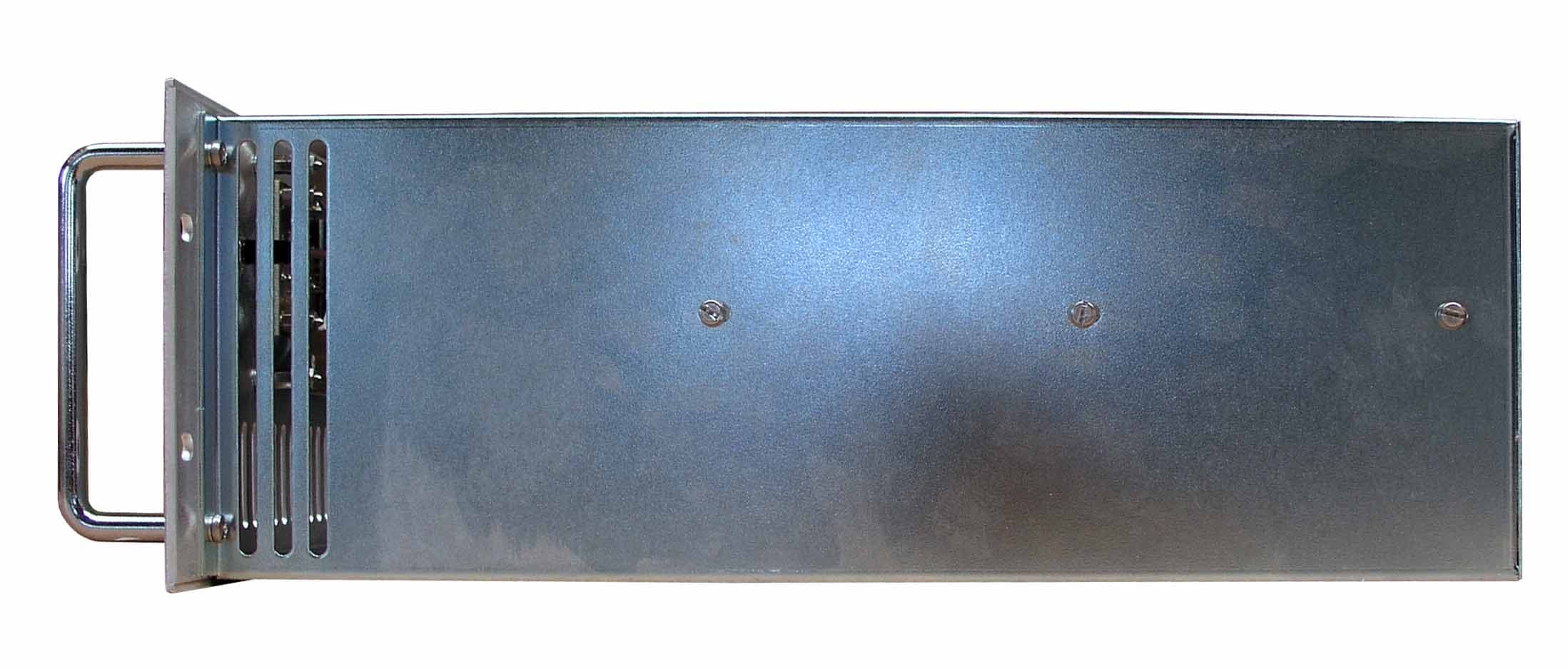
PHLMIZAR300
Jul 01, 2008300 Watt FM Broadcast Transmitter
Equipment Class
TBC - Licensed Broadcast Station Transmitter