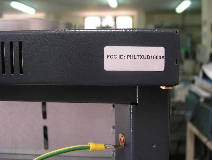
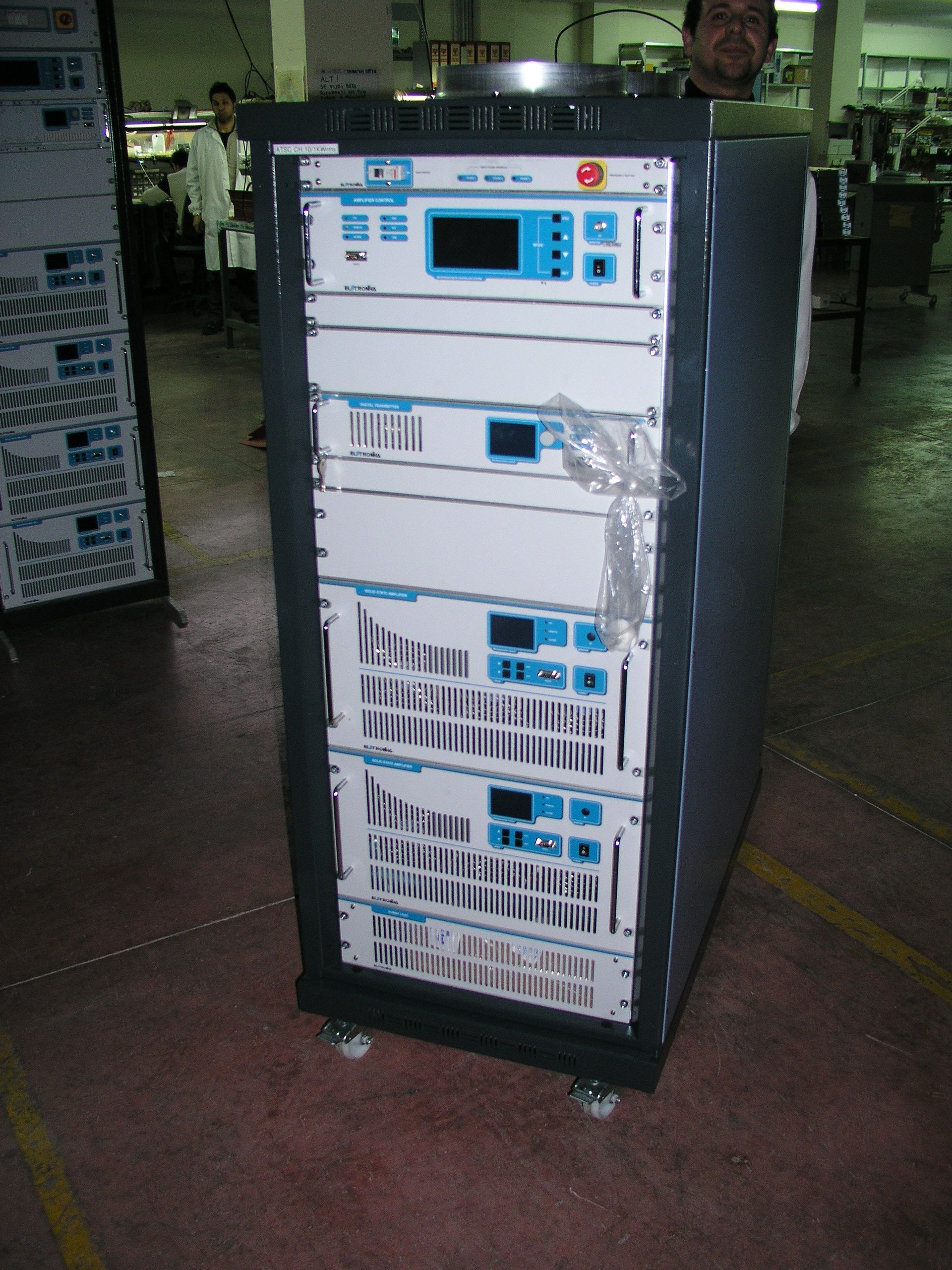
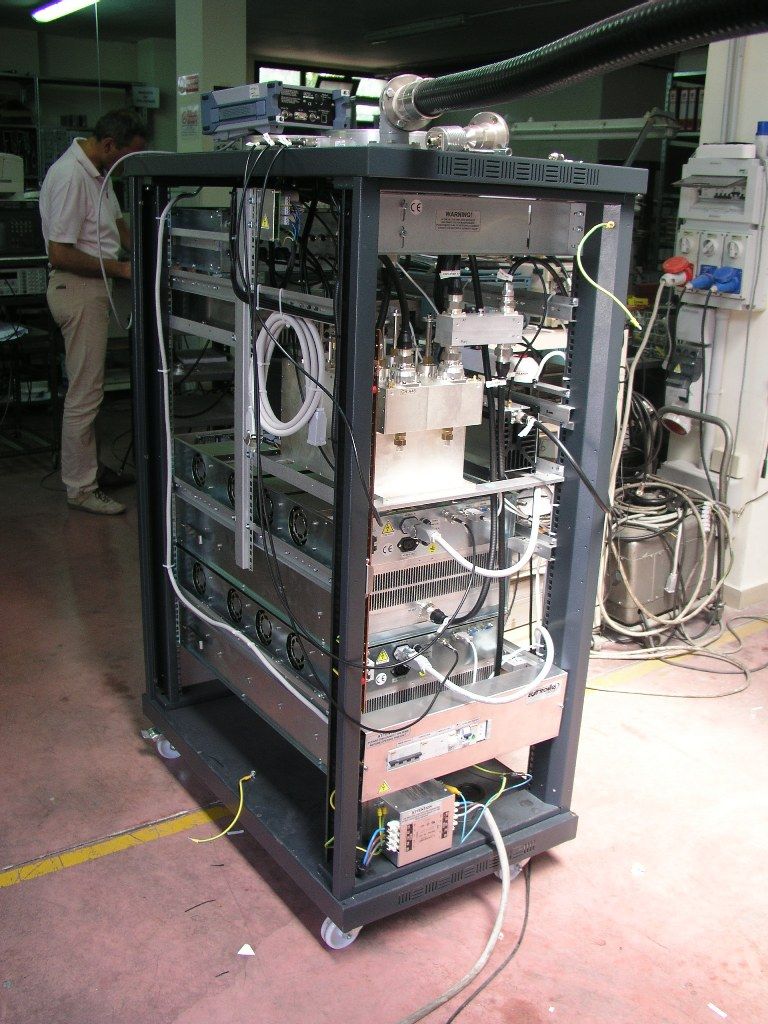
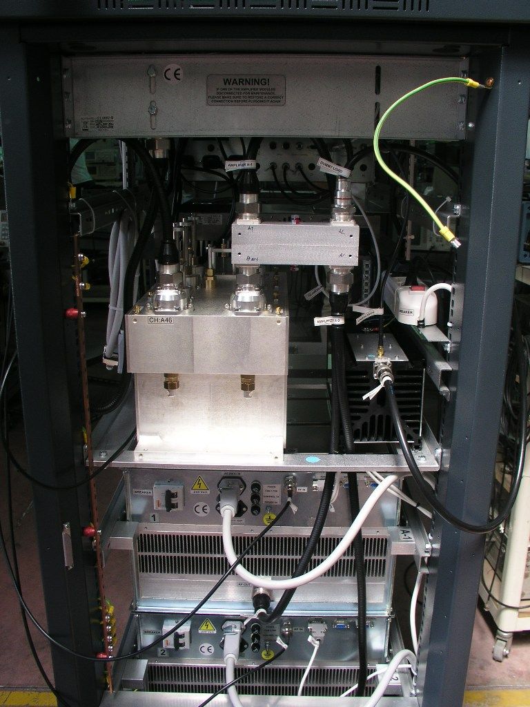
PHLTXUD1000A1000 W ATSC Transmitter
Elettronika S.r.l.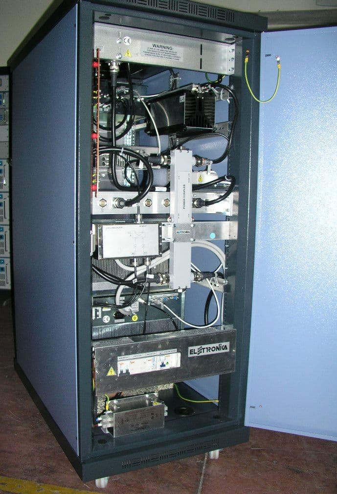
Click to zoom
Application Details
- Equipment Class
- TBC - Licensed Broadcast Station Transmitter
- Date of Grant
- Jul 07, 2010
- Application Purpose
- Original Equipment
- Date of Application
- Feb 21, 2010
- Equipment Note
- 1000 W ATSC Transmitter
- Frequency Range
- 614.00000000 - 806.00000000
- Company
- Elettronika S.r.l.
- Country
- Italy
Documents & Files
Document Text
Text extracted from the exhibit documents filed with the FCC. Open a document above to read the original.
Users Manual
TXUD1000/ATSC UHF TV Transmitter CODEAPT205L/DIGTITLETXUD1000/ATSC UHF TV TRANSMITTERREV 1DATE03/08/09 SS 96 Km 113 70027 Palo del Colle (Ba) ITALY Tel. +39 (0)80 626755 Fax +39 (0)80 629262 E-mail: [email protected] Web site: http://www.elettronika.it Registration number: IT-17686 Registration number: IT-24436 3 WARNING The apparatus described in this manual has been designed and manufactured with devices to safe- guard the users. In any case it is recommended that during any operation of installation, maintenance, miscellaneous interventions and calibrations requiring the apparatus to be switched on, THE USER TAKES ALL THE PRECAUTIONS AGAINST INCIDENTS It is required to use the proper clothes and protection gloves in order to prevent damages from inci- dental contacts with high-voltage parts. The manufacturer declines every responsibility in case the recommendations above are not followed. IMPORTANT The component lists attached to the relevant electrical diagrams indicate for each item the reference, the description and the type normally used. The Elettronika S.r.l. though reserves the right to use or supply as spare parts components with equivalent characteristics but of a different type, assuring anyway the optimal work of the apparatus in accordance with the specifications. The enclosed monographs are solely owned by Elettronika S.r.l. The use of anything enclosed in this technical manual without explicit authorization given by Elettronika S.r.l. will be prosecuted by the law. The data and technical characteristics of the apparatus described in this manual are not compelling for the manufacturer. The Elettronika S.r.l. reserves the right to make, without previous notice, modifications or updates in order to improve the quality of the product. The general conditions of supply and sale are described in the contracts. The delivery time are in accordance with the products and quantities ordered. 4 Summary of warranty We, ELETTRONIKA S.r.l., SS096 Km 113 Z.I. PALO DEL COLLE (BA) ITALY, warrant to the ORIGINAL PURCHASER of a NEW product, for a period of one (1) year from the date of purchase by the original purchaser (the “warranty period”) that the new ELETTRONIKA product is free of defects in materials and workmanship and will meet or exceed all advertised specifications for such a product. This warranty does not extend to any subsequent purchaser or user, and automatically terminates upon sale or other disposition of our product. Items excluded from this ELETTRONIKA warranty We are not responsible for product failure caused by misuse, accident, or neglect. This warranty does not extend to any product on which the serial number has been defaced, altered, or removed. It does not cover damage to loads or any other products or accessories resulting from ELETTRONIKA product failure. It does not cover defects or damage caused by use of unauthorized modificstions, accessories, parts, or service. What we will do We will remedy any defect, in material or workmanship (except as excluded), in our sole discretion, by repair, replacement, or refund. If a refund is elected, then you must make the defective or malfunctioning component available to us free and clear of all liens or other encumbrances. The refund will be equal to the actual purchase price, not including interest, insurance, closing costs, and other finance charges less a reasonable depreciation on the product from the date of original purchase. Warranty work can only be performed at our authorized service centers or at our factory. Expenses in remedying the defect will be borne by ELETTRONIKA, including one-way surface freight shipping costs within the United States. (Purchaser must bear the expense of shipping the product between any foreign country and the port of entry in the United States and all taxes, duties, and other custom’s fee(s) for such foreign shipments). How to obtain warranty service You must notify us of your need for warranty service not later than ninety (90) days after the expiration of the warranty period. We will give you an authorization to return the product for service. All components must be shipped in a factory pack or equivalent which, if needed, may Desclaimer of consequential and incidental damages You are not entitled to recover from us any consequential or incidental damages resulting from any defect in our product. This includes any damage to another product or products resulting from such a defect. Warranty alterations No person has the authority to enlarge, or modify this warranty. The warranty is not extended by the lenght of time for which you are deprived of the use of the product. Repairs and replacement parts are provided under the terms of this warranty shall carry only the unexpired portion of this warranty. Design changes We reserve the right to change the design of any product from time to time without notice and with no obligation to make corresponding changes in products previously manufactured. Legal remedies of purchaser There is no warranty which extends beyond the terms hereof. This written warranty is given in lieu of any oral or implied warranties not contained herein. We disclaim all implied warranties, including without limitation any warranties of merchantability or fitness for a particular purpose. No action to enforce this warranty shall be commenced later than ninety (90) days after expiration of the warranty period. Warranty for electronic tubes The warranty applied for electronic tubes is the one given by the manufacturer of the tube. In the event that the product shows anomalies within the deadline of the validity of the warranty given by the manufacturer of the product itself, the buyer will have to return it to the seller with the needed documents and the written description of the defect. The seller will ship the broken tube to the manufacturer in order to effect the necessary technical tests to find out the cause of the anomaly. Meanwhile the buyer of the tube wh…
Text truncated - open the document above for the full version.
Users Manual
76 LDMOS UHF SERIES MEDIUM POWER TV AMPLIFIER User’s manual 77 This page is intentionally blank 78 Section 1 - Information Contents: 1.1 Description 1.2 Main Features 1.3 Technical characteristics 1.4 Front panel 1.5 Rear panel Rear connections 79 1.1 DESCRIPTION The amplifier belongs to the Medium Power Amplifier products family of Television Amplifiers fully in solid state LDMOS technology. These TV Amplifiers operate in the UHF Band with Common amplification process (separate amplification available) of the Video and Audio carriers. This Amplifier family has been designed to offer to the customer high performances, high reliability and greater simplicity in its operation and maintenance procedures. The Video and Audio signal processing is provided for all TV Standards and all types of Audio applications (Mono & Dual Sound - NICAM) together with the different colour systems such as PAL - NTSC - SECAM. Thanks to the amplitude and phase and non linearity pre-correction circuit, it is possible to cancel the distortions in the output stage, thus cutting down the operating costs. Due to the common amplification design, the transmitter is easily upgradeable to any digital TV standard: DVB-T, DVB-H, DMB-T, ATSC. It is only necessary to replace the modulator and the RF output band pass filter, all the other components are used without any change. The cooling system is fully contained into the amplifier, and it is based on forced air flow. A powerful and very low acoustic noise blower is used. A front panel air dust filter is available, sized in order to enable easy replacement. The user interface is based on a graphics display, where all the parameters are showed. A detailed log of events and alarm help the maintenance of the system. The unit can be fully controlled in REMOTE mode via PC direct-link or via PSTN, GSM or Ethernet networks by means of Elettronika Remote Control System. The system can be easily upgraded with dual drive option. Besides, the transmitter can be easily integrated in a 1+1 or more complex N+1 redundancy configurations. 1.2 MAIN FEATURES - LDMOS Technology; - Forced-air cooling system; - Analog and Digital input signal; - High efficiency; - Wired and serial remote control (RS232 or RS485); - All voltages and currents available on display; - Output filter included. MEDIUM POWER TV AMPLIFIER SERIES 80 1.3 TECHNICAL CHARACTERISTICS RF SECTION Analog Operation Frequency Range ........................................................................................................................................................... UHF Output Power (±0.5dB)...............................................................................................................................................1300W Amplification Class.......................................................................................................................................................... AB Gain (±2dB)....................................................................................................................................................................28dB Technology.............................................................................................................................................Solid State LDMOS RF Input Connector ................................................................................................................................................ N Female Impedance....................................................................................................................................................................... 50Ω RF Output Connector (Amplifier / Rack)........................................................................................... 7/16” Female / EIA 7/8” Impedance....................................................................................................................................................................... 50Ω Digital Operation Frequency Range ........................................................................................................................................................... UHF Digital Output Power (DVB-T)............................................................................................................................. 300W RMS Digital Output Power (ATSC)...............................................................................................................................500W RMS DVB-T Modes.........................................................................................................All the modes listed in ETSI EN 300 744 DVB-T MER.......................................................................................................................................................> 33dB RMS DVB-T Shoulders Attenuation (After non-critical mask cavity filter) ................................................................> 40dB RMS DVB-T Output Spectrum.............................................................................................................Compliant ETSI EN 300 744 ATSC Symbol Rate......................................................................................10.76MBaud/s (Compliant to ATSC Doc. A/53) ATSC SNR.........................................................................................................................................................> 27dB RMS ATSC Shoulders Attenuation (After simple mask cavity filter ref. total output power) .....................................> 46dB RMS ATSC Output Spectrum ......................................................................................................... Compliant to ATSC Doc. A/64 REMOTE CONTROL SECTION Parallel Interface...........................................................................................................................ON/OFF, Alarms, Interlock Serial Interface.................................................................…
Text truncated - open the document above for the full version.
Users Manual
ATSC TV Digital Transmitter CODEAPD043A_APD047A_APD045ATITLEATSC TV DIGITAL TRANSMITTERREV 1DATE29/10/08 SS 96 Km 113 70027 Palo del Colle (Ba) ITALY Tel. +39 (0)80 626755 Fax +39 (0)80 629262 E-mail: [email protected] Web site: http://www.elettronika.it Registration number: IT-17686 Registration number: IT-24436 ATSC Transmitter Family CODEMODEL APD043AATSC UHF TRANSMITTER APD047AATSC VHF-III TRANSMITTER APD045AATSC VHF-I TRANSMITTER ATSC Transmitter Family .................................................................................................. 2 Summaries ......................................................................................................................... 3 Warning .............................................................................................................................. 7 Warranty............................................................................................................................. 8 Introduction....................................................................................................................... 9 Content of the manual ...................................................................................................... 9 Treatment of electrical shock ......................................................................................... 11 First-aid......................................................................................................................... 12 Treatment of electrical burns......................................................................................... 12 Note ............................................................................................................................... 12 RoHS Normative.............................................................................................................. 13 ATSC TV DIGITAL TRANSMITTER .................................................................................. 15 Section 1 - Information ................................................................................................... 17 1.1 Description.............................................................................................................. 18 1.2 Main Features ......................................................................................................... 18 1.3 Technical Characteristics......................................................................................... 19 - Front panel .................................................................................................................. 20 - Rear panel ................................................................................................................... 21 - Block Diagram .............................................................................................................22 1.4 Operational Details .................................................................................................. 23 1.4.1 TS Input Management ...................................................................................... 23 - Redundancy management.................................................................................. 23 - Smart switching ...................................................................................................24 - Reed Solomon FEC ............................................................................................ 24 - Bit rate adaptation ...............................................................................................24 - Squelch ............................................................................................................... 24 1.4.2 Synchronization and Clocks ............................................................................. 25 1.4.3 Output Signal ................................................................................................... 25 1.4.4 Non-Linear Precorrection ................................................................................. 26 1.4.5 Linear Precorrection ......................................................................................... 26 1.4.6 Control of the equipment .................................................................................. 26 1.4.7 Test Modes .......................................................................................................27 1.4.8 Power Handling ................................................................................................ 27 1.4.9 Alarms and Automation .................................................................................... 28 - Amplifier Voltage .................................................................................................28 - Amplifier Current .................................................................................................28 - Amplifier Temperature......................................................................................... 28 - Forward and Reflected Power ............................................................................. 29 Summaries - Power supply voltages (-5V, +12V, -12V) ............................................................ 29 - No communication, Temperature and Generic modulator alarm......................... 29 - External reference alarm ..................................................................................... 29 - ASI/SMPTE inputs alarm ..................................................................................... 29 1.4.10 AGC: Implementation and Details .................................................................. 30 - ATSC TRANSMITTER AGC Cable .......................................................................... 32 1.4.11 Log ................................................................................................................. 33 Section 2 - Installation ......................................................…
Text truncated - open the document above for the full version.
Operational Description
TXUD1000A OPERATIONAL DESCRIPTION The TXUD1000A Transmitter is composed of a sophisticated ATSC exciter, a linear UHF amplifier, and an emission mask filter. The ATSC exciter is an 8-VSB ATSC professional exciter, designed for the most demanding digital TV broadcasting applications. It receives the input transport stream and processes the signal. It integrates a modulator module with up-to-date FPGA technology and advanced digital signal processing algorithms in order to generate an absolutely accurate output 8-VSB signal, with exceptionally optimized modulation and the output filtering techniques. Very high linearity performance is possible thanks to very careful RF design over the entire VHF and UHF bands and with an optimal digital precorrection engine working simultaneously in the time and frequency domains. Thanks to the amplitude and phase and non linearity pre-correction circuit, it is possible to cancel the distortions in the output stage, thus cutting down the operating costs. The ATSC exciter is equipped with a powerful ASI/SMPTE input management block which allows the management of the Transport Stream (TS) inputs in a fully redundant configuration, thus significantly improving the reliability of the whole broadcasting system in every operating condition. The amplifier belongs to the Medium Power Amplifier products family of Television Amplifiers fully in solid state LDMOS technology. These TV Amplifiers operate in the UHF Band and has been designed to offer to the customer high performance, high reliability and greater simplicity in its operation and maintenance procedures. The cooling system is fully contained into the amplifier, and it is based on forced air flow. A powerful and very low acoustic noise blower is used. A front panel air dust filter is available, sized in order to enable easy replacement. The user interface is based on a graphics display, where all the parameters are showed. A detailed log of events and alarm help the maintenance of the system. The unit can be fully controlled in REMOTE mode via PC direct-link or via PSTN, GSM or Ethernet networks by means of Elettronika Remote Control System. The emission mask filter in combination with low pass filters removes adjacent channel and harmonic energy so that the transmitter system is in compliance with the FCC rules.
Parts List/Tune Up Info
76 LDMOS UHF SERIES MEDIUM POWER TV AMPLIFIER User’s manual 77 This page is intentionally blank 78 Section 1 - Information Contents: 1.1 Description 1.2 Main Features 1.3 Technical characteristics 1.4 Front panel 1.5 Rear panel Rear connections 79 1.1 DESCRIPTION The amplifier belongs to the Medium Power Amplifier products family of Television Amplifiers fully in solid state LDMOS technology. These TV Amplifiers operate in the UHF Band with Common amplification process (separate amplification available) of the Video and Audio carriers. This Amplifier family has been designed to offer to the customer high performances, high reliability and greater simplicity in its operation and maintenance procedures. The Video and Audio signal processing is provided for all TV Standards and all types of Audio applications (Mono & Dual Sound - NICAM) together with the different colour systems such as PAL - NTSC - SECAM. Thanks to the amplitude and phase and non linearity pre-correction circuit, it is possible to cancel the distortions in the output stage, thus cutting down the operating costs. Due to the common amplification design, the transmitter is easily upgradeable to any digital TV standard: DVB-T, DVB-H, DMB-T, ATSC. It is only necessary to replace the modulator and the RF output band pass filter, all the other components are used without any change. The cooling system is fully contained into the amplifier, and it is based on forced air flow. A powerful and very low acoustic noise blower is used. A front panel air dust filter is available, sized in order to enable easy replacement. The user interface is based on a graphics display, where all the parameters are showed. A detailed log of events and alarm help the maintenance of the system. The unit can be fully controlled in REMOTE mode via PC direct-link or via PSTN, GSM or Ethernet networks by means of Elettronika Remote Control System. The system can be easily upgraded with dual drive option. Besides, the transmitter can be easily integrated in a 1+1 or more complex N+1 redundancy configurations. 1.2 MAIN FEATURES - LDMOS Technology; - Forced-air cooling system; - Analog and Digital input signal; - High efficiency; - Wired and serial remote control (RS232 or RS485); - All voltages and currents available on display; - Output filter included. MEDIUM POWER TV AMPLIFIER SERIES 80 1.3 TECHNICAL CHARACTERISTICS RF SECTION Analog Operation Frequency Range ........................................................................................................................................................... UHF Output Power (±0.5dB)...............................................................................................................................................1300W Amplification Class.......................................................................................................................................................... AB Gain (±2dB)....................................................................................................................................................................28dB Technology.............................................................................................................................................Solid State LDMOS RF Input Connector ................................................................................................................................................ N Female Impedance....................................................................................................................................................................... 50Ω RF Output Connector (Amplifier / Rack)........................................................................................... 7/16” Female / EIA 7/8” Impedance....................................................................................................................................................................... 50Ω Digital Operation Frequency Range ........................................................................................................................................................... UHF Digital Output Power (DVB-T)............................................................................................................................. 300W RMS Digital Output Power (ATSC)...............................................................................................................................500W RMS DVB-T Modes.........................................................................................................All the modes listed in ETSI EN 300 744 DVB-T MER.......................................................................................................................................................> 33dB RMS DVB-T Shoulders Attenuation (After non-critical mask cavity filter) ................................................................> 40dB RMS DVB-T Output Spectrum.............................................................................................................Compliant ETSI EN 300 744 ATSC Symbol Rate......................................................................................10.76MBaud/s (Compliant to ATSC Doc. A/53) ATSC SNR.........................................................................................................................................................> 27dB RMS ATSC Shoulders Attenuation (After simple mask cavity filter ref. total output power) .....................................> 46dB RMS ATSC Output Spectrum ......................................................................................................... Compliant to ATSC Doc. A/64 REMOTE CONTROL SECTION Parallel Interface...........................................................................................................................ON/OFF, Alarms, Interlock Serial Interface.................................................................…
Text truncated - open the document above for the full version.
Parts List/Tune Up Info
71 Elettronika CodeDescriptionQty E0064SP-320-27 DI SWITCHING POWER SUPPLY1 MTF0116AR05W RMS UHF AMPLIFIER MODULE1(APD043A) MTF0118AR05W RMS VHF-III AMPLIFIER MODULE1(APD047A) MTF0125AR05W RMS VHF-I AMPLIFIER MODULE1(APD045A) DET0531IDET0531AR1 FAN CONVEYER1 DET0600DET0600R1 MECHANICAL DETAIL1 07613PAPST BLOWER3 07602BLOWER GRID3 A1592ATSC UHF MODULATOR MODULE1 A1703ATSC VHF-I/III MODULATOR MODULE1(APD047A_APD045A) PAN0187R0PPAN0187R0 FRONT PANEL1 0270016 WAY FEMALE CONNECTOR2 0270116 WAY MALE CONNECTOR1 0269910 WAY MALE CONNECTOR4 0286720 WAY FEMALE CONNECTOR1 02695DB9 CONNECTOR FOR IU008059 CABLE2 02518SMB SOCKET FOR RG174 CABLE1 02519SMA SOCKET FOR RG174 CABLE6 05069TOROIDAL FILTER1 DET0670DET0670R0 MECHANICAL DETAIL1 DET0315DET0315R0 2U HANDLE KIT2 08502RG 316 50Ω CABLE1.40 08521RG 179 75Ω CABLE0.60 SCH0135AR1DISPLAY BOARD1 02035BNC FEMALE CONNECTOR FOR RG316 CABLE8 DET1322R1PDET1322R1P MECHANICAL DETAIL1 DET1323R0PDET1323R0P CONVEYER1 DET0876IDET0876R1 POWER SUPPLY CONVEYER1 CON0352R2SCON0352R2 BOX1 CON0353R0PCON0353R0P COVER1 FLR0002FUSE DRAWER1 FLR0003AC FILTER1 FUS02A2A FUSE2 02503A90° SMA SOCKET FOR RG 316 CABLE2 V0760BLACK PLASTIC TAP2 Component listAPD043A - APD047A - APD045A 76 SCH0135AR1 COMPONENT LIST Part Name/NumberDescriptionQty.Comps.Page 1/2 BATT BH001RB 3093_9003093 03090 BATTERY HOLDER1BATT1 CC 100nF-S 01065E01065E Y5V 0805 COND26C7-8, C13, C18, C21, C23-24, C26, C29, C32, C34-36, C38-39, C43, C45, C47-48, C50-52, C57, C59, C62, C65 CC 10nF-S 01053A01053A SMD 0805 COND1C9 CC 15pF-SS01088A SMD 0805 COND4C10, C14-15, C20 CC 1nF-S 01096A01096A SMD 0805 COND9C1-2, C27-28, C44, C60-61, C63-64 CC 1uF100V-S 01760A01760A Y5V 1206 COND «50V»9C19, C31, C33, C37, C49, C53-56 CC 220nF-S 01069B01069B Y5V 0805 COND3C40-42 CC 47pF-S 01090B01090B SMD 0805 COND2C6, C11 CE 10uF16V-S01626B TANT. ELETTR SMD CO 2C12, C22 CE 10uF16V-S 01776A01776A ELETTR SMD COND4C5, C17, C30, C58 CE 22uF25V-S01632 TANT. ELETTR SMD CON 1C3 CE 47uF 16V-S01636A TANT. ELETTR SMD CO 1C46 CE 4u7F35V-S 01623A01623A TANT. ELETTR SMD CO 1C4 CE 4u7F35V-S 01774A01774A ELETTR SMD COND1C25 CE D4 N. M.N. M. ELETTR SMD COND1C16 D BAS85-S03024 SMD DIODE SCHOTTKY3D1-3 D BAS85-S N. M.N. M.1D4 D BAT54S03199 SMD SCH. DIODE A-K T8D5-6, D8-13 D LM431-S04614 SMD ADJ. ZENER1D7 DIS MGLS12864T03083A 128x64 DOT (BLUE-LED)1DIS1 DL LEDG3 0305303053 GREEN LED DIODE 3mm1DL1 DL LEDR3 0305803058 RED LED DIODE 3mm1DL3 DL LEDY3 0305103051 YEL. LED DIODE 3mm1DL2 EN ENCODER DDM42703095 ENCODER1EN1 IC 24LC64 0481504815 SMD INTEG CIRCUIT1IC13 IC 74HC00-S 4762A4762A SMD INTEG CIRCUIT1IC15 IC AD5312BRM-S04592A SMD INTEG CIRCUIT1IC6 IC CD4053BC-S 04710A04710A SMD INTEG CIRCUIT2IC12, IC18 IC LM324M-S 04658A04658A SMD INTEG CIRCUIT1IC2 IC LM358M-S 0466004660 SMD INTEG CIRCUIT2IC5, IC8 IC LMC6484-S04634 SMD INTEG CIRCUIT3IC3, IC9, IC19 IC M41T56 0461104611 SMD INTEG CIRCUIT1IC16 IC MAX232-S 04804B04804B SMD INTEG CIRCUIT1IC11 IC MAX3080-S 0477004770 SMD INTEG CIRCUIT1IC14 IC MAX942CSA-S04572 SMD INTEG CIRCUIT1IC1 IC MB90F543PF04596 SMD INTEG CIRCUIT1IC7 IC MPC100T-450I-TT04577 SMD INTEG CIRCUIT1IC4 IC SN75176B-S 0472004720 SMD INTEG CIRCUIT1IC17 IC ULN2003A 487004870 SMD INTEG CIRCUIT1IC10 IND MS85 10uH-S04948 INDUCTOR 2,7 A3L2-4 IND MS85 N. M.INDUCTOR N. M.1L1 77 Part Name/NumberDescriptionQty.Comps.Page 2/2 J DB9_F-0° LT02794 PCB CON. DB9 LONG T1J4 J FC-10P 02697-0269902697+02699 PCB CON. POL2J1, J5 J FC-16P 02701-0270002701+02700 PCB CON. POL1J2 J FC-20P 02868-0286702868+02867 PCB CON. POL2J3, J6 R 0805 N. M.N. M. RES 1/4W 5% SMD 084R6, R34, R65, R68 R 0R0-SS00001A RES 1/4W 5% SMD 08051R35 R 100K-S 00065C00065C RES 1/4W 5% SMD 08057R3-4, R8, R16, R36, R72, …
Text truncated - open the document above for the full version.
Contact Information
Applicant
Francesco Paparella(Design Omologation and Compliance Mgr)
Technical Contact
Greg Best Consulting, Inc.Gregory L. Best
[email protected]816-792-2913
9223 N. Manning Avenue · Kansas City, Missouri · United States
Technical Specifications
| # | Rule Parts | Frequency Range | Power Output | Emission | Tolerance |
|---|---|---|---|---|---|
| 2 | 74 | 614 MHz - 806 MHz | 1000 W | 6M00D7W | 1000 Hz |
Other Applications from Elettronika S.r.l.
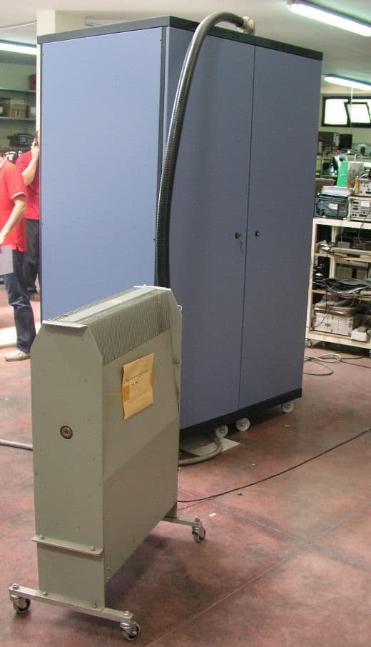
PHLTXUD3000A
Jun 17, 20103000 Watt ATSC Transmitter
Equipment Class
TBC - Licensed Broadcast Station Transmitter
PHLTXUD2000A
Jun 09, 20102000 Watt ATSC Transmitter
Equipment Class
TBC - Licensed Broadcast Station Transmitter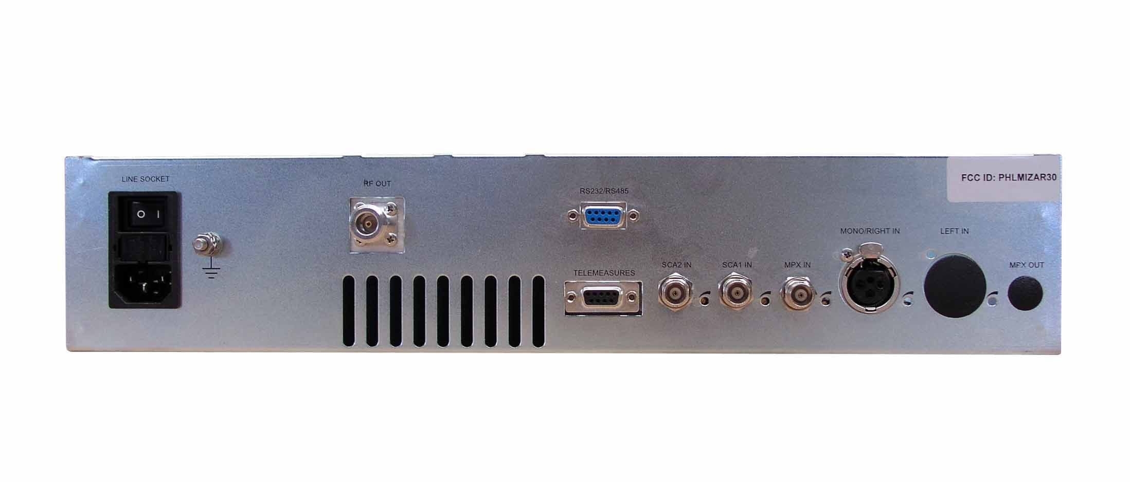
PHLMIZAR30
Jul 01, 200830 Watt FM Broadcast Transmitter
Equipment Class
TBC - Licensed Broadcast Station Transmitter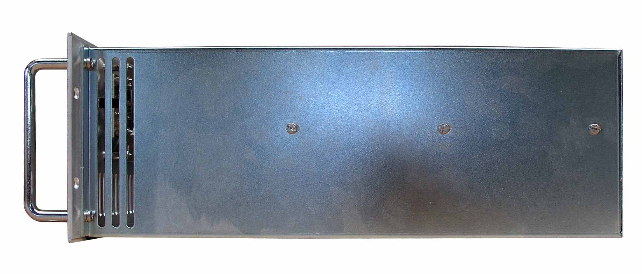
PHLMIZAR300
Jul 01, 2008300 Watt FM Broadcast Transmitter
Equipment Class
TBC - Licensed Broadcast Station Transmitter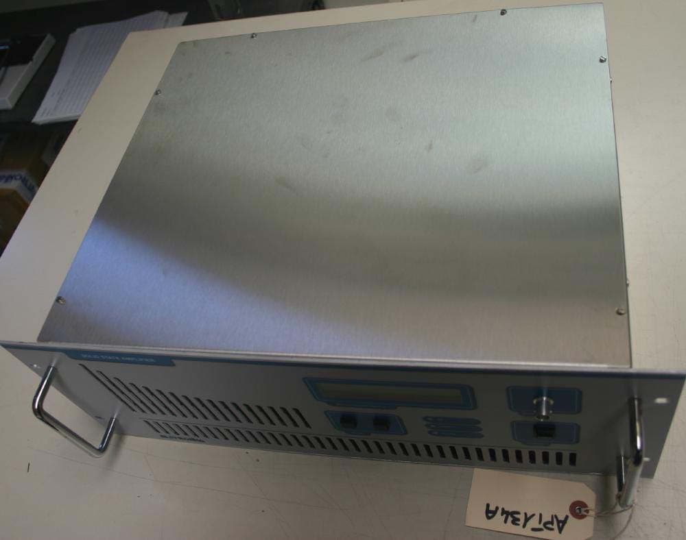
PHLTXUP200
May 29, 2007250 Watt Analog TV Broadcast Transmitter
Equipment Class
TBC - Licensed Broadcast Station Transmitter