PHU-PA-PKSelf-Contained Door Lock
International Electronics Inc.
Click to zoom
Application Details
- Equipment Class
- DCD - Part 15 Low Power Transmitter Below 1705 kHz
- Date of Grant
- May 06, 2001
- Application Purpose
- Original Equipment
- Date of Application
- May 06, 2001
- Equipment Note
- Self-Contained Door Lock
- Frequency Range
- 0.12500000 - 0.12500000
- Country
- United States
Documents & Files
Document Text
Text extracted from the exhibit documents filed with the FCC. Open a document above to read the original.
Users Manual
Installation Instructions For Low Profile Mortise Lock A7454A Table of Contents Warning .......................................................1 General Description .........................................2 Specifications ................................................2 Parts Breakdown ............................................3-5 Features .......................................................5 Installation Instructions...................................6-13 Operational Check ..........................................14 Basic Programming Instructions .........................14 Keypad Only (100 Users–LK) . . . . . . . . . . . . . . . . . . . . . . . . . . . . . 15 Keypad or Proximity/Keypad (500 Users–LU or PK). . . . . . . . . . . . . . . 18 Proximity Only (500 Users–PA) . . . . . . . . . . . . . . . . . . . . . . . . . . . . 22 Chain Programming ........................................23 Transaction Log .............................................24 1 2 3 4 5 6 7 Page 9 8 10 1 This device complies with Part 15 of the FCC Rules. Operation is subject to the following two conditions: (1) this device may not cause harmful interference, and (2) this device must accept any interference received, including interference that may cause undesired operation. Note:This equipment has been tested and found to comply with the limits for a Class B digital device, pursuant to Part 15 of the FCC Rules. These limits are designed to provide reasonable protection against harmful interference in a residential installation. This equipment generates, uses and can radiate radio frequency energy and if not installed and used in accordance with the instructions, may cause harmful interference to radio communications. However, there is no guarantee that the interference will not occur in a particular installation. If this equipment does cause harmful interference to radio or television reception, which can be determined by turning the equipment off and on, the user is encouraged to try to correct the interference by one or more of the following measures: • Reorient or relocate the receiving antenna. • Increase the separation between the equipment and receiver. • Connect the equipment into an outlet on a circuit different from that to which the receiver is connected. • Consult the dealer or an experienced TV technician for help. This Class B digital apparatus complies with Canadian ICES-003 Cet appareil numÈrique de la classe B est conforme ‡ la norme NMB-003 du Canada Warning 1 Warning:Changes or modifications to this unit not expressly approved by the party responsible for compliance could void the user's authority to operate the equipment. 2 • Latchbolt - Stainless Steel • Deadbolt - Stainless Steel • Guardbolt - Stainless Steel, non handed • Handed - Easily field reversible without disassembling the lock body • Case - 12 gauge heavy duty wrought steel • Outside lever controlled by Keypad, Keypad/Prox or Prox only • Inside lever retracts latchbolt and deadbolt • Locks furnished for 1 3/4" doors. Can be furnished for other door sizes upon request. Consult factory • U.L. Listed (3 hr.) 3 Specifications General Description 2 The SARGENT Keypad Mortise Lock/Prox is designed for areas which require authorized entry. It is a self-contained microprocessor-controlled keypad with non volatile solid-state memory. The keypad will hold a total of 100(LK) / 500(LU, PK, PA) different User Codes. User Codes “01”, “02”, and “03” are utilized for Master Code, Emergency Code, and Supervisory Code, respectively. This product is operated by six (6) “AA” Duracell Alkaline Batteries. SARGENT mortise locks are designed with high quality components to provide the high security, performance and durability. Warning ! To comply with “Fire Listed” doors, the batteries must be replaced with Alkaline batteries only. 3 Parts Breakdown 4 11 11 27/28 29 5 4 3 7 2 16 17 15 14 8 9 15 31 21 22 20 20 18/19 25 23 24 26 21 22 26 16 1 17 30 13 13 12 24 ’A’ DESIGN (LH) ’A’ DESIGN (RH) ’B’ DESIGN ’E’ DESIGN ’F’ DESIGN ’H’ DESIGN’J’ DESIGN ’L’ DESIGN ’P’ DESIGN ’W’ DESIGN 33 4 Item #Part#Description# Required 182-3846Outside Escutcheon with Cylinder Hole and Key Pad, or Key Pad / Prox1 82-3847Outside Escutcheon without Cylinder Hole and Key Pad or Key Pad / Prox1 82-3848Outside Escutcheon with Cylinder Hole and Prox Only1 82-3849Outside Escutcheon without Cylinder Hole and Prox Only1 82-0493Outside Escutcheon Housing Only with Cylinder Hole1 82-0495Outside Escutcheon Housing Only without Cylinder Hole1 52-2431 Proximity Circuit Board and Harness Assembly1 52-2432 Key Pad / Proximity Circuit Board and Harness Assembly1 282-3837Inside Escutcheon with Thumb Turn and 100 User Controller1 82-3838Inside Escutcheon without Thumb Turn and 100 User Controller1 82-3839Inside Escutcheon with Thumb Turn and 500 User Controller1 82-3840Inside Escutcheon without Thumb Turn and 500 User Controller1 82-3841Inside Escutcheon with Thumb Turn Prox / Key Pad Controller1 82-3842Inside Escutcheon without Thumb Turn Prox / Key Pad Cont.1 82-0492Inside Escutcheon Housing Only without Thumb Turn1 82-0494Inside Escutcheon Housing Only with Thumb Turn1 52-2440 100 (LK) User Key Pad Controller Assembly1 52-2447 500 (LU, PK) User Key Pad Controller Assembly1 52-2454 Key Pad / Proximity (PK), Proximity Only (PA) Controller Assembly1 352-2437Battery Cover Assembly1 401-1212Security Screw1 501-0297Security Tool1 782-0507Thumb Turn1 877-0772Spindle (Thumb Turn)1 901-0844Washer (Thumb Turn)1 1001-0543Spring Grip Fastener (Thumb Turn)1 1177-0168Thru Bolts #8-32 x 1 7/8” Flat Head Screw2 1252-0033Fire Stop Plate1 1301-1500Fire Stop Screws #8 x 1/2” Type “AB” Phillips Pan Head Self Tap2 1482-3088Inside Spindle Adapter & Plate Assembly1 1501-1495Screw #8-32 x 1/2”2 1682-0368Inside Spindle / Outside Spindle2 1782-0347Inside Spring / Outside Spring2 1882-0081Face Plate no Dead Bolt1 1982-0084Face Plate with Dead Bolt1 2001-1028Face Plate Screws Machine 8-32 x 1/4”2 2101-2299Lock Body Sc…
Text truncated - open the document above for the full version.
Users Manual
13 Installation Instructions (Continued) Step #5 Battery Installation/Application of Front Plate/Optional Gasket •Place (6) AA batteries into the compartment as indicated •Observe polarity when installing “AA” batteries •Install battery keeper clip by inserting tabs into bottom slots first •To remove keeper, pull on top tab •Attach battery cover to inside escutcheon making sure to line up tabs with retaining slots in battery cover •Secure with security screw - + - + - + - + + - + - •Optional gasket (82-0500) intended for exterior applications only Security Screw Security tool 01-0297 included Outside of Door • Front plate (2) Flat head screws •Tighten lockbody screws •Attach front plate and retain with (2) flat head screws 14 The Low Profile Keypad Lock can support 100 (LK) / 500 (LU, PK, PA) users.Each user is assigned a User Number in addition to the code used for entry. Example: USERUSERUSER CODE* TYPENUMBER(2-6 DIGITS) Master011234 Emergency022222 Supervisor03303030 Standard04-97 (LK)265 04-500 (LU, PK, PA)) Programming Instructions for Keypad Operations Only 8 Operational Check 7 •Place key into cylinder and rotate key. •The key will retract the latchbolt. •If the deadbolt is thrown, the key will retract both the deadbolt and the latchbolt. •Inside handle lever retracts latchbolt and deadbolt (if provided). •Enter 1234* to unlock outside lever handle and retract latchbolt and deadbolt (if provided) •If a card or prox is used, present them as shown below •Key should rotate freely. There should be no friction against lock case, wire harness or any other obstructions. •Refer to Step 4 if harness friction exists. •Rotate cylinder further into lock case to eliminate lockbody obstruction. Key/Cylinder, Code Verification Presentation of CardPresentation of FOB Insert into dish 15 Programming Instructions for Keypad Operations Only 8 •Soflink™Plus must be used with (PA) controller for programming •The Master Code is alwaysUser “01”. The Master Code assigns the Emergency and Supervisory Codes. It is also used for programming. Users are deleted through the Master Programming Code only •The Emergency Code is alwaysUser “02”. The Emergency Code will override the deadbolt in the mortise lock and has an unlock time of 10 seconds •The Supervisory Code is alwaysUser “03”. The Supervisory Code allows temporary lockout of selected users, changes duration of unlock time, requests infrared interrogation output, may add additional User Codes and entry when low battery has expired •The first User Code will be User “04” or higher. User numbers do not have to be used or entered sequentially To Begin Programming: The Keypad Mortise Lock is preset at the factory with Master Code “1234”. Entering 1234 * will unlock the lock allowing the lever handle to retract the latchbolt. Initial Set-Up Procedures: •The following are typical procedures to follow when setting up your 8200 Series Keypad • If a mistake is made during any of procedures, depress the “*” several times until the yellow LED goes out • If no keystroke is made in a 30sec time frame the programming up to that point will default and you will have to start over LK Programming To determine which programming steps to use for your lock see the example below: If your label has an LK, then use the programming below. If your label has an LU or PK, turn to the next set of programming. Change Master Code (This Example uses the Factory Default Master) 99# 1234*Yellow LED Blinks 50# 1# 01# New Master Code*Yellow LED Blinks Quickly New Master Code*Yellow LED Blinks Slowly (If Solid, see Note) *Yellow LED Goes Out - + - + - + - + + - + - LK 16 To Enter the Emergency Code (Unlock Duration 10 Seconds) 99# Master Code*Yellow LED Blinks 50# 2# Emergency Code*Yellow LED Blinks Quickly Emergency Code*Yellow LED Blinks Slowly (If Solid, see Note) *Yellow LED Goes Out To Change the Supervisory Code 99# Master Code*Yellow LED Blinks 50# 1# 03# Supervisory Code*Yellow LED Blinks Quickly Supervisory Code*Yellow LED Blinks Slowly (If Solid, see Note) *Yellow LED Goes Out • Factory Default Supervisory Code is 4321 To Enter a User Code 99# Supervisory or master Code*Yellow LED Blinks 50# 1# User number (04-97)# User Code*Yellow LED Blinks Quickly User Code*Yellow LED Blinks Slowly (If Solid, see Note) * Yellow LED Goes Out To Enter a Passage (Maintained) Code When this code is used, it must also be used to re-lock the device. 99# Supervisory or master Code*Yellow LED Blinks 50# 2# User number (04-97)# User Code*Yellow LED Blinks Quickly User Code*Yellow LED Blinks Slowly (If Solid, see Note) * Yellow LED Goes Out To Enter a One Time User Code 99# Supervisory or Master Code*Yellow LED Blinks 50# 5# User number (04-97)# User Code*Yellow LED Blinks Quickly User Code*Yellow LED Blinks Slowly (If Solid, see Note) * Yellow LED Goes Out To Deactivate / Reactivate "Beep" With Key Stroke 99# Supervisory or master Code*Yellow LED Blinks 30# 0# 0# (Off) (1# = On)Yellow LED Blinks *Yellow LED Blinks Quickly * Yellow LED Blinks Slowly (If Solid, see Note) *Yellow LED Goes Out Note: If turning Beep OFF, No audible on last two steps. To Clear the Entire Memory 99# Master Code*Yellow LED Blinks 46# 00000# 00000#Yellow LED Blinks *Yellow LED Blinks Quickly * Yellow LED Goes Solid and Begins to Blink *Yellow LED Goes Out (If Solid, see Note) This Deletes ALL Codes, including Master, Emergency and Supervisory. The Master Code is set back to 1234*, Door Number to 0001 and Unlock Time to 5 Seconds. If the master Code is not known, Factory Assistance will be required to clear the memory. Call 1-800-810-9473 17 For additional information, see “Transaction Log”. To LED location Infrared Printer (52-2069) Door Name 5666 Seq User Trans 0001— 1003— 2003— 3020— 4003— Transaction Number Transaction Type User Number Door Name Note: Seq. # 0 is the programming request to output the entries. Sequence numbers 1-9 are the actual entries. Hold an infrared printer up to the red infrared LED (as shown). An HP82240…
Text truncated - open the document above for the full version.
Block Diagram
1234 A B C D 4321 D C B A Title NumberRevisionSize A Date:1-May-2001 Sheet of File:D:\_PROJE~1\..\PA-PK 2.SCHDrawn By: 432-5066 4041 eProx SH2MR3FSH2PREV4 208-5008 432-5077 432-5088 208-5007 LED_PWR5 MAIN_CD 209-9030 039-5030 PA - PK PRODUCT STRUCTURE KEYPAD - NOT USED ON PA PRODUCT 1 Antenna coil 125Khz signal path Embedded Micro 4 MHz resonator Block diagram of system modules Text Real Time Clock 32.768 KHz
Cover Letter(s)
Federal Communicatio ns Co mmission 7435 Oakland Mills Road Columbia, MD 21046 Gentle me n: This letter is to comply with Section 0.457(d)(2)(i) pertaining to confidential material. International Electronics Inc. would like the following documents regarding this submission for FCC ID: PHU-PA-PK to be kept confidential. 1. Pages 1 of 1 of document SH2mr3f.pdf The above material contains trade secrets or technical data, which would customarily be guarded from competitors. We do not want these documents to be accessible to the general public. Sincerely, C. He ntsc hel VP E ngineering
External Photos
Front View (PA1) Back View (PA1) Front View (PA2) Back View (PA2) Front View (PA3) Back View (PA3) Front View (PK1) Back View (PK1) Front View (PK2) Back View (PK2) Front View (PK3) Back View (PK3)
Internal Photos
The internal composition of the models is the same. The difference between the PA1/2/3 and PK1/2/3 is the PK models have a keypad that is removed on the PA models. Inside rear panel Inside back of rear panel Back rear panel Back rear panel with enclosure separated Back rear panel boards Front of board Close-up of part of the front of the board Close-up of the other part of the front of the board Back of board Close-up of the back of the board Close-up of the other portion of the back of the board Front of small board Back of small board Back of front panel Back of front panel with metal removed Back of front panel with enclosure separated Back of top button board Front of top button board Antenna portion of bottom board Front of antenna board Showing how both sections of the board go together Back door latch Back door latch with ring separated Door latch assembly with rings Door latch assembly without rings Motor assembly Close-up of motor assembly
Internal Photos
The internal composition of the models is the same. The difference between the PA1/2/3 and PK1/2/3 is the PK models have a keypad that is removed on the PA models. Inside rear panel Inside back of rear panel Back rear panel Back rear panel with enclosure separated Back rear panel boards Front of board Close-up of part of the front of the board Close-up of the other part of the front of the board Back of board Close-up of the back of the board Close-up of the other portion of the back of the board Front of small board Back of small board Back of front panel Back of front panel with metal removed Back of front panel with enclosure separated Back of top button board Front of top button board Antenna portion of bottom board Front of antenna board Showing how both sections of the board go together Back door latch Back door latch with ring separated Door latch assembly with rings Door latch assembly without rings Motor assembly Close-up of motor assembly
Operational Description
____________________________________________________________________________________________ HID Corporation 9292 Jeronimo Road Irvine, CA 92618 USA TEL (949) 598-1600 (800) 237-7769 FAX (949) 598-1690 Web page, E-mail - www.prox.com – EProxL End Item Specification 4041A Rev A 1 of 9 End Item Specification – 4041A Rev A EProx Lock Module (eProxL) ____________________________________________________________________________________________ HID Corporation 9292 Jeronimo Road Irvine, CA 92618 USA TEL (949) 598-1600 (800) 237-7769 FAX (949) 598-1690 Web page, E-mail - www.prox.com – EProxL End Item Specification 4041A Rev A 2 of 9 Table Of Contents 1. eProx Lock Module - Product Description.....................................................................3 1.1 Scope..........................................................................................................................3 1.2 Functional Summary....................................................................................................3 1.3 Reference Documents.................................................................................................3 2. Physical Characteristics..................................................................................................3 2.1 Product Identification...................................................................................................3 2.2 eProxL Dimensions......................................................................................................4 2.2.1 Final Assembly......................................................................................................4 2.3 Product Packaging.......................................................................................................4 2.3.1 Packaging Notes...................................................................................................4 2.4 eProxL Reader Connections........................................................................................5 2.5 Product Configuration/Ordering Options......................................................................5 3. Product Specifications....................................................................................................6 3.1 Environmental Characteristics.....................................................................................6 3.2 Power Requirements...................................................................................................6 3.3 Operating Parameters..................................................................................................6 3.4 Accuracy......................................................................................................................6 4. eProxL Reader Functional Description...........................................................................6 4.1 Configuration Option chart...........................................................................................6 4.2 Wiegand Output...........................................................................................................6 4.2.1 Data Pulses - Wiegand..........................................................................................7 4.3 Clock and Data Output.................................................................................................7 4.3.1 Data Pulse – Clock and Data.................................................................................7 4.3.2 Clock & Data Output – message content..............................................................8 4.4 F2F Output..................................................................................................................9 4.4.1 Data Pulse - F2F...................................................................................................9 4.4.2 F2F Output – message content.............................................................................9 ____________________________________________________________________________________________ HID Corporation 9292 Jeronimo Road Irvine, CA 92618 USA TEL (949) 598-1600 (800) 237-7769 FAX (949) 598-1690 Web page, E-mail - www.prox.com – EProxL End Item Specification 4041A Rev A 3 of 9 1. eProxL - Product Description 1.1 Scope This document describes the physical characteristics, functional requirements and software features contained in the eProxL. The eProxL was developed for the single door proximity reader system market. This document also contains the product specifications, which include performance, environmental, regulatory, and operational criteria. 1.2 Functional Summary The eProxL reader is a low power RFID reader intended for use as an access-control component in battery-powered stand-alone electronic door lock systems. When installed into a door lock system, the user need only present an HID proximity card to the vicinity of the eProxL reader antenna in order to open the locked door. The eProxL reader normally operates in a low-power sleep mode until a transponder (ProxCard) is brought near. The reader then activates for a brief time and reads the data from the transponder. The ID data is sent as a serial bit stream to the OEM’s lock controlling board. The OEM board can then compare the card data to a database of ID’s which are authorized to open the door lock. 1.3 Reference Documents The following Standards have been achieved or applied for on previous HID RFID Readers and are for reference only: > Security Industries Association 26-Bit Reader Interface Standard > "UL 294 Underwriters Laboratories Recognized Component 2. Physical Characteristics 2.1 Product Identification The HID model number is 4041A - for the eProxL. ____________________________________________________________________________________________ HID Corporation 9292 Jeronimo Road Irvine, CA 92618 USA TEL (949) 598-1600 (800) 237-7769 FAX (949) 598-1690 Web page, E-mail - www.prox.com – EProxL End Item Specification 4041A Rev A 4 of 9 2.…
Text truncated - open the document above for the full version.
Operational Description
HID Proprietary 1 eProx Design Specification For evaluation by prospective licenseesFor evaluation by prospective licensees This document is made available to prospective licensees of HID eProx technology under the terms of the HID Non Disclosure agreement. The information it contains may be used for no other purpose than the evaluation of the technology with a view to entering into a licensing agreement with HID. The information contained in this document is preliminary and subject to revision. Rev 06 June 7, 1999 HID Proprietary 2 Table of Contents 1. Overview...................................................................................................................................................................................4 2. Passive Radio Frequency Identification Device Overview................................................................................................5 2.1 Reader...............................................................................................................................................................................5 2.2 Tag.....................................................................................................................................................................................5 2.3 Carrier...............................................................................................................................................................................5 2.3.1 Modulation...............................................................................................................................................................5 2.3.2 System Handshake...................................................................................................................................................5 2.3.3 Backscatter Modulation...........................................................................................................................................6 2.3.4 Data Encoding..........................................................................................................................................................6 2.3.5 Data Modulation......................................................................................................................................................6 2.4 Antenna Design Notes......................................................................................................................................................7 2.4.1 Example Antenna Configuration and Design Hints...............................................................................................8 3. eProx Y - Specifications for full Integration....................................................................................................................9 3.1 eProx Y Hardware............................................................................................................................................................9 3.1.1 Description...............................................................................................................................................................9 3.1.2 Functional Block Diagram......................................................................................................................................9 4. eProx D - Proximity technology on a daughter board..................................................................................................10 4.1 General technical information.......................................................................................................................................10 4.1.1 eProx Reader Functionality...................................................................................................................................10 4.1.2 Operating Cycle.....................................................................................................................................................11 4.1.3 Accuracy................................................................................................................................................................11 4.2 eProx D Hardware Section............................................................................................................................................11 4.2.1 Description.............................................................................................................................................................11 4.2.2 Functional Block Diagram....................................................................................................................................12 4.3 eProx D Physical Characteristics..................................................................................................................................12 4.3.1 Circuit Board..........................................................................................................................................................12 4.3.2 Dimensions.............................................................................................................................................................12 4.3.3 Mounting................................................................................................................................................................12 4.3.4 Connectors.............................................................................................................................................................13 4.3.5 Antenna..................................................................................................................................................................13 4.3.6 Product Shipping Preparation................................................................................................................................13 4.4 eProx D Reader Specifications...........................................…
Text truncated - open the document above for the full version.
Schematics
1234 A B C D 4321 D C B A Title NumberRevisionSize A Date:2-Jan-2001 Sheet of File:D:\_PROJE~1\..\EPROX_CC.SCHDrawn By: 2" 28AWG (7/36) Alpha 3048WH005 or equiv. MOLEX 51021-0900 Housing 1 2 J1 CON2 ePA1 & ePC2 eProx to SH2 cables C ePC1 - eProx module to SH2 main PCB ePA2 - eProx module antenna to SH2 amin PCB 2" 28AWG (7/36) Alpha 3048WH005 or equiv. MOLEX 50079 CRIMP MOLEX 51021-0900 Housing MOLEX 50079 CRIMP SH2eProx AMP 173977-2 IDC CONNECTORAMP 173977-2 IDC CONNECTOR IEI # 432-5077 IEI # 432-5088 1 2 3 J5 CON3 N/C 1/2/01 P2 PIN OUT CHANGED TO MATCH HOUSING ORIENTATION 1 2 3 4 5 6 7 8 9 J2 CON9 1 2 3 4 5 6 7 8 9 J2 CON9
Schematics
1234 A B C D 4321 D C B A Title NumberRevisionSize A Date:4-Jan-2001 Sheet of File:D:\_PROJE~1\..\LED_PWR5.SCHDrawn By: ANTENNA ANTENNA LUG 1 PAD3 PCB PAD1 LUG 1 PAD4 PCB PAD1 E Sargent Hub II LED and Power pcb POWER PROBE + POWER PROBE - LED BOARD 1 2 P3 RAIL 2 ANTENNA ANTENNA LUG 1 PAD1 PCB PAD1 LUG 1 PAD2 PCB PAD1 - 1 + 2 SND1 SOUNDER R1 R220-0603 R2 R220-0603 SOLDER PADS MIN. .150" DIA LED1 LED-GREEN-HLMP LED2 LED-RED-HLMP LOCATE LED 1 & 2 SIDE BY SIDE TO APPEAR AS A BICOLOR DEVICE LED4 LED-IR-HSDL 208-5008 PCB NUMBER 205-5008 EGND IR LED + IR LED - YEL LED - YEL LED + GRN LED - GRN LED + ROW 1 ROW 2 ROW 3 ROW 4 COL 1 COL 2 COL 3 EXT PWR - SOUNDER + SOUNDER - NO CONN POLARITY PLUG SHLD ANT1 ANT2 SHLD 1 2 3 4 5 6 7 8 9 10 11 12 13 14 15 16 17 18 19 20 21 22 23 24 P1 MOLEX 10-88-1241 LUG 1 PADA PCB PAD1 MOUNTING HOLES EXT PWR + P1-1 CONNECTOR SIDE OF PCB 12/8/00 (D) Connector reversed to remove twist in cable 12/4/00 (C) Location of aux power point changed A BC D LUG 1 PADB PCB PAD1 LUG 1 PADC PCB PAD1 LUG 1 PADD PCB PAD1 R3 10M 2010 1/4/01 REVISION B PRINT UPDATE TO SHOW 24 PIN HEADER
Schematics
1234 A B C D 4321 D C B A Title NumberRevisionSize A Date:2-Jan-2001 Sheet of File:D:\_PROJE~1\..\MAIN_CD.SCHDrawn By: IEI # 432-5066 SH2 control to keypad cable D INSERT POLARIZING PIN 15-04-0292 AT PIN 19 INSERT POLARIZING PIN 15-04-0292 AT PIN 19 INSERT POLARIZING PIN 15-04-0292 AT PIN 19 MOLEX 8863 .050" PITCH FLAT CABLE PASS THROUGH CONNECTOR 1.5"10" 11.5" EGND IR LED + IR LED - YEL LED - YEL LED + GRN LED - GRN LED + ROW 1 ROW 2 ROW 3 ROW 4 COL 1 COL 2 COL 3 EXT PWR + EXT PWR - SOUNDER + SOUNDER - NO CONN POLARITY PLUG SHLD ANT1 ANT2 SHLD SHK1 12/11/00 CABLE LENGTH CHANGED LED BOARD KEYPAD TO CONTROL UNITCABLE ATTACHMENT TO PCB'S 1 2 3 4 5 6 7 8 9 10 11 12 13 14 15 16 17 18 19 20 21 22 23 24 J1 MOLEX 15-47-3245 1 2 3 4 5 6 7 8 9 10 11 12 13 14 15 16 17 18 19 20 21 22 23 24 JL1 MOLEX 15-47-3245 1 2 3 4 5 6 7 8 9 10 11 12 13 14 15 16 17 18 19 20 21 22 23 24 JK1 MOLEX 15-47-3245 1/2/01 CABLE LENGTH ADJUSTED BETWEEN JL1 AND JK1
Schematics
1234 A B C D 4321 D C B A Title NumberRevisionSize A Date:8-Dec-2000 Sheet of File:D:\_PROJE~1\..\SH2PREV4.SCHDrawn By: SW4 SW-PB SW5 SW-PB SW6 SW-PB SW7 SW-PB SW8 SW-PB SW9 SW-PB SW10 SW-PB SW11 SW-PB…
Text truncated - open the document above for the full version.
Contact Information
Applicant
Christopher Hentschel(VP Engineering)
Technical Contact
CKC Laboratories, Inc.Tracy Phillips
[email protected]1-800-500-4362
5473A Clouds Rest · Mariposa, California · United States
Non-Technical Contact
CKC Laboratories, Inc.Joyce Walker
[email protected]1-800-500-4362
Test Firm
CKC Laboratories, Inc.Steve Behm
Technical Specifications
| # | Rule Parts | Frequency Range | Power Output |
|---|---|---|---|
| 1 | 15C | 0.125 MHz - 0.125 MHz | - |
Other Applications from International Electronics Inc.
PHUES
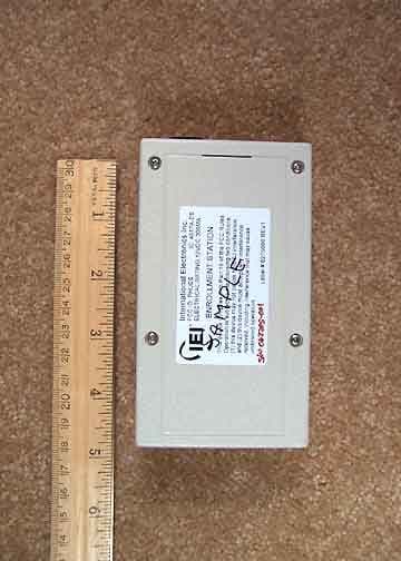
Jul 13, 2005ES Enrollment Station
Equipment Class
DCD - Part 15 Low Power Transmitter Below 1705 kHz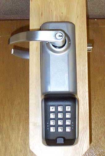
PHULS2P
Feb 10, 2003Self Contained Door Lock, LS2P
Equipment Class
DXX - Part 15 Low Power Communication Device Transmitter