PHULS2PSelf Contained Door Lock, LS2P
International Electronics Inc.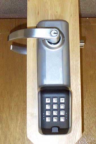
Click to zoom
Application Details
- Equipment Class
- DXX - Part 15 Low Power Communication Device Transmitter
- Date of Grant
- Feb 10, 2003
- Application Purpose
- Original Equipment
- Date of Application
- Feb 10, 2003
- Equipment Note
- Self Contained Door Lock, LS2P
- Frequency Range
- 0.12500000 - 0.12500000
- Country
- United States
Documents & Files
Document Text
Text extracted from the exhibit documents filed with the FCC. Open a document above to read the original.
Users Manual
IEI DoorGard LS2/LS2P Programming Manual www.ieib.comPart Number 6041000 Copyright 2003Rev. 1.0 International Electronics, Inc.Date: 02-03 D3 For more information, contact: International Electronics, Inc.© Copyright 2003 427 Turnpike StreetInternational Electronics, Inc. Canton, MA 02021 U.S.A.All Rights Reserved Published in U.S.A. Telephone: 781-821-5566 800- 733-9502 (sales in MA) 800-343-9502 (sales) Fax:781-821-4443 Fax Information Center:781-821-0734 Internet: www.ieib.com D3 Table of Contents Foreword F.1 About this Manual............................................... vii F.2 Safety Warnings and Cautions ......................... vii F.3 FCC Statement ..................................................... vii F.4 Design Change Disclaimer................................. viii F.5 Reproduction Disclaimer.................................... viii F.6 Technical Support................................................ viii F.7 Warranty ............................................................... ix DoorGard LS2/LS2P System Programming Guide 1.1 Features ................................................................. 1-1 1.1.1 Specifications.................................................. 1-2 1.1.2 Battery Powered............................................ 1-2 1.1.2.A Low Voltage Operation ...................... 1-2 1.1.2.B Low Voltage Warning ......................... 1-3 1.1.2.C Inhibit Operation Warning ................ 1-3 1.1.2.D Lock Prior to Sleep .............................. 1-3 1.2 Programming the Keypad.................................. 1-4 1.2.1 Master Code ................................................... 1-4 1.2.2 User #2, Supervisor...................................... 1-5 1.3 Programming Keypad Options and Parameters................................................................... 1-6 1.3.1 Set Lock Time...........................................1-6 1.3.2 Propped and Forced Door Audio Alerts... 1-6 1.3.2.A Forced Door Audio Alert .................... 1-7 1.3.3 Propped Door Audio Alert.......................... 1-7 DoorGard LS2/LS2P System Programming Manual, D3iii 1.3.4 Request-To-Exit (REX) Input .......................1-8 1.3.5 User Lockout Option ....................................1-8 1.3.5.A Lockout By Location ............................1-8 1.3.5.B Lockout By Group ................................1-9 1.3.6 Error Lockout Option ...................................1-10 1.3.7 Turning Audio Keypress Feedback ON/OFF ....................................................................1-10 1.3.8 Turning Visual LED/Keypress Indicator ON/OFF ....................................................................1-11 1.3.9 Auto Entry.......................................................1-12 1.3.10 TimeZone/Holiday Features ......................1-12 1.3.10.A Midnight Crossing TimeZones.........1-14 1.3.10.B Holidays ................................................1-14 1.3.10.C Daylight Savings Time .......................1-14 1.3.10.D Leap Year .............................................1-15 1.3.10.E Time/Date Set.......................................1-15 1.3.11 Transaction Event Log ................................1-15 1.3.12 Communications ..........................................1-15 1.3.13 DoorGard LS2/LS2P Default Settings.......1-16 1.3.14 Restoring System Defaults .........................1-19 1.3.15 Erasing User Table/Restore System Defaults .....................................................................1-19 1.4 Programming Users .............................................1-20 1.4.1 User Features ..................................................1-20 1.4.2 User Codes ......................................................1-22 1.4.3 Enabling/Disabling Users Command .........1-23 1.4.4 Adding New or Changing Existing Codes.........................................................................1-23 1.4.4.A Examples ................................................1-24 1.5 Programming Commands ..................................1-26 Appendix A: Users Chart Table of Contents ivDoorGard LS2/LS2P System Programming Manual, D3 List of Tables Table 1-1.Specifications ....................................... 1-2 Table 1-2.DoorGard LS2/LS2P Default Settings .................................................1-16 Table 1-3.DoorGard LS2/LS2P LED Indicators/Sounder Operations........ 1-17 Table 1-4.User Types ...........................................1-21 Table 1-5.Program Commands.......................... 1-26 DoorGard LS2/LS2P System Programming Manual, D3v Foreword F.1 About this Manual This manual is designed for installers of the Interna- tional Electronics DoorGard LS2/LS2P system. All pro- gramming instructions and other relevant information is contained in this manual. This manual describes all the features currently sup- ported in the LS2/LS2P hardware only. It does not cover any of the features or functionality in the PDA or Hubmanager Pro 4.x software. Please refer to those respective manuals for those details. F.2 Safety Warnings and Cautions When handling the main printed circuit board, to guard against possible static discharges, touch a grounded object BEFORE touching the DoorGard LS2/LS2P system. Static shock can render the product unusable. Commands mentioned in the description paragraph are all listed in Table 1-4. F.3 FCC Statement This equipment has been tested and found to comply with the limits for a Class B digital device, pursuant to Part 15 of the FCC Rules. These limits are designed to provide reasonable protection against harmful inter- ference in a residential installation. This equipment generates, uses, and can radiate radio frequency en- ergy and, if not installed and used in accordance with the instructions, may cause harmful interference to radiocommunications. However,thereisnoguaran- tee that interference will not occur in a particular in- stallation. If this equipment does cause harmful inter- ference to radio or television r…
Text truncated - open the document above for the full version.
External Photos
Front Back Left Side Right Side
ID Label/Location Info
LS2 FCC Label location.doc International Electronics Inc. LS2 FCC Label Location Battery cover removed 1/31/03 Locate Label here on the side of the electronics module – shown with battery cover removed
Internal Photos
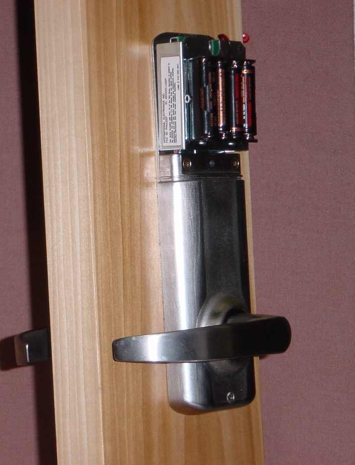
Front Overall View Back Overall View Front Overall View Digital Board - Battery Back Overall View Digital Board - Battery Back of Keypad Back of Keypad with Cover Removed Overall View – Back of Keypad and Large RF PCB Digital Board – Cover Removed Front of Large PCB Close-Up Back of Large PCB Close-Up Front Close-Up Entire Digital Board Close-Up of Partial Digital Board – Front Part 1 Close-Up of Partial Digital Board – Front Part 2 Close-Up of Back of Digital Board Overall View of Small RF PCB Board Close-Up of Small PCB Board - Front Close-Up of Small PCB Board - Back
Test Report
Page 1 of 21 Report No.: FC03-010A ADDENDUM TO FC03-010 FOR THE SELF CONTAINED DOOR LOCK, LS2 & LS2P FCC PART 15 SUBPART C SECTION 15.209 & SUBPART B SECTION 15.109 CLASS B COMPLIANCE DATE OF ISSUE: FEBRUARY 10, 2003 PREPARED FOR: International Electronics, Inc. 427 Turnpike Street Canton, MA 02021 PREPARED BY: Mary Ellen Clayton CKC Laboratories, Inc. 5473A Clouds Rest Mariposa, CA 95338 P.O. No.: 20587 W.O. No.: 80096 Date of test: January 23, 2003 Report No.: FC03-010A This report contains a total of 21 pages and may be reproduced in full only. Partial reproduction may only be done with the written consent of CKC Laboratories, Inc. The results in this report apply only to the items tested, as identified herein. Page 2 of 21 Report No.: FC03-010A TABLE OF CONTENTS Administrative Information .............................................................................................3 Summary of Results .........................................................................................................4 Conditions for Compliance ..............................................................................................4 Approvals .........................................................................................................................4 Equipment Under Test (EUT) Description ......................................................................5 15.31 Voltage Variation...................................................................................................5 15.31 Number Of Channels .............................................................................................5 15.33 Frequency Ranges Tested ......................................................................................5 15.35 Analyzer Bandwidth Settings Per Frequency Range .............................................5 15.203 Antenna Requirements.........................................................................................5 15.205 Restricted Bands ..................................................................................................5 Eut Operating Frequency .................................................................................................5 Temperature And Humidity During Testing....................................................................5 Equipment Under Test .....................................................................................................6 Peripheral Devices ...........................................................................................................6 Report of Measurements ..................................................................................................7 Table 1: 15.209 Fundamental Emission Levels ...................................................7 Table 2: 15.209 Six Highest Radiated Emission Levels......................................8 Table 3: 15.109 Six Highest Radiated Emission Levels......................................9 20 dB Bandwidth Plot ..........................................................................................10 Measurement Uncertainty ................................................................................................11 EUT Setup........................................................................................................................11 Correction Factors............................................................................................................11 Table A: Sample Calculations .............................................................................11 Test Instrumentation and Analyzer Settings ....................................................................12 Spectrum Analyzer Detector Functions ...............................................................12 Peak..........................................................................................................12 Quasi-Peak ...............................................................................................12 Average ....................................................................................................12 EUT Testing.....................................................................................................................13 Radiated Emissions ..............................................................................................13 Appendix A: Test Setup Photographs..............................................................................14 Photograph Showing Radiated Emissions ...........................................................15 Photograph Showing Radiated Emissions ...........................................................16 Appendix B: Test Equipment List ...................................................................................17 Appendix C: Measurement Data Sheets ..........................................................................18 Page 3 of 21 Report No.: FC03-010A ADMINISTRATIVE INFORMATION DATE OF TEST: January 23, 2003 DATE OF RECEIPT: January 23, 2003 PURPOSE OF TEST: To demonstrate the compliance of the Self Contained Door Lock, LS2 & LS2P with the requirements for FCC Part 15 Subpart C Section 15.209 and Subpart B Section 15.109 Class B devices. Addendum A is to revise the test equipment list for radiated emissions. TEST METHOD: ANSI C63.4 (1992) MANUFACTURER: International Electronics, Inc. 427 Turnpike Street Canton, MA 02021 REPRESENTATIVE: Chris Hentschel TEST LOCATION: CKC Laboratories, Inc. 5473A Clouds Rest Mariposa, CA 95338 Page 4 of 21 Report No.: FC03-010A SUMMARY OF RESULTS As received, the International Electronics, Inc. Self Contained Door Lock, LS2 & LS2P was found to be fully compliant with the following standards and specifications: United States ! FCC Part 15 Subpart B Section 15.109 Class B ! FCC Part 15 Subpart C Section 15.209 ! ANSI C63.4 (1992) method Canada RSS-210 using: ! FCC Part 15 Subpart B Section 15.109 Class B ! FCC Part 15 Subpart C Secti…
Text truncated - open the document above for the full version.
Test Setup Photos
PHOTOGRAPH SHOWING RADIATED EMISSIONS Radiated Emissions - Front View PHOTOGRAPH SHOWING RADIATED EMISSIONS Radiated Emissions - Back View
Contact Information
Applicant
Christopher Hentschel(VP Engineering)
Technical Contact
CKC Laboratories, Inc.Mary Ellen Clayton
[email protected]209-966-5240
5473A Clouds Rest · Mariposa, California · United States
Non-Technical Contact
CKC Laboratories, Inc.Mary Ellen Clayton
[email protected]209-966-5240
Test Firm
CKC Laboratories, Inc.Steve Behm
Technical Specifications
| # | Rule Parts | Frequency Range | Power Output |
|---|---|---|---|
| 1 | 15C | 0.125 MHz - 0.125 MHz | - |
Other Applications from International Electronics Inc.
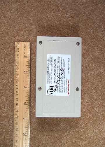
PHUES
Jul 13, 2005ES Enrollment Station
Equipment Class
DCD - Part 15 Low Power Transmitter Below 1705 kHz
PHU-PA-PK
May 06, 2001Self-Contained Door Lock
Equipment Class
DCD - Part 15 Low Power Transmitter Below 1705 kHz