PIZGH940782.4 GHz Analog Cordless Phone
CIDMATE International Technology Inc.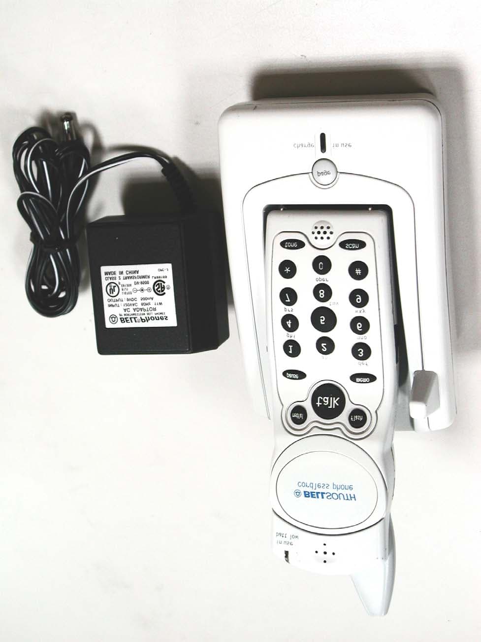
Click to zoom
Application Details
- Equipment Class
- DXX - Part 15 Low Power Communication Device Transmitter
- Date of Grant
- Jul 08, 2002
- Application Purpose
- Original Equipment
- Date of Application
- Jul 08, 2002
- Equipment Note
- 2.4 GHz Analog Cordless Phone
- Frequency Range
- 2474.00000000 - 2475.95000000
- Country
- Taiwan
Documents & Files
Document Text
Text extracted from the exhibit documents filed with the FCC. Open a document above to read the original.
Users Manual
1 Contents Safety Instructions-------------------------------------------------------------------------------------------- 2 Getting Started------------------------------------------------------------------------------------------------ 4 Desk Mounting------------------------------------------------------------------------------------------------- 7 Wall Mounting------------------------------------------------------------------------------------------------- 8 Basic Operation--------------------------------------------------------------------------------------------- 1 0 Receiving Calls---------------------------------------------------------------------------------------------- 11 Placing Calls------------------------------------------------------------------------------------------------- 1 2 Headset Feature--------------------------------------------------------------------------------------------- 1 2 Storing Numbers--------------------------------------------------------------------------------------------- 1 3 Recalling Stored Numbers------------------------------------------------------------------------------- 1 4 Security System--------------------------------------------------------------------------------------------- 1 5 Recharging the Battery Pack---------------------------------------------------------------------------- 1 6 Changing the Battery Pack------------------------------------------------------------------------------ 1 7 Problem Solving-------------------------------------------------------------------------------------------- 1 8 Technical Information------------------------------------------------------------------------------------- 1 9 FCC Requirements------------------------------------------------------------------------------------------ 2 0 Warranty-------------------------------------------------------------------------------------------------------- 2 2 Wall Mounting Template--------------------------------------------------------------------------------- 2 6 2 Safety Instructions IMPORTANT SAFETY INSTRUCTIONS To reduce the risk of fire, electric shock and/or injury, always follow these basic safety precautions when using your cordless telephone equipment. 1. Read and understand all instructions. 2. Follow all warnings and instructions marked on the telephone. 3. Unplug this telephone from the wall outlet before cleaning or replacing the BATTERY PACK. Do not use liquid cleaners or aerosol cleaners. Use a damp cloth for cleaning. 4. Do not use this telephone near water, for example, near a bath tub, wash bowl, kitchen sink, or laundry tub, in a wet basement, or near a swimming pool. 5. Place this telephone on a stable surface. Serious damage and/or injury may result if the telephone falls. 6. Do not cover the slots and openings on this telephone. This telephone should not be placed near or over a radiator or heat register. This telephone should not be placed in a built-in installation unless proper ventilation is provided. 7. Operate this telephone using the electrical voltage as stated on the BASE UNIT of the telephone or the Owner s Manual. If you are not sure of the voltage in your home, consult your dealer or local power company. 8. Do not place anything on the power cord. Install the telephone where no one will step or trip on the cord. 9. Do not overload wall outlets or extension cords as this can increase the risk of fire or electric shock. 10. Never push objects of any kind through slots in the telephone. They could touch dangerous voltage points or short out parts that could result in a risk of fire or electric shock. Never spill liquid of any kind on the telephone. 11. To reduce the risk of electric shock do not disassemble this telephone. Take it to a qualified serviceman when service or repair work is required. Opening or removing covers may expose you to dangerous voltages or other risks. Incorrect reassembly can cause electric shock when the telephone is subsequently used. 12. Unplug this telephone from the wall outlet and consult a qualified service representative in any of the following situations: A. When the power supply cord is frayed or damaged. B. If liquid has been spilled into the telephone. C. If the telephone has been exposed to rain or water. D. If the telephone does not operate normally by following the operating instructions. Adjust only those controls that are covered by the operating instructions. Improper adjustment of other controls may result in damage and will often require extensive work by a qualified technician to restore the telephone to normal operation. 3 E. If the telephone has been dropped or the case has been damaged. F. If the telephone exhibits a distinct change in performance. 13. Do not use the telephone to report a gas leak in the vicinity of the leak. 14. Never install telephone wiring during a lightning storm. 15. Never install telephone jacks in wet locations unless the jack is specifically designed for wet locations. 16. Never touch uninsulated telephone wires or terminals unless the telephone line has been disconnected at the network interface. 17. Use caution when installing or modifying telephone lines. SAVE THESE INSTRUCTIONS Battery Safety CAUTION: Danger of explosion if the BATTERY PACK is incorrectly replaced. Replace only with the same or equivalent type. To reduce the risk of fire or personal injury, read and follow these instructions: 1. Use only the following type and size of BATTERY PACK: Cordless Telephone BATTERY PACK 3.6V, 600mAh U.S. Electronics Inc. Ni-MH BATTERY PACK: Model B655 (See page 16 for ordering information.) 2. Do not dispose of the BATTERY PACK in a fire. It may explode. Check with local codes for possible special disposal instructions. 3. Do not open or mutilate the BATTERY PACK. Released electrolyte is corrosive and may cause damage to the eyes or skin. Electrolyte may be toxic if swallowed. 4. Exercise care in handling the BATTERY PACK to prevent shorting the BATTERY PACK …
Text truncated - open the document above for the full version.
Block Diagram
9407bblk.sch-1 - Fri Feb 08 10:13:46 2002 9407hblk.sch-1 - Fri Feb 08 10:17:06 2002
ID Label/Location Info
LABEL Position: (Base) LABEL Position: (Handset)
Operational Description
CIDMATE International Technology Inc. 3F-B, No. 58, Sec. 1, Minsheng E. Rd., Taipei, Taiwan 104, R.O.C. Tel: 886-2- 2521-8658 Fax: 886-2-2561-6624 Email: [email protected] OPERATION DESCRIPTION HANDSET 1. RF/Audio Section The radio link Handset and Base is full duplex at 2400/2483.5 MHz with the 40 channels. FM modulation is used for the link. The 1 st IF frequency is 10.7MHz and the 2 nd IF frequency is 450KHz. The operating frequency for the cordless phone is selected from one of the following channels and controlled by the synthesizer U2 that is programmed by the MCU. This section is common to both handset and base as the same ICs are used LMX1602(U2), KA3361(U1) is made up of dual serial input PLL frequency synthesizer with 1000MHz prescaler. KA3361 is a narrow-band IF detector IC. 1.1 Receiver The receiver section is made of double conversion with 10.7MHz as the first and second IF. Rx signal from the duplexer circuit is amplified by a Low Noise RF transistor and passed to a Mixer (Q2), and it is converted to 10.7MHz IF and it is then double converted to 450KHz IF in the internet mixer of U1. Voice/data signal is demodulated and output from pin9 of U1. The demodulated signal is then divided into two paths, a path is fed into the data amplifier Q1, Q10. The other path will go through a de-emphasized amplifier and an expander in IC1. Recovered signal can be muted by the pin 13 of IC1,the volume level of the signal can be controlled by the push switch SW1. 1.2 Transmitter Audio signal (from Microphone for headset/Tip & Ring for base) is first fed into the amplifier and compressor inside IC1(IC2 for Base). The signal will pass through a limiter. The AGC and the limiter have the property to limit the maximum signal that feed into the transmitter so that the RF deviation is limited. The transmitter section mainly divided into two parts. They are the voice/data modulator and the Tx power amplifier. The voltage-controlled oscillator VCO operated at the Tx frequency controlled by the synthesizer is modulated by the audio and data signals. Modulated signal is amplified by the RF amplified and sending the signal to the duplexer for radiation by the antenna. 1.3 Band-Pass Filter(BPF) The function of the Two Band-Pass Filter(BPF) is to individual fed the transmitting and receiving signals to a common antenna while providing isolation and rejection of CIDMATE International Technology Inc. 3F-B, No. 58, Sec. 1, Minsheng E. Rd., Taipei, Taiwan 104, R.O.C. Tel: 886-2- 2521-8658 Fax: 886-2-2561-6624 Email: [email protected] interference and other spurious signals. 1.4 Alerter The alerting signals include the following: Ringing, Paging, Key beep and Low battery warning tone. These tones are generated by the MCU to the alerter through the driving circuit formed Q5,Q6 and the associated components. 1.5 Headset microphone The condenser microphone is in the headset and it biased by the resistor R6. The signal is applied to the amplifier inside IC1 2. MCU 2.1 Battery Detect The voltage detector is composed of U3 that is used to detect battery low condition. The detecting accuracy of the voltage detector is +/- 0.2V. The detect pin BAT-LOW is connected to the pin 70 of MCU. 2.2 Carrier Detection This 40 channels cordless has the features of auto-scanning. This is done by the detection of the RSSI at pin 72 of MCU of handset. During PHONE on or CHANNEL changing, the MCU will select the clearest channel for the RF communication. BASE 3. RF/Audio sections The operation of the RF/Audio section is similar to that of the handset. 4. Telephone Network 4.1 Telephone interface Fuse FUSEx is for over-voltage protection. Relay RL1 controls the on/off hook state and pulse dialing. The Tip& Ring are isolated from the base circuit by the transformer T1, relay RL1. CIDMATE International Technology Inc. 3F-B, No. 58, Sec. 1, Minsheng E. Rd., Taipei, Taiwan 104, R.O.C. Tel: 886-2- 2521-8658 Fax: 886-2-2561-6624 Email: [email protected] 4.2 Ring Detect When ring signal is present on the Tip Ring, and envelope waveform of the ring pattern will transfer to pin 20 of MCU by the LM324 pin 14. The MCU will read this waveform and determine whether it will send ringer command. 4.3 Sidtone Cancellation Network The sidetone cancellation is a hybrid circuit of the Tx and Rx paths of the telephone circuit formed by the Q12. 5. MCU 5.1 Charging Network Base charging circuit provides a DC current for handset battery. Resistor R129 controls the current flow. 5.2 Carrier Detection This is similar to the handset counterpart. 6. Digital Answer System Digital Answer System is consist of a DSP chip (MX93132, U7) and flash memory chip (MX29F400T, U4), audio output amplifier for audio (LM386, U10) 6.1 MX93132 provides speech processing/ management modules, including speech compression/ decompression silence management, telephone line signal processing RAM Management line echo cancellation and acoustical echo cancellation, etc. 6.2 MX29F400T: Memory Chip - resources of DAS. 6.3 LM386: Amplifier for audio output.
Schematics
9407b1a0.sch-1 - Fri Feb 08 10:10:56 2002 9407h1k1.sch-1 - Fri Feb 08 10:15:24 2002
Test Report
Test Report ------------------------------------------------------------------------------ 1/36 Report No.: C5015424, 2.4GHz Analog Cordless Phone, FCC Part 15 Class B Training Research Co., Ltd. TEL:886-2-26935155, Fax:886-2-26934440 MEASUREMENT REPORT of CORDLESS TELEPHONE Applicant : CIDMATE International Technology Inc. Model No. : GH9407xx, GH9408xx (x could be blank, numbers or alphabets) EUT : 2.4GHz Analog Cordless Phone FCC ID : PIZGH94078 Report No. : C5015424 Test by : Training Research Co., Ltd. TEL : 886-2-26935155 FAX : 886-2-26934440 2, Lane 194, Huan-Ho Street, Hsichih, Taipei Hsien 221, Taiwan, R.O.C. Test Report ------------------------------------------------------------------------------ 2/36 Report No.: C5015424, 2.4GHz Analog Cordless Phone, FCC Part 15 Class B Training Research Co., Ltd. TEL:886-2-26935155, Fax:886-2-26934440 CERTIFICATION We here by verify that: The test data, data evaluation, test procedures and equipment configurations shown in this report were made mainly in accordance with the procedures given in ANSI C63.4 (1992) as a reference. All test were conducted by Training Research Co., Ltd., 2, Lane 194, Huan-Ho Street, Hsichi, Taipei Hsien 221, Taiwan, R.O.C. Also, we attest to the accuracy of each. We further submit that the energy emitted by the sample EUT tested as described in the report is in compliance with the technical requirements set forth in the FCC Rules Part 15 Subpart C Section 15.249. Applicant : CIDMATE International Technology Inc. Product Name : 2.4Hz Analog Cordless Phone Model No. : GH9407xx, GH9408xx (x could be blank, numbers or alphabets) FCC ID : PIZGH94078 Report No. : C5015424 Test Date : June 6, 2002 Prepared by: Approved by: JACK TSAI FRANK TSAI Test by : Training Research Co., Ltd. TEL : 886-2-26935155 FAX : 886-2-26934440 2, Lane 194, Huan-Ho Street, Hsichih, Taipei Hsien 221, Taiwan, R.O.C. Test Report ------------------------------------------------------------------------------ 3/36 Report No.: C5015424, 2.4GHz Analog Cordless Phone, FCC Part 15 Class B Training Research Co., Ltd. TEL:886-2-26935155, Fax:886-2-26934440 Tables of Contents I. GENERAL 1.1 Introduction ................................................................................................................ 6 1.2 Description of EUT .................................................................................................... 6 1.3 Description of Support Equipment ............................................................................. 6 1.4 Configuration of System Under Test ......................................................................... 7 1.5 Test Procedure ............................................................................................................ 7 1.6 Location of the Test Site ............................................................................................ 8 1.7 General Test Condition .............................................................................................. 8 II. Conducted Emissions Measurements 2.1 Test Condition & Setup ............................................................................................. 9 2.2 List of Test Instruments ............................................................................................. 9 2.3 Test Result of Conducted Emissions ........................................................................ 10 III. Radiated Emissions Measurements 3.1 Test Condition & Setup ............................................................................................ 14 3.2 List of Test Instruments ............................................................................................ 15 3.3 Test Result of Radiated Emissions ........................................................................... 16 3.4 Test Result of Spurious Radiated Emissions ............................................................ 17 IV. Verify Frequencies and Channels ............................................................................. 29 Appendix A ........................................................................................................................ 30 Appendix B ......................................................................................................................... 31 Appendix C ........................................................................................................................ 36 Test Report ------------------------------------------------------------------------------ 4/36 Report No.: C5015424, 2.4GHz Analog Cordless Phone, FCC Part 15 Class B Training Research Co., Ltd. TEL:886-2-26935155, Fax:886-2-26934440 TABLES Table 1 Power Line Conducted Emissions [Channel 01].............................................. 10 Table 2 Power Line Conducted Emissions [Channel 21].............................................. 11 Table 3 Power Line Conducted Emissions [Channel 40].............................................. 12 Table 4 Power Line Conducted Emissions [Charging Mode]....................................... 13 Table 5 Open Field Fundamental Emissions ............................................................... 16 Table 6 Open Field Radiated Emissions [Base Channel 01 Horizontal 30MHz to1GHz] ............................................... 17 Table 7 Open Field Radiated Emissions [Base Channel 01 Vertical 30MHz to 1GHz] ............................................... 17 Table 8 Open Field Radiated Emissions [Base Channel 01 Horizontal 1GHz to 25GHz] ............................................. 18 Table 9 Open Field Radiated Emissions [Base Channel 01 Vertical 1GHz to 25GHz] ................................................. 18 Table 10 Open Field Radiated Emissions [Base Channel 21 Horizontal 30MHz to 1GHz] ............................................ 19 Table 11 Open Field Radiated Emissions [Base Channel 21 Vertical 30MHz to 1GHz] .................................................. 19 T…
Text truncated - open the document above for the full version.
Test Setup Photos
Test Setup Photos ------------------------------------------------------------------------- 1/5 FCC ID: PIZGH94078 Training Research Co., Ltd., TEL: 886-2-26935155, Fax: 886-2-26934440 Conducted Emissions Test Configuration (Idle, Charging mode) Test Setup Photos ------------------------------------------------------------------------- 2/5 FCC ID: PIZGH94078 Training Research Co., Ltd., TEL: 886-2-26935155, Fax: 886-2-26934440 Conducted Emissions Test Configuration (Operating mode) Test Setup Photos ------------------------------------------------------------------------- 3/5 FCC ID: PIZGH94078 Training Research Co., Ltd., TEL: 886-2-26935155, Fax: 886-2-26934440 Radiated Test Setup Placement: (Front/Rear View, BASE) Test Setup Photos ------------------------------------------------------------------------- 4/5 FCC ID: PIZGH94078 Training Research Co., Ltd., TEL: 886-2-26935155, Fax: 886-2-26934440 Radiated Test Setup Placement: (Front/Rear View, HANDSET) Test Setup Photos ------------------------------------------------------------------------- 5/5 FCC ID: PIZGH94078 Training Research Co., Ltd., TEL: 886-2-26935155, Fax: 886-2-26934440 Radiated Test Setup Placement: (Front/Rear View, Charging) The test configuration for frequency between 1 GHz to 25 GHz is same as above.
Contact Information
Applicant
Beryl Liu(Sales Asst. Manager)
Test Firm
Training Research Co., Ltd.Jack Tsai
Technical Specifications
| # | Rule Parts | Frequency Range | Power Output |
|---|---|---|---|
| 2 | 15C | 2.47 GHz - 2.48 GHz | - |
Other Applications from CIDMATE International Technology Inc.
PIZGH9492
Mar 28, 20042.4 GHz Analog Cordless Phone with CID and DAM
Equipment Class
DXX - Part 15 Low Power Communication Device Transmitter
PIZGH9764
Mar 24, 20042.4GHz DSST Multi-Handset w/ CID+DAM
Equipment Class
DTS - Digital Transmission System
PIZXG34001
Aug 17, 20032.4GHz ANALOG CORDLESS PHONE
Equipment Class
DXX - Part 15 Low Power Communication Device Transmitter
PIZMINI1
Jul 24, 20032.4 GHz Analog Cordless Telephone with CID
Equipment Class
DXX - Part 15 Low Power Communication Device Transmitter
PIZXG32010
Jul 09, 20032.4GHz ANALOG CORDLESS PHONE
Equipment Class
DXX - Part 15 Low Power Communication Device Transmitter