PIZMH9910900 MHz Cordless Phone
CIDMATE International Technology Inc.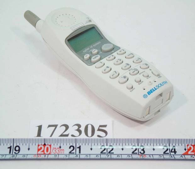
Click to zoom
Application Details
- Equipment Class
- DXX - Part 15 Low Power Communication Device Transmitter
- Date of Grant
- Jan 08, 2002
- Application Purpose
- Original Equipment
- Date of Application
- Jan 08, 2002
- Equipment Note
- 900 MHz Cordless Phone
- Frequency Range
- 925.37500000 - 927.32500000
- Country
- Taiwan
Documents & Files
Document Text
Text extracted from the exhibit documents filed with the FCC. Open a document above to read the original.
Users Manual
1 Contents Safety Instructions --------------------------------------------------------------------------------------------3 HANDSET Controls - Location and Function---------------------------------------------------------5 BASE UNIT Controls - Location and Function -------------------------------------------------------7 Getting Started------------------------------------------------------------------------------------------------9 Desk Mounting -----------------------------------------------------------------------------------------------12 Wall Mounting-----------------------------------------------------------------------------------------------13 Cordless Telephone Operation-------------------------------------------------------------------------14 Preparing for Use----------------------------------------------------------------------------------------14 Receiving Calls------------------------------------------------------------------------------------------15 Extension Phones---------------------------------------------------------------------------------------15 Placing Calls---------------------------------------------------------------------------------------------16 Using the Headset Feature---------------------------------------------------------------------------16 HANDSET Redial Feature----------------------------------------------------------------------------17 Caller ID System Operation------------------------------------------------------------------------------18 Caller ID System-----------------------------------------------------------------------------------------18 Viewing Caller Information During Incoming Calls--------------------------------------18 Message Waiting-----------------------------------------------------------------------------------19 Call Waiting------------------------------------------------------------------------------------------19 Caller List--------------------------------------------------------------------------------------------------19 Viewing the Caller List----------------------------------------------------------------------------19 Placing a Call From the Caller List-----------------------------------------------------------20 Editing the Caller List Before Dialing--------------------------------------------------------20 Saving the Name and Number in the Caller List into the DIRECTORY----------20 Deleting All Records in the Caller List-------------------------------------------------------21 Selective Deleting in the Caller List---------------------------------------------------------21 Name and Telephone Number DIRECTORY --------------------------------------------------21 Viewing the DIRECTORY------------------------------------------------------------------------21 Speed Viewing the DIRECTORY--------------------------------------------------------------21 2 Contents Saving in the DIRECTORY----------------------------------------------------------------------22 Preferred Calls---------------------------------------------------------------------------------------22 Blacked Calls-----------------------------------------------------------------------------------------22 Editing Name and Number in the DIRECTORY------------------------------------------23 Editing the Number in the DIRECTORY before Dialing-------------------------------24 Placing Calls from the DIRECTORY ---------------------------------------------------------25 Deleting All Records in the DIRECTORY---------------------------------------------------25 Selective Deleting in the DIRECTORY-----------------------------------------------------25 Function Operation-------------------------------------------------------------------------------------26 A. Language-----------------------------------------------------------------------------------------27 B. Silent On/Off-------------------------------------------------------------------------------------27 C. Time Set------------------------------------------------------------------------------------------27 D. Ringer Volume-----------------------------------------------------------------------------------28 E. LCD Contrast -------------------------------------------------------------------------------------28 F. PBX Number--------------------------------------------------------------------------------------28 G. PBX Mode----------------------------------------------------------------------------------------29 H. Pause Time --------------------------------------------------------------------------------------29 I. MSG Waiting (Message Waiting) -----------------------------------------------------------29 Telephone Keypad Characters---------------------------------------------------------------------30 Security---------------------------------------------------------------------------------------------------------31 Recharging the Battery Pack----------------------------------------------------------------------------32 Changing the Battery Pack ------------------------------------------------------------------------------33 Problem Solving--------------------------------------------------------------------------------------------34 Technical Information-------------------------------------------------------------------------------------36 FCC Requirements------------------------------------------------------------------------------------------37 Warranty--------------------------------------------------------------------------------------------------------39 Wall Mount Template-------------------------------------------------------------------------------------43 3 Safety Instructions IMPORTANT SAFETY INSTRUCTIONS To reduce the risk of fire, electric shock and/or injury, always follow these basic safety precautions when using your cordless telephone equipment. 1. Read and understand all instructions. 2. Follow all warnings and instructions marked on the telephone. 3. Unplug this telephone from the wall outlet before cleaning or…
Text truncated - open the document above for the full version.
Block Diagram
BASEBD.SCH-1 - Mon Dec 31 15:20:48 2001 HANSETBD.SCH-1 - Mon Dec 31 15:19:02 2001
External Photos
FC C ID : PIZM H 9910 FRONT SIDE OF EUT N u mber 1 172305- 01.J P G FC C ID : PIZM H 9910 FRONT SIDE OF Handset N u mber 2 172305- 09.J P G FC C ID : PIZM H 9910 RE A R S I DE OF Ha nds e t N u mber 3 172305- 08.J P G C C ID : PIZM H 9910 FR ON T SID E OF B ase St at ion N u mber 4 172305- 02.J P G FC C ID : PIZM H 9910 R E A R SID E OF B ase St at ion N u mber 5 172305- 03.J P G
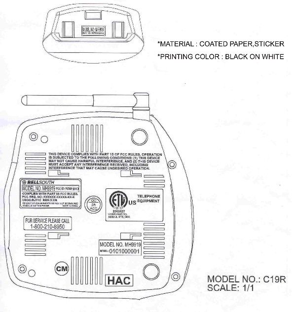
ID Label/Location Info
FCC ID : PIZMH9910 FCC ID LOCA TIO N
Internal Photos
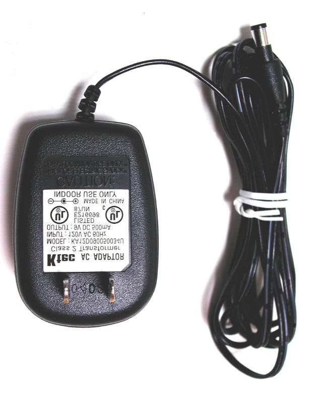
FC C ID : PIZM H 9910 M echanical C onst r uct i on Of H a ndset N u mber 1 172305- 10.J P G FC C ID : PIZM H 9910 M echanical C onst r uct i on Of H a ndset N u mber 2 172305- 11.J P G FC C ID : PIZM H 9910 M echanical C onst r uct i on Of H a ndset N u mber 3 172305- 12.J P G FC C ID : PIZM H 9910 R e a r s i d e o f M a i n B o a r d O f H a n d s e t N u m b e r 4 172305- 13.J P G FC C ID : PIZM H 9910 F r o n t s i d e o f M a i n B o a r d O f H a n d s e t N u m b e r 5 172305- 14.J P G FC C ID : PIZM H 9910 M echanical C onst r uct i on Of B ase St at ion N u mber 6 172305- 04.J P G FC C ID : PIZM H 9910 M echanical C onst r uct i on Of B ase St at ion N u mber 7 172305- 05.J P G FC C ID : PIZM H 9910 Front side of M a in B o ard Of B ase St at ion N u mber 8 172305- 06.J P G FC C ID : PIZM H 9910 R ear side of M a in B o ard Of B ase St at ion N u mber 9 172305- 07.J P G FC C ID : PIZM H 9910 F r o n t s i d e o f A d a p t e r N u m b e r 1 0 172305- 15.J P G FC C ID : PIZM H 9910 R e a r s i d e o f A d a p t e r N u m b e r 1 1 172305- 16.J P G FC C ID : PIZM H 9910 Telephone Line Number 12 172305- 19.J P G
Operational Description
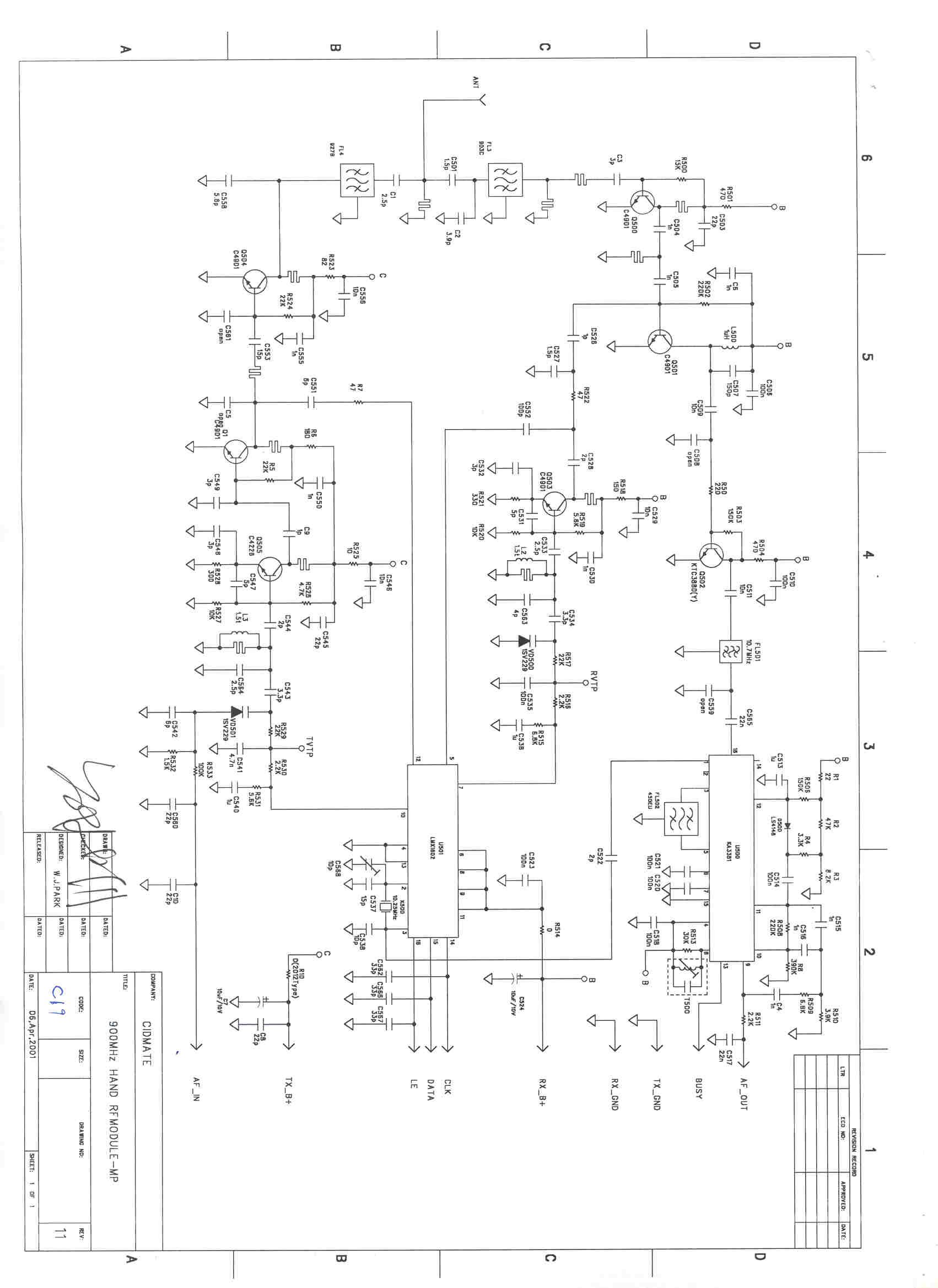
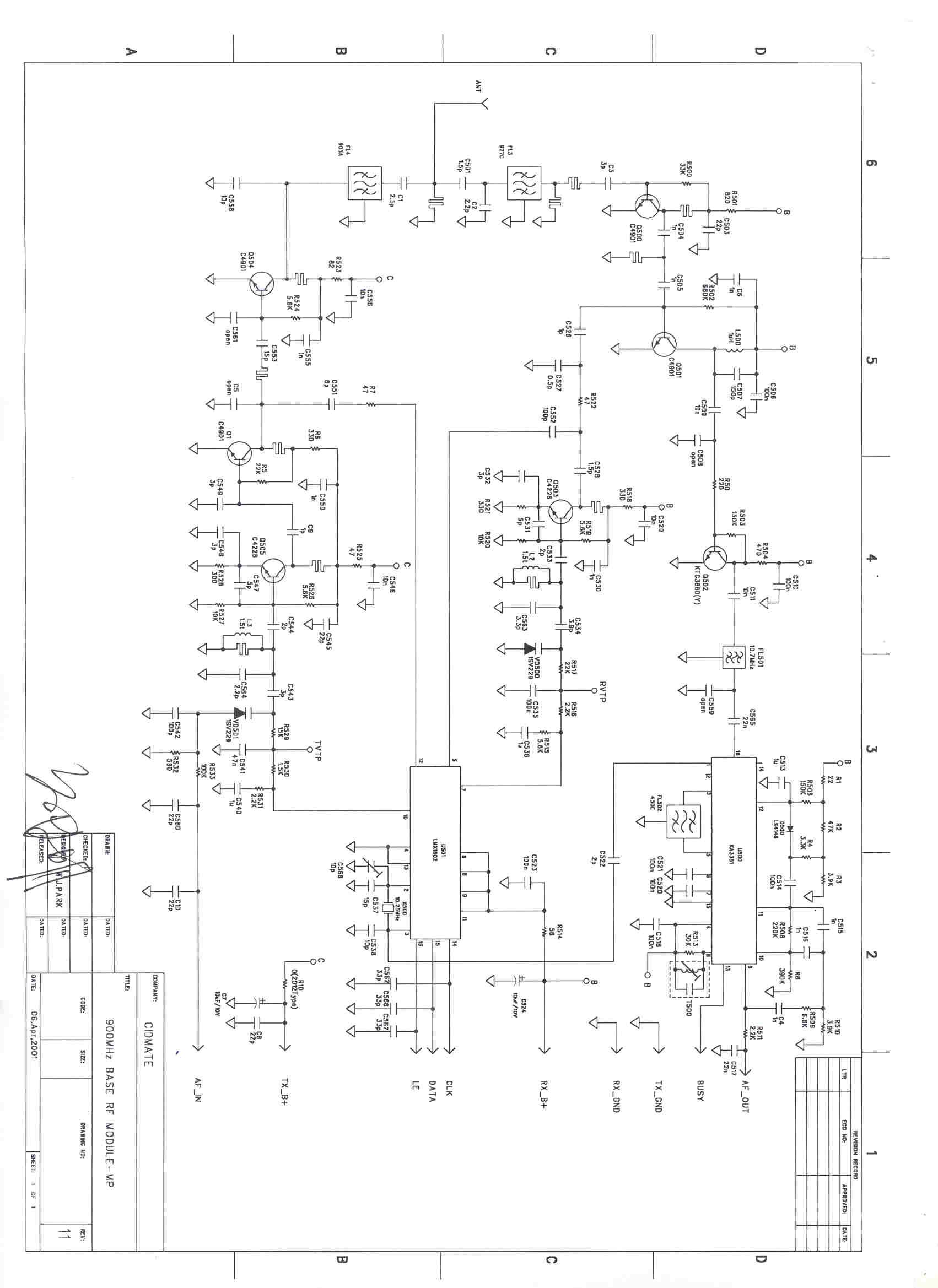
CIDMATE International Technology Inc. 3F-B, No. 58, Sec. 1, Minsheng E. Rd., Taipei, Taiwan 104, R.O.C. Tel: 886-2- 2521-8658 Fax: 886-2-2561-6624 Email: [email protected] FCC ID : PIMH9910 TECHNICAL DESCRIPTION Content HANDSET 1 RF/Audio Section 1.1 Receiver 1.2 Transmitter 1.3 Duplexer 1.4 Alerter 1.5 Headset microphone 2 MCU 2.1 Battery Detect 2.2 Carrier Detection BASE 3 RF/Audio Sections 4 Telephone Network 4.1 Telephone Interface 4.2 Ring Detect 4.3 Sidetone Cancellation Network 5 MCU 5.1 Charging Network 5.2 Carrier Detection CIDMATE International Technology Inc. 3F-B, No. 58, Sec. 1, Minsheng E. Rd., Taipei, Taiwan 104, R.O.C. Tel: 886-2- 2521-8658 Fax: 886-2-2561-6624 Email: [email protected] HANDSET 1. RF/Audio Section The radio link Handset and Base is full duplex at 902/928 MHz with the 40 channels. FM modulation is used for the link. The 1 st IF frequency is 10.7MHz and the 2 nd IF frequency is 450KHz. The operating frequency for the cordless phone is selected from one of the following channels and controlled by the synthesizer U501 that is programmed by the MCU. This section is common to both handset and base as the same ICs are used LMX1602(U501), KA3361(U500) is made up of dual serial input PLL frequency synthesizer with 1000MHz prescaler. KA3361 is a narrow-band IF detector IC. 1.1 Receiver The receiver section is made of double conversion with 10.7MHz as the first and second IF. Rx signal from the duplexer circuit is amplified by a Low Noise RF transistor and passed to a Mixer (Q500), and it is converted to 10.7MHz IF and it is then double converted to 405KHz IF in the internet mixer of U500. Voice/data signal is demodulated and output from pin9 of U500. The demodulated signal is then divided into two paths, a path is fed into the data amplifier Q606, Q605. The other path will go through a de-emphasized amplifier and an expander in IC11B. Recovered signal can be muted by the pin 13 of IC11B, the volume level of the signal can be controlled by the knob switch SW1. 1.2 Transmitter Audio signal (from Microphone for headset/Tip & Ring for base) is first fed into the amplifier and compressor inside IC11A. The signal will pass through a limiter. The AGC and the limiter have the property to limit the maximum signal that feed into the transmitter so that the RF deviation is limited. The transmitter section mainly divided into two parts. They are the voice/data modulator and the Tx power amplifier. The voltage-controlled oscillator VCO operated at the Tx frequency controlled by the synthesizer is modulated by the audio and data signals. Modulated signal is amplified by the RF amplified and sending the signal to the duplexer for radiation by the antenna. 1.3 Duplexer Two band-pass filters are matched to use as duplexer. The function of the duplexer is to multiplex the transmitting and receiving signals to a common antenna while providing isolation and rejection of interference and other spurious signals. CIDMATE International Technology Inc. 3F-B, No. 58, Sec. 1, Minsheng E. Rd., Taipei, Taiwan 104, R.O.C. Tel: 886-2- 2521-8658 Fax: 886-2-2561-6624 Email: [email protected] 1.4 Alerter The alerting signals include the following: Ringing, Paging, Key beep and Low battery warning tone. These tones are generated by the MCU to the alerter through the driving circuit formed Q608 and the associated components. 1.5 Headset microphone The condenser microphone is in the headset and it biased by the resistor R621. The signal is applied to the amplifier inside IC 11A 2. MCU 2.1 Battery Detect The voltage detector is composed of IC 12 that is used to detect battery low condition. The detecting accuracy of the voltage detector is +/- 0.2V. The detect pin BAT-LOW is connected to the pin 70 of MCU. 2.2 Carrier Detection This 40 channels cordless has the features of auto-scanning. This is done by the detection of the RSSI at pin 71 of MCU of handset. During PHONE on or CHANNEL changing, the MCU will select the clearest channel for the RF communication. CIDMATE International Technology Inc. 3F-B, No. 58, Sec. 1, Minsheng E. Rd., Taipei, Taiwan 104, R.O.C. Tel: 886-2- 2521-8658 Fax: 886-2-2561-6624 Email: [email protected] BASE 3. RF/Audio sections The operation of the RF/Audio section is similar to that of the handset. 4. Telephone Network 4.1 Telephone interface Fuse FUSEx is for over-voltage protection. Relay RL1 controls the on/off hook state and pulse dialing. The Tip& Ring are isolated from the base circuit by the transformer T1, relay RL1. 4.2 Ring Detect When ring signal is present on the Tip Ring, and envelope waveform of the ring pattern will transfer to pin 69 of MCU by the Q1. The MCU will read this waveform and determine whether it will send ringer command. 4.3 Sidtone Cancellation Network The sidetone cancellation is a hybrid circuit of the Tx and Rx paths of the telephone circuit formed by the Q12. 5. MCU 5.1 Charging Network Base charging circuit provides a DC current for handset battery. Resistor R12P controls the current flow. 5.2 Carrier Detection This is similar to the handset counterpart.
Schematics
C15CB1A2.SCH-1 - Tue Jan 08 16:12:41 2002
Schematics
C15CH1A1.SCH-1 - Tue Jan 08 14:58:47 2002
Test Report
FCC TEST REPORT Report No. : F172305 SPORTON International Inc. TEL : 886-2-2696-2468 FAX : 886-2-2696-2255 FCC TEST REPORT for 47 CFR, Part 15, Subpart C Equipment : 900MHz CORDLESS PHONE Model No. : C19R, MH9919xx, I9919xx, M42003xx, M72003xx (x could be blank, numbers or alphabetical characters) FCC ID : PIZMH9910 Filing Type : Certification Applicant : CIDMATE INTERNATIONAL TECHNOLOGY INC. 3F, No. 58, Sec. 1, Minsheng E. Rd., Taipei, Taiwan 104, R.O.C. † The test result refers exclusively to the test presented test model / sample. † Without the written authorization of the test lab., the Test Report may not be copied. † Certificate or Test Report must not be used by the applicant to claim the product in this test report endorsement by NVLAP or any agency of U.S. government. SPORTON International Inc. 6F, No.106, Sec. 1, Hsin Tai Wu Rd., Hsi Chih, Taipei Hsien, Taiwan, R.O.C. FCC TEST REPORT Report No. : F172305 SPORTON International Inc. FCC ID : PIZMH9919 TEL : 886-2-2696-2468 Page No. : i FAX : 886-2-2696-2255 Issued Date : Nov. 28, 2001 Table of Contents History of this test report.........................................................................................................................ii CERTIFICATE OF COMPLIANCE..............................................................................................................1 1. General Description of Equipment under Test......................................................................................2 1.1. Applicant.......................................................................................................................................................................................2 1.2. Manufacturer.................................................................................................................................................................................2 1.3. Basic Description of Equipment under Test..................................................................................................................................2 1.4. Feature of Equipment under Test.................................................................................................................................................2 1.5. Channel Table of Equipment under Test.......................................................................................................................................3 1.6. Statement of the EUT to comply with requirement of 15.214 (d)...................................................................................................4 2. Test Configuration of Equipment under Test........................................................................................5 2.1. Test Manner..................................................................................................................................................................................5 2.2. Description of Test System...........................................................................................................................................................5 2.3. Band edges measurement............................................................................................................................................................6 3. General Information of Test..................................................................................................................8 3.1. Test Facility...................................................................................................................................................................................8 3.2. Standard for Methods of Measurement.........................................................................................................................................8 3.3. Test in Compliance with................................................................................................................................................................8 3.4. Frequency Range Investigated.....................................................................................................................................................8 3.5. Test Distance................................................................................................................................................................................8 4. Test of Conducted Powerline................................................................................................................9 4.1. Major Measuring Instruments........................................................................................................................................................9 4.2. Test Procedures..........................................................................................................................................................................10 4.3. Typical Test Setup Layout of Conducted Powerline....................................................................................................................11 4.4. Test Result of AC Powerline Conducted Emission......................................................................................................................12 4.5. Photographs of Conducted Powerline Test Configuration...........................................................................! 5. Test of Radiated Emission..................................................................................................................15 5.1. Major Measuring Instruments......................................................................................................................................................15 5.2. Test Procedures..........................................................................................................................................................................16 5.3. Typical Test Setup Layout of Radiated Emission........................…
Text truncated - open the document above for the full version.
Test Setup Photos
FCC TEST REPORT Report No. : F172305 1.1. Photographs of Conducted Powerline Test Configuration z The photographs show the configuration that generates the maximum emission. FRONT VIEW REAR VIEW SPORTON International Inc. FCC ID : PIZMH9910 TEL : 886-2-2696-2468 Page No. : 1 of 4 FAX : 886-2-2696-2255 Issued : Nov, 28, 2001 FCC TEST REPORT Report No. : F172305 SIDE VIEW SPORTON International Inc. FCC ID : PIZMH9910 TEL : 886-2-2696-2468 Page No. : 2 of 4 FAX : 886-2-2696-2255 Issued : Nov, 28, 2001 FCC TEST REPORT Report No. : F172305 1.2. Photographs of Radiated Emission Test Configuration z The photographs show the configuration that generates the maximum emission. Handset FRONT VIEW REAR VIEW SPORTON International Inc. FCC ID : PIZMH9910 TEL : 886-2-2696-2468 Page No. : 3 of 4 FAX : 886-2-2696-2255 Issued : Nov, 28, 2001 FCC TEST REPORT Report No. : F172305 Base FRONT VIEW REAR VIEW SPORTON International Inc. FCC ID : PIZMH9910 TEL : 886-2-2696-2468 Page No. : 4 of 4 FAX : 886-2-2696-2255 Issued : Nov, 28, 2001
Contact Information
Applicant
Beryl Liu(Sales Asst. Manager)
Test Firm
SPORTON International IncKathy Lin
Technical Specifications
| # | Rule Parts | Frequency Range | Power Output |
|---|---|---|---|
| 2 | 15C | 925.375 MHz - 927.325 MHz | - |
Other Applications from CIDMATE International Technology Inc.
PIZGH9492
Mar 28, 20042.4 GHz Analog Cordless Phone with CID and DAM
Equipment Class
DXX - Part 15 Low Power Communication Device Transmitter
PIZGH9764
Mar 24, 20042.4GHz DSST Multi-Handset w/ CID+DAM
Equipment Class
DTS - Digital Transmission System
PIZXG34001
Aug 17, 20032.4GHz ANALOG CORDLESS PHONE
Equipment Class
DXX - Part 15 Low Power Communication Device Transmitter
PIZMINI1
Jul 24, 20032.4 GHz Analog Cordless Telephone with CID
Equipment Class
DXX - Part 15 Low Power Communication Device Transmitter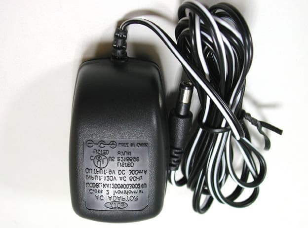
PIZXG32010
Jul 09, 20032.4GHz ANALOG CORDLESS PHONE
Equipment Class
DXX - Part 15 Low Power Communication Device Transmitter