PJF-05000TXSMART TRAC Digital Audio Monitor
Baby's Journey, Inc.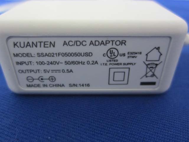
Click to zoom
Application Details
- Equipment Class
- DSS - Part 15 Spread Spectrum Transmitter
- Date of Grant
- Jun 22, 2014
- Application Purpose
- Original Equipment
- Date of Application
- Jun 22, 2014
- Equipment Note
- SMART TRAC Digital Audio Monitor
- Frequency Range
- 2406.00000000 - 2478.00000000
- Company
- Baby's Journey, Inc.
- Country
- United States
Documents & Files
Document Text
Text extracted from the exhibit documents filed with the FCC. Open a document above to read the original.
Users Manual
• Battery: Lithium-ion 3.7V Set Baby Birthday Screen displays “BABY BDAY” and the month digits flash. Use Up/Down buttons to increase. Use Right button to advance. The day digits flash. Use Up to increase. Use Right button to Save and advance to Baby Name. Sleep Press Start/Stop to start the timer counting. "Start" will flash while timer is actively running. Note: Other data cannot be entered while a timer is running. Press Start/Stop to stop the timer; press Memory to save. Note: Entries less than 1 minute will not save. Change display to Sleep and press Select button to select. Screen displays the last data, or it displays “0 00” and “Duration”. Memory Baby Tracker holds 12 inputs for Feeding, Sleep and Medicines, as well as the last 14 inputs for Diapers. While in a certain category (e.g. Feeding), press Memory to see past saved data. “Memory” will show in the upper left when viewing past saved data. Use Left/Right buttons to move through past entries. Press Select to exit Memory and start a new entry in the category you have selected or press Mode to exit memory and navigate to a different category. Baby Tracker Overview You can keep track of Feedings (Breast/ Bottle), Diapers, Sleep, and Medicines while using the Baby Tracker. Use Mode button to move between the categories and Select button to select them. Use Start/Stop for Sleep and Breastfeeding timers and to log a time for any data entry. Talkback microphone Power LED Sound and Volume Indicator Lights Volume keys Pair button Reset button USB Charging port Speaker Power LED Power and Screen On/Off Navigation Select Speaker Microphone Pair button Power On/Off switch On back: Stand Belt Clip On back: AC port Digital Audio Monitor Smart Trac Medicines Medicines mode allows you to set an alert reminding you when to provide the next dose. It also saves that alert in Memory. Press Start/Stop to log the current time. Press Memory to save. Press Start/Stop to turn off alert once it has sounded. Change display to Medicines and press Select button to select. Screen displays the last data saved, or it displays “min” and “00” flashes. Use Left/Right buttons to toggle to hours. Use Up/Down to set medicine alert. Diapers Press Start/Stop to log the time; press Memory to save. BM “00” flashes. Use Up/Down to change. Change display to Diapers and press Select button to select. Screen displays the last data saved, or it displays“00” Wet “00” BM. Wet “00” flashes. Use Up/Down buttons to change. Use Left/Right buttons to toggle. Feeding - Bottle Select “b” for bottle; “00” flashes. Press Start/Stop to log time of feeding; press Memory to save the entry. Use Up/Down to change the number of ounces consumed. Within Feeding, Toggle “L” (left breast), “R” (right breast), or “b” (bottle) using Left/Right buttons. Feeding - Breast Change display to Feeding and press Select button to select. Screen displays the last data saved, or it displays “L 00 min”. Toggle “L” (left breast), “R” (right breast), or “b” (bottle) by using the Left/Right buttons. Press Start/Stop to start the timer counting. "Start" will flash while timer is actively running. Note: Other data cannot be entered while a timer is running. Press Start/Stop to stop the timer; press Memory to save. Note: Entries less than 1 minute will not save. Use Set Date Screen displays “SET DATE” and the month digits flash. The day digits flash. Use Up/Down buttons to increase. Use Right button to Save and advance to Baby Birthday. Use Up/Down buttons to increase. Use Right button to advance. Set Time Setup Use Mode button to highlight Settings and press Select button to select. Screen displays“SET TIME” and hour digits flash. Use Up/Down buttons to increase. Use Right button to advance. Minute digits flash. Use Up/Down buttons to increase. Use Right button to advance. AM/PM flashes. Use Up/Down buttons to change. Use Right button to Save and advance to Set Date. Place Baby Unit on a flat surface and use cord clips. To prevent entanglement, any cord must be 3 feet away from children’s reach. Using your Audio Monitor Placement Talk Back With both units on, push and hold the Talk button on the Parent Monitor. Your baby will hear what you are saying until you release the Talk button. Stand The back of Parent Monitor features a flip-out stand that keeps monitor at ideal viewing angle on flat surfaces. WARNING! Strangulation Hazard: Children have STRANGLED in cords. Keep this cord out of the reach of children (more than 3 ft. (0.9 m) away). 3 ft. NOTES: User Guide is color printed as Front/Back sheet with accordion folds. 11 “pages” per side. Grey lines are Cut and fold lines = DO NOT PRINT. Scale - 1:1 AUDIO MONITOR USER GUIDE REV N April 23, 2014 What’s mHealth? Welcome to your Smart Trac Monitor AT&T’s line of mHealth monitors are designed to keep you and your baby connected and collect their key milestones and events. mHealth, or mobile health, is the use of mobile devices to aid in health and wellness. Whether you want to keep track of feedings and diapers or monitor medicines and sleep patterns, with AT&T mHealth, you can quickly and easily keep all these data in the palm of your hand. What’s Included? m health Parent Monitor (1x) Baby Unit (1x) USB power adapter for rechargeable battery (1x) Cord Clips (6x) AC power adapter (1x) NOTE:This equipment has been tested and found to comply with the limits for a Class B digital device, pursuant to part 15 of the FCC Rules. These limits are designed to provide reasonable protection against harmful interference in a residential installation. This equipment gener- ates, uses and can radiate radio frequency energy and, if not installed and used in accor- dance with the instructions, may cause harmful interference to radio communications. However, there is no guarantee that interference will not occur in a particular installation. If this equipment does cause harmful interference to radio or can be determined by turning the equipment off and on, the user is encourag…
Text truncated - open the document above for the full version.
External Photos
EXHIBIT B - EUT EXTERNAL PHOTOGRAPHS EUT—All View EUT— Front View EUT— Rear View EUT— Left Side View EUT— Right Side View EUT- Adapter View EUT- Adapter Label View
ID Label/Location Info
EXHIBIT A - FCC ID LABELING AND LOCATION FCC ID Label Proposed FCC ID Label Location The label shown shall be permanently affixed at a conspicuous location on the device and be readily visible to the user at the time purchase (Labeling requirements per 2.925) Label Here
Internal Photos
EXHIBIT C - EUT INTERNAL PHOTOGRAPHS EUT- Bottom Cover Off View EUT- Uncover View EUT- Cover Off View EUT- AntennaView Antenna EUT- Main Board Top View EUT- Main Board Top Shielding Off View EUT- Main Board Bottom View EUT- Power Board Top View EUT- Power Board Bottom View
Test Report
Note: This test report is prepared for the customer shown above and for the device described herein. It may not be duplicated or used in part without prior written consent from Bay Area Compliance Laboratories Corp. (Dongguan). This report is valid only with a valid digital signature. The digital signature may be available only under the Adobe software above version 7.0. FCC PART 15.247 TEST REPORT For Baby’s Journey, Inc. 999 Main Street, Unit 703, Pawtucket, Rhode Island, United States Report Type: Original Report Product Type: SMART TRAC Digital Audio Monitor (Baby Unit) Test En gineer: Ares Liu Re port Number: R2DG140305003-00A Re port Date: 2014-05-22 Reviewed By: Sula Huang RF Engineer Test Laboratory: Bay Area Compliance Laboratories Corp. (Dongguan) No.69 Pulongcun, Puxinhu Industrial Zone, Tangxia, Dongguan, Guangdong, China Tel: +86-769-86858888 Fax: +86-769-86858891 www.baclcorp.com.cn FCC ID: PJF-05000TX Bay Area Compliance Laboratories Corp. (Dongguan) Report No.: R2DG140305003-00A FCC Part 15.247 Page 2 of 36 TABLE OF CONTENTS GENERAL INFORMATION ....................................................................................................................................... 4 PRODUCT DESCRIPTION FOR EQUIPMENT UNDER TEST (EUT) ..................................................................................... 4 OBJECTIVE ................................................................................................................................................................... 4 TEST METHODOLOGY .................................................................................................................................................. 4 TEST FACILITY ............................................................................................................................................................. 4 SYSTEM TEST CONFIGURATION .......................................................................................................................... 5 DESCRIPTION OF TEST CONFIGURATION ...................................................................................................................... 5 EUT EXERCISE SOFTWARE .......................................................................................................................................... 5 EQUIPMENT MODIFICATIONS ....................................................................................................................................... 5 EXTERNAL CABLE ........................................................................................................................................................ 5 BLOCK DIAGRAM OF TEST SETUP ................................................................................................................................ 6 SUMMARY OF TEST RESULTS ............................................................................................................................... 7 FCC §15.247 (i) & §1.1310 & §2.1091- MAXIMUM PERMISSIBLE EXPOSURE (MPE) ......................................... 8 APPLICABLE STANDARD .............................................................................................................................................. 8 FCC §15.203 - ANTENNA REQUIREMENT ............................................................................................................. 9 APPLICABLE STANDARD .............................................................................................................................................. 9 ANTENNA CONNECTOR CONSTRUCTION ...................................................................................................................... 9 FCC §15.207 (a) – AC LINE CONDUCTED EMISSIONS ..................................................................................... 10 APPLICABLE STANDARD ............................................................................................................................................ 10 MEASUREMENT UNCERTAINTY .................................................................................................................................. 10 EUT SETUP ................................................................................................................................................................ 10 EMI TEST RECEIVER SETUP ....................................................................................................................................... 11 TEST PROCEDURE ...................................................................................................................................................... 11 CORRECTED AMPLITUDE & MARGIN CALCULATION ................................................................................................. 11 TEST EQUIPMENT LIST AND DETAILS ......................................................................................................................... 12 TEST RESULTS SUMMARY .......................................................................................................................................... 12 TEST DATA ................................................................................................................................................................ 12 FCC §15.209, §15.205 & §15.247(d) - SPURIOUS EMISSIONS ............................................................................. 15 APPLICABLE STANDARD ............................................................................................................................................ 15 MEASUREMENT UNCERTAINTY .................................................................................................................................. 15 EUT SETUP ................................................................................................................................................................ 15 EMI TEST RECEIVER & SPECTRUM ANALYZER SET…
Text truncated - open the document above for the full version.
Test Setup Photos
EXHIBIT D - TEST SETUP PHOTOGRAPHS Conducted Emissions - Front View Conducted Emissions –Side View Radiated Emissions Below 1GHz - Front View Radiated Emissions Below 1GHz –Rear View Radiated Emissions Above 1GHz - Front View Radiated Emissions Above 1GHz –Rear View
Contact Information
Applicant
Steve Gibree(President)
Test Firm
Bay Area Compliance Laboratory Corp. (Shenzhen)John Chan
Technical Specifications
| # | Rule Parts | Frequency Range | Power Output |
|---|---|---|---|
| 1 | 15C | 2.41 GHz - 2.48 GHz | 31.30 mW |
Other Applications from Baby's Journey, Inc.
PJF-05010RX
Jan 27, 2015SMART SYNC 5 inches Internet Viewable Touch Screen Video Monitor
Equipment Class
DTS - Digital Transmission System
PJF-05020RX
Jan 27, 2015SMART LINK 4.3 inches Touch Screen Video Monitor
Equipment Class
DTS - Digital Transmission System
PJF-2146RX
Sep 28, 20142.4 inch color video monitor
Equipment Class
DSS - Part 15 Spread Spectrum Transmitter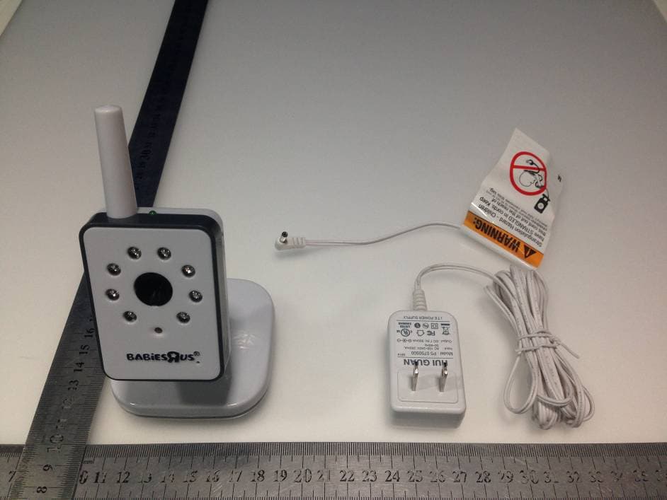
PJF-2313TX
Sep 28, 20145 inch color flatscreen video monitor
Equipment Class
DSS - Part 15 Spread Spectrum Transmitter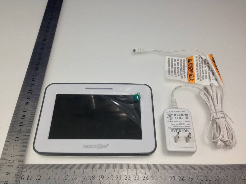
PJF-2313RX
Sep 25, 20145 inch color flatscreen video monitor
Equipment Class
DSS - Part 15 Spread Spectrum Transmitter