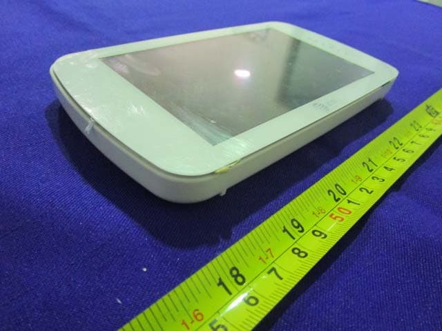
PJF-2313TX5 inch color flatscreen video monitor
Baby's Journey, Inc.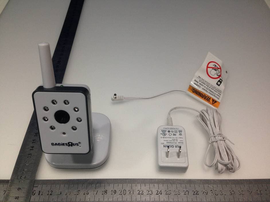
Click to zoom
Application Details
- Equipment Class
- DSS - Part 15 Spread Spectrum Transmitter
- Date of Grant
- Sep 28, 2014
- Application Purpose
- Original Equipment
- Date of Application
- Sep 27, 2014
- Equipment Note
- 5 inch color flatscreen video monitor
- Frequency Range
- 2409.00000000 - 2469.80000000
- Company
- Baby's Journey, Inc.
- Country
- United States
Documents & Files
Document Text
Text extracted from the exhibit documents filed with the FCC. Open a document above to read the original.
Users Manual
Features & Components 5” Color Flatscreen Video Monitor User Guide5F62313 • Please read the following instructions and safety warnings before you install the Video Monitor. • Please retain these instructions for future reference • Tool needed: Phillips Head Screwdriver (not included). • Additional camera(s) (sold separately). • For use with children from birth and up. Important guidelines for installing your Video Monitor Getting Started The Monitor and Camera use a 2.4 GHz radio frequency to synchronize to each other. The range for this frequency may be affected by environmental conditions in your home such as; walls, floors, ceilings, Wi-Fi routers, microwave ovens, cordless phones, Bluetooth devices, home computers, among other electronic devices. It is recommended to keep your Monitor away from these types of devices at least 5 feet. If the signal is weak, try moving the Monitor and/or Camera to different positions in the rooms. 1 Connect Camera to AC outlet. 2 To turn ON, slide the ON/OFF switch to the ON position. The Power ON Indicator will illuminate green. 3 To turn OFF, slide the ON/OFF switch to the OFF position. Important Safety Warnings Monitor Camera Set-up of your Camera Once you have successfully established a connection between the Camera and Monitor, it is time to determine a safe location to place the Camera. IMPORTANT: Never place Camera or cords within 3 feet (0.9 m) of children’s reach. Determine a safe location for the Camera that will provide the best view of your baby. Place the Camera on a flat surface, such as a dresser, bureau, or shelf or wall mount it using the supplies provided. If you choose to wall mount the Camera, ALWAYS use the security clips provided to secure the cord to the wall. Important Safety Warnings To prevent cord entanglement and strangulations: • Do not place the Camera or AC adaptor cord within reach of children. • Do not place the Camera or AC adaptor cord in, or attach it to, a crib or playpen. • Always fasten the AC adaptor cord of the Camera on the wall with the security clips provided. • Never use extension cords with AC adaptors. Use only AC adaptors provided. Important Safety Instructions: • Adult assembly is required. Keep small parts away from child’s reach. • This product is not a toy. Do not allow children to play with it. • This Video Monitor is not a substitute for responsible adult supervision. • Test the Video Monitor and all its functions so that you are familiar with it prior to actual use. • When the power adaptor is plugged into an electrical outlet, do not touch the exposed end. Camera: 1 Battery Installation: Install the rechargeable battery included. 2 Connect Monitor to AC outlet. 3 To turn ON, press and hold the Power ON/OFF button for 3 seconds until “Hello” screen disappears. 4 Now that the Monitor and Camera are turned on, video captured by the Camera will appear on the video screen. 5 To turn OFF, press and hold the Power ON/OFF button for 3 seconds until the “Goodbye” screen disappears. IMPORTANT: The Camera and Monitor are already paired; in the event that the connection is lost you will need to pair the Camera to the Monitor. To pair, follow the steps provided under “Using Video Monitor” section. Monitor: Instructions continued on reverse side. Battery Installation & Use Strangulation Hazard - Children have STRANGLED in cords. Keep this cord out of the reach of children (more than 3 feet (0.9 m) away). WARNING! Security Clips (6)Wall AnchorScrewAC Adapters (2) Monitor Menu Icons Signal Level (5 Levels) Camera Selected (can pair up to 4 cameras, additional cameras sold separately) Battery Level or Charging Status (5 Levels) Night Vision Mode (Video changes to Black and White) Camera Scanning (scan up to 4 Cameras with each scan duration of 10 seconds) Volume Level Control (8 Levels) Brightness Level Control (8 Levels) Zoom Level Control (1x, 2x) Place the Camera and cords more than 3 feet (0.9m) away from your child Place the Camera and cords more than 3 feet (0.9m) away from your child Power ON Indicator/ Sound Level Indicator 5 inch Video Screen Power ON/OFF & Menu Button AC Adapter Jack Volume +/- Buttons & Menu Up/Down Brightness +/- Buttons & Menu Left/Right Zoom Control Button & Enter Video ON/OFF Button Antenna Speaker Stand Battery Compartment (for rechargeable battery) A B C D E F G H I J K L M A B C E F G D H I J K L Antenna Nighttime Infrared LED Lights Camera Lens Microphone Power ON Indicator Pair Button Power ON/OFF Switch AC Adapter Jack Wall Mount Notch Room Darkening Automatic Sensor N O P Q R S T U V Rechargeable Battery BATTERY WARNING! • ONLY use the rechargeable battery* provided. • ALWAYS keep battery away from children. • Clean battery and product contact prior to battery installation. • Do not short-circuit supply terminals. • ALWAYS remove battery if you do not intend to use the product for an extended period of time. Battery left in the unit may leak and cause damage. • Risk of explosion if battery is replaced by an incorrect type. Discard leaky batteries immediately to avoid skin burns or other personal injury. Discard batteries properly according to local regulations. • Change battery when unit no longer functions properly. • Recharge battery only under adult supervision. CAUTION: • Risk of explosion if battery is replaced by incorrect type. * To order a new rechargeable battery pack, visit WWW.BABIESRUS.COM. M Q S R T N O P U V FCC and IC Regulations FCC Part 15: This device complies with part 15 of the FCC Rules. Operation is subject to the following two conditions: (1) this device may not cause harmful interference, and (2) this device must accept any interference received, including interference that may cause undesired operation. Warning: Changes or modifications to this unit not expressly approved by the party responsible for compliance could void the user’s authority to operate the equipment. NOTE: This equipment has been tested and found to comply with the limits for a Class…
Text truncated - open the document above for the full version.
Cover Letter(s)
SCS-F18: Project and Product Certification Representative Authorization Letter Page 1 of 2 Rev 5.0 775 Montague Expressway Milpitas, CA 95035 Tel: 408-526-1188 Fax: 408-526-1088 Email: [email protected] Project and Product Certification Representative Authorization Letter Reason for Amendment (current / obsolete) Revision History Approved Date From To Initial Release (obsolete) 1.0 1.0 Nov-14-2006 Revised wording (obsolete) 1.0 2.0 Sept–25-2007 Updated company template (obsolete) 2.0 3.0 Jan-31-2012 Updated letter information (obsolete) 3.0 4.0 May-23-2014 Added FCC ID field (current) 4.0 5.0 Sept 16 2014 SCS-F18: Project and Product Certification Representative Authorization Letter Page 2 of 2 Rev 5.0 Baby’s Journey, Inc. 2014-7-30 To: SIEMIC, INC. 775 Montague Expressway, Milpitas, CA 95035 USA Dear Sir/Madam, Re: Product Certification Representative Authorization Letter We, Baby’s Journey, Inc . hereby authorize SIEMIC, Inc. to act as a Certification Body for certifying for the following project(s): FCC ID: PJF-2313TX 5” color flatscreen video monitor, 5F62313
Cover Letter(s)
775 Montague Expressway Milpitas, CA 95035 Tel: 408-526-1188 Fax: 408-526-1088 Email: [email protected] Confidentiality Request Letter Reason for Amendment (current / obsolete) Revision History Approved Date From To Initial Release (obsolete) 1.0 1.0 Nov-14-2006 Adding CFR 2.459 (obsolete) 1.0 2.0 August – 11 - 2008 Updated company template & Added text box (current) 2.0 3.0 Jan-31-2012 SCS-F19: Confidentiality Request Letter Page 1 of 2 Rev 3.0 Baby’s Journey, Inc. 2014-07-30 To: Federal Communications Commission Authorization and Evaluation Division 7435 Oakland Mills Road Columbia, MD Subject: Permanent Confidentiality Request for FCC ID: PJF-2313TX 5” color flatscreen video monitor, 5F62313 We hereby request confidential treatment of information accompanying this application as outlined below: - B lock Diagram - Schematics - Operational Description The above materials contain trade secrets and proprietary information not customarily released to the public. The public disclosure of these materials may be harmful to the applicant and provide unjustified benefits to its competitors. The applicant understands that pursuant to Section 0.457 & 0.459 of the Rules, disclosure of this application and all accompanying documentation will not be made before the date of the Grant for this application. Sincerely, S ignature Steve Gibree / President E-mail: [email protected] Phone: 4017424031 Fax: 7742330582 Address 22 Shore Rd, Narragansett, Rhode Island, United States SCS-F 19: Confidentiality Request Letter Page 2 of 2 Rev 3.0
Cover Letter(s)
Baby’s Journey, Inc. Equipment Name: 5” color flatscreen video monitor FCC ID: PJF-2313TX Mo del: 5F62313 Hopping description: Divide the bandwidth from 2409-2469.8 to 18 frequency points, each bandwidth with 3.4MHz. The system selects 1 frequency points from 18 frequency points. The transmitting point is selected randomly, and shared the same priority. The max frequency hopping time is 400ms. Hopping Sequence: For example, for the hop pattern of 2419.2, 2451.8, 2437.2, 2409, 2445, 2458.6, 2412.4, 2455.2, 2466.4, 2415.8, 2430.4, 2463, 2423.6, 2448.4, 2427, 2433.8, 2469.8, 2440.6 The sequential hops is no any order can follow, is completely random.
ID Label/Location Info
5” color flatscreen video monitor FCC ID: PJF-2313TX Model Number: 5F62313 Made in China This device complies with Part 15 of the FCC Rules. Operation is subject to the following two conditions: (1) this device may not cause harmful interference, and (2) this device must accept any interference received, including interference that may cause undesired operation.
ID Label/Location Info
Label Location Proposed Label Location on EUT
Internal Photos
Antenna Wireless Module
RF Exposure Info
FCC ID : PJF-2313TX RF EXPOSURE EVALUATION According to FCC 1.1310: The criteria listed in the following table shall be used to evaluate the environment impact of human exposure to radio frequency(RF) Radiation as specified in §1.1307(b) Limits for Maximum Permissible Exposure(MPE) Frequency Range(MHz) Electric Field Strength(V/m) Magnetic Field Strength(A/m) Power Density(mW/cm 2 ) Average Time (A) Limits for Occupational/Control Exposures 300-1500 -- -- F/300 6 1500-100000 -- -- 5 6 (B) Limits for General Population/Uncontrol Exposures 300-1500 -- -- F/1500 6 1500-100000 -- -- 1 30 11.1 Friis transmission formula: Pd=(Pout*G)\(4*pi*R 2 ) Where Pd= Power density in mW/cm 2 Pout=output power to antenna in mW G= Numeric gain of the antenna relative to isotropic antenna Pi=3.1416 R= distance between observation point and center of the radiator in cm Pd the limit of MPE, 1mW/cm 2 . If we know the maximum gain of the antenna and total power input to the antenna, through the calculation, we will know the distance where the MPE limit is reached. 11.2 Measurement Result Antenna gain:0dBi Mode Channel Frequency (MHz) Max Output Peak power (dBm) Output Peak power (mW) Antenna Gain (dBi) Numeric Power density at 20cm (mW/ cm 2 ) Power density Limits (mW/cm 2 ) GFSK 2409 13.62 23.014 1 0.0046 1 GFSK 2437.2 12.95 19.724 1 0.0039 1 GFSK 2469.8 11.30 13.490 1 0.0027 1
Test Report
TRF No:FCC 15.247/A Page 1 of 48 Report No: ES140626270E Shenzhen EMTEK Co.,Ltd. Building 69, Majialong Industry Zone, Nanshan District, Shenzhen,Guangdong,China www.emtek.com.cn Tel: +86-755-2695 4280 Fax: +86-755-2695 4282 Access to the World ELECTROMAGNETIC EMISSIONS COMPLIANCE REPORT INTENTIONAL RADIATOR CERTIFICATION TO FCC PART 15 SUBPARTC REQUIREMENT OF 5” color flatscreen video monitor MODEL No.: 2313TX FCC ID: PJF-2313TX Trademark: N/A REPORT NO: ES140626270E ISSUE DATE: July 17, 2014 Prepared for Baby’s Journey, Inc. 22 Shore Rd, Narragansett, Rhode Island, United States Prepared by SHENZHEN EMTEK CO., LTD Bldg 69, Majialong Industry Zone, Nanshan District, Shenzhen, Guangdong, China TEL: 86-755-26954280 FAX: 86-755-26954282 TRF No:FCC 15.247/A Page 2 of 48 Report No: ES140626270E Shenzhen EMTEK Co.,Ltd. Building 69, Majialong Industry Zone, Nanshan District, Shenzhen,Guangdong,China www.emtek.com.cn Tel: +86-755-2695 4280 Fax: +86-755-2695 4282 Access to the World VERIFICATION OF COMPLIANCE Applicant: Baby’s Journey, Inc. 22 Shore Rd, Narragansett, Rhode Island, United States Manufacturer: Easton Ward Electronics Technology Limited Room B3, Block B, 15/F, Wong King Industrial Building, 2-4 Tai Yau Street, San Po Kong, Kowloon, HK Product Description: 5” color flatscreen video monitor Model Number: 2313TX Serial Number: N/A File Number: ES140626270E We hereby certify that: The above equipment was tested by SHENZHEN EMTEK CO., LTD. The test data, data evaluation, test procedures, and equipment configurations shown in this report were made in accordance with the procedures given in ANSI C63.4 (2009) and the energy emitted by the sample EUT tested as described in this report is in compliance with conducted and radiated emission limits of FCC Rules Part 15.247. The test results of this report relate only to the tested sample identified in this report. Date of Test : July 5, 2014 to July 17, 2014 Prepared by : Joe Xia/Editor Reviewer : June Xie/Supervisor Approve & Authorized Signer : Lisa Wang/Manager TRF No:FCC 15.247/A Page 3 of 48 Report No: ES140626270E Shenzhen EMTEK Co.,Ltd. Building 69, Majialong Industry Zone, Nanshan District, Shenzhen,Guangdong,China www.emtek.com.cn Tel: +86-755-2695 4280 Fax: +86-755-2695 4282 Access to the World Ta b l e o f C o n t e n t s 1. GENERAL INFORMATION ................................................................................................. 5 1.1 Product Description ................................................................................................................................. 5 1.2 Related Submittal(s) / Grant (s)............................................................................................................... 5 1.3 Test Methodology ................................................................................................................................... 5 1.4 Special Accessories ................................................................................................................................. 5 1.5 Equipment Modifications ........................................................................................................................ 5 1.6 Test Facility ............................................................................................................................................. 6 2. System Test Configuration ...................................................................................................... 7 2.1 EUT Configuration .................................................................................................................................. 7 2.2 EUT Exercise .......................................................................................................................................... 7 2.3 Test Procedure ......................................................................................................................................... 7 2.4 Limitation ................................................................................................................................................ 7 2.5 Configuration of Tested System ............................................................................................................ 10 2.6 Equipment Used in Tested System ........................................................................................................ 10 2.7 Description of test modes ...................................................................................................................... 11 3. Summary of Test Results ....................................................................................................... 12 4. Conducted Emissions Test .................................................................................................... 13 4.1 Measurement Procedure: ....................................................................................................................... 13 4.2 Test SET-UP (Block Diagram of Configuration) .................................................................................. 13 4.3 Measurement Equipment Used: ............................................................................................................ 13 4.4 Conducted Emission Limit .................................................................................................................... 13 4.5 Measurement Result: ............................................................................................................................. 14 5. Radiated Emission Test ......................................................................................................... 16 5.1 Measurement Procedure ........................................................................................................................ 16 5.2 Test SET-UP (Block Diagram of Configuration) .................................................................................. 17 5.…
Text truncated - open the document above for the full version.
Test Setup Photos
Conducted Emissions Te s t Radiated Emission Te s t
Contact Information
Applicant
Steve Gibree(President)
Test Firm
EMTEK (Shenzhen) Co., Ltd.David Lee
Technical Specifications
| # | Rule Parts | Frequency Range | Power Output |
|---|---|---|---|
| 1 | 15C | 2.41 GHz - 2.47 GHz | 23.00 mW |
Other Applications from Baby's Journey, Inc.
PJF-05010RX
Jan 27, 2015SMART SYNC 5 inches Internet Viewable Touch Screen Video Monitor
Equipment Class
DTS - Digital Transmission System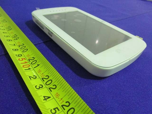
PJF-05020RX
Jan 27, 2015SMART LINK 4.3 inches Touch Screen Video Monitor
Equipment Class
DTS - Digital Transmission System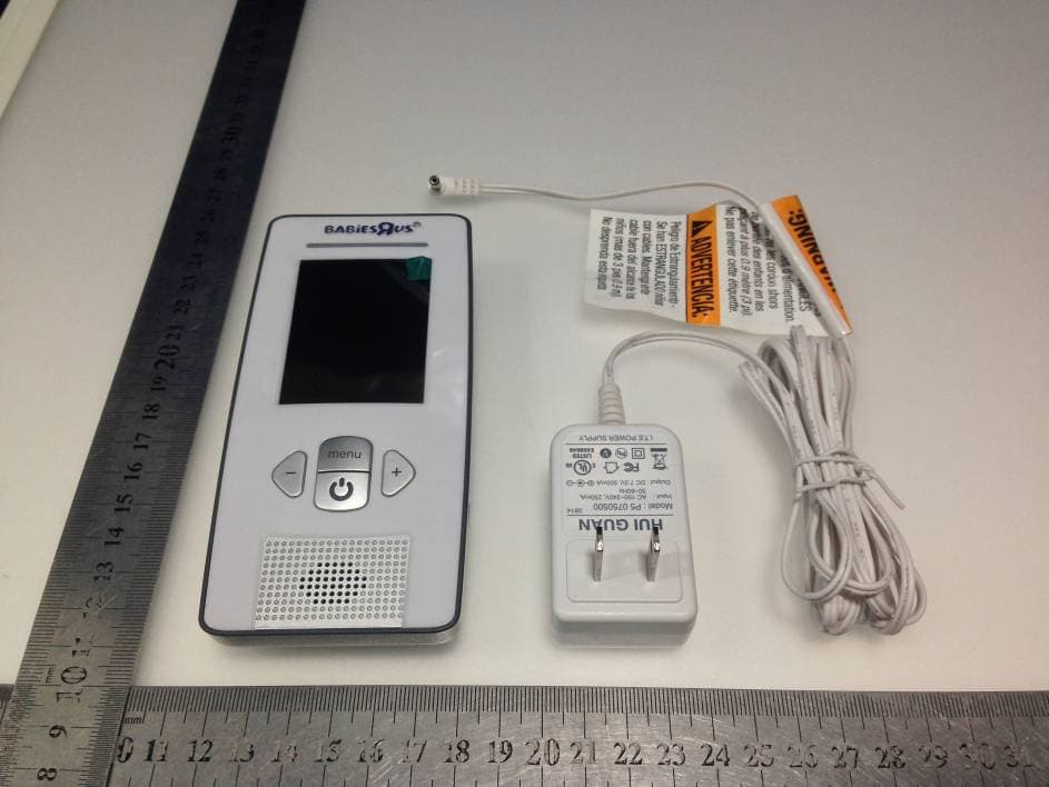
PJF-2146RX
Sep 28, 20142.4 inch color video monitor
Equipment Class
DSS - Part 15 Spread Spectrum Transmitter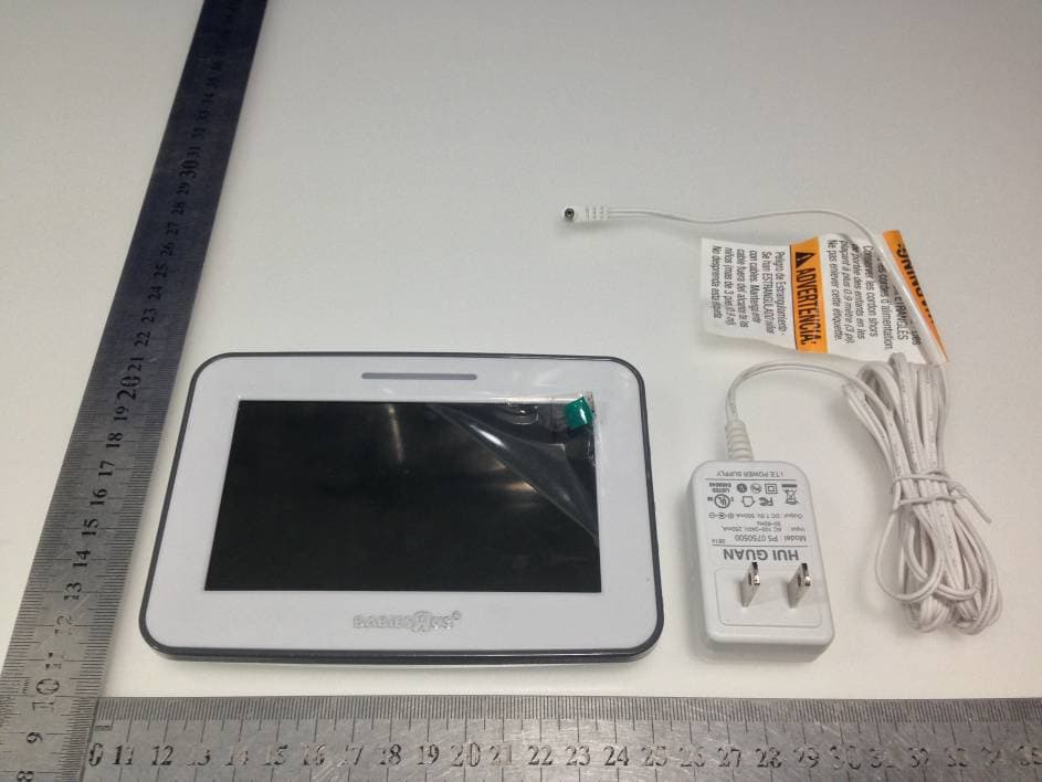
PJF-2313RX
Sep 25, 20145 inch color flatscreen video monitor
Equipment Class
DSS - Part 15 Spread Spectrum Transmitter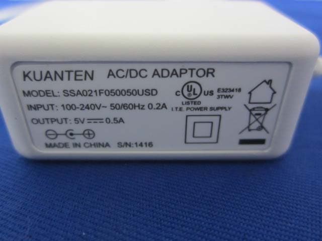
PJF-05000TX
Jun 22, 2014SMART TRAC Digital Audio Monitor
Equipment Class
DSS - Part 15 Spread Spectrum Transmitter