PJF-3927006RX15 inches Color Flatscreen Video Monitor
Baby's Journey, Inc.
Click to zoom
Application Details
- Equipment Class
- DSS - Part 15 Spread Spectrum Transmitter
- Date of Grant
- Dec 12, 2013
- Application Purpose
- Original Equipment
- Date of Application
- Dec 12, 2013
- Equipment Note
- 5 inches Color Flatscreen Video Monitor
- Frequency Range
- 2411.37500000 - 2472.12500000
- Company
- Baby's Journey, Inc.
- Country
- United States
Documents & Files
Document Text
Text extracted from the exhibit documents filed with the FCC. Open a document above to read the original.
Users Manual
Features & Components 5” Color Flatscreen Video Monitor User Guide5F62313 • Please read the following instructions and warnings carefully. • Keep these instructions for future reference. • Tool needed: Phillips Head Screwdriver (not included). • Additional camera(s) (sold separately). • For use with children from birth and up. Set-up and Use of Parent Unit (Monitor) 1 Remove protective cling from Parent Unit. Discard after you remove. 2 Connect AC adapter to the side of Parent Unit. 3 Plug Parent Unit into wall outlet to operate AC power. 4 To turn On, hold down Power On/Off button 3 seconds until Hello screen disappears. To turn Off, hold down Power On/Off Button 3 seconds until the Goodbye screen disappears. Important Safety Warnings CAUTION! KEEP SMALL PARTS OUT OF CHILD’S REACH. Sound Lights (5 LEDs) Power On Indicator 5 inch Video Screen Power On/Off & Menu Button AC Adapter Jack Volume +/- Buttons & Menu Up/Down Brightness +/- Buttons & Menu Left/Right Zoom Control Button & Enter Video On/Off Button Antenna Speaker Footrest Battery Compartment (for rechargeable battery) A B C D E F G H I J K L M Parent Unit (Monitor) Baby Unit (Camera) A B C NR T S U O P Q V D F G H E I J K LM Antenna Nighttime Viewing Lights Camera Lens Microphone Power On Indicator Pair Button Power On/Off Switch AC Adapter Jack Wall Mount Notch Room Darkening Automatic Sensor N O P Q R S T U V W AC Adapters (2) Security Clips (6) Wall AnchorScrew Set-up: Using your Parent Unit (Monitor): Plug in here Power On/Off Power On/Off Instructions continued on reverse side. * To order a new rechargeable battery pack, visit WWW.BABIESRUS.COM. WARNING! VOLUME CONTROL BUTTONS To adjust volume, press up (+) or down (-). Volume bar will display on screen. No bars means Parent Unit is on mute. BRIGHTNESS CONTROL BUTTONS To adjust the brightness, press up (+) or down (-). Brightness bar will display on screen. ZOOM CONTROL BUTTON To zoom in, press the Zoom Control Button. Zoom icon will display on screen. Press button again to return to normal viewing. Zoom icon will disappear from screen. VIDEO ON/OFF BUTTON Press the Video On/Off Button to shut-off the video screen. Press again to bring back full video. Please note that video will time out after approximately 2 minutes if on battery power. This function helps to conserve battery life*. LINK INDICATOR - OUT OF RANGE If the unit is working and goes out of range, the no-link icon appears on screen. Move units closer together to increase signal strength. Low signal is one bar and rises incrementally as the signal strength increases. DAY/NIGHT AUTO VIEWING Day/Night Auto Viewing lets you see your baby in a darkened room. For best view of your baby in a dark room, increase brightness control until desired brightness is achieved. For best visibility, Camera should be 3 feet away from your baby. BATTERY INDICATOR* When battery is fully charged, the green battery icon appears on screen with full bars. As the battery power lowers, the green bars start to go away. Low battery power is indicated when no bars appear, which the unit will power off. ANTENNA To increase signal strength, pull the antenna up. PLUG INDICATOR The plug icon indicates that the Parent Unit is connected to the AC adapter. Set-up and Use of Baby Unit (Camera) 1 Connect AC adapter to the back of Baby Unit (Camera). 2 Plug Baby Unit into wall outlet to operate AC power. 3 To turn On, slide Power On/Off switch to On and Power On Indicator will illuminate green. To turn Off, slide Power On/Off switch to Off. Set-up: Using your Baby Unit (Camera): DO NOT PLACE UNITS IN CRIB OR MOUNT ON CRIB. KEEP OUT OF REACH OF CHILDREN. Plug in here Strangulation Hazard - Children have STRANGLED in cords. Keep cords out of reach of children (more than 3 feet (0.9 m) away). WARNING! • Adult assembly is required. Keep small parts away from children. • This product is not a toy. Do not allow children to play with it. • This baby monitor is not a substitute for responsible adult supervision. • Do not place the baby monitor or cord in the crib. • Keep cords out of reach of children. • ALWAYS use enclosed Security Clips to help secure cord away from baby’s reach. • Never use extension cords with power adapters. Only use the power adapters provided. • Do not cover the baby monitor with a blanket or towel. • Test the baby monitor and all its functions so that you are familiar with it prior to actual use. • Do not use baby monitor near water. • Do not install the baby monitor near a heat source. • Only use the chargers and power adapters provided. Do not use other chargers or power adapters as this may damage the device and battery pack. • Only insert a battery pack of the same type. • When the power adapter is plugged into an electrical outlet, do not touch the exposed end. • Make sure there is proper ventilation around all baby monitor components. Do not place on soft surfaces. W IMPORTANT: When choosing locations to set up the Baby Unit (Camera) follow these guidelines: Table top Set Up: • Determine a location for the Baby Unit (Camera) that will provide the best view of your baby. Place the Baby Unit (Camera) on a flat surface, such as a dresser, bureau, or shelf (see diagram). NEVER place Baby Unit (Camera) or cords within 3 feet (0.9 m) of the baby's reach. ALWAYS secure the cord to the wall using the six (6) security clips included to keep cord away from baby's reach (see diagram). WARNING: Strangulation Hazard - Children have STRANGLED in cords. Keep cords out of reach of children (more than 3 feet (0.9 m) away). Wall Mounting: Mounting the Baby Unit (Camera) on a wall is similar to mounting a picture frame. Be sure to test reception and camera positioning before mounting to a wall. 1 Pre-drill a hole in the wall (3/16", 4.8mm, drill bit). 2 Insert the wall anchor into the hole and with a hammer, tap gently on the end until the wall anchor is flush with the wall. 3 Insert the screw into the wall anchor and tighten screw until only 1/4" (…
Text truncated - open the document above for the full version.
External Photos
EXHIBIT B - EUT EXTERNAL PHOTOGRAPHS EUT—All View EUT—Top View EUT—Bottom View EUT— Left Side View EUT— Right Side View EUT- Antenna View EUT- Adapter View EUT- Adapter Label View
Internal Photos
EXHIBIT B - EUT EXTERNAL PHOTOGRAPHS EUT- Battery Off View EUT- Battery Top View EUT- Battery Bottom View EUT- Uncover View EUT- Front Cover Off View EUT- LCD Display Top View EUT- LCD Display Bottom View EUT-Main Board Top with Shielding View EUT-Main Board Top without Shielding View EUT- Main Board Bottom View EUT- RF Chip View
Test Report
Note: This test report is prepared for the customer shown above and for the device described herein. It may not be duplicated or used in part without prior written consent from Bay Area Compliance Laboratories Corp. This report must not be used by the customer to claim product certification, approval, or endorsement by NVLAP*, or any agency of the Federal Government. * This report may contain data that are not covered by the NVLAP accreditation and shall be marked with an asterisk “★” (Rev.2). This report is valid only with a valid digital signature. The digital signature may be available only under the Adobe software above version 7.0. FCC PART 15.247 TEST REPORT For Baby’s Journey, Inc. 999 Main Street, Unit 703, Pawtucket, RI 02860, United States Report Type: Original Report Product Type: 5” Color Flatscreen Video Monitor Test En gineer: Leon Chen Re port Number: R2DG131111004-00A Re port Date: 2013-11-21 Reviewed By: Jerry Zhang EMC Manager Test Laboratory: Bay Area Compliance Laboratories Corp. (Dongguan) No.69 Pulongcun, Puxinhu Industrial Zone, Tangxia, Dongguan, Guangdong, China Tel: +86-769-86858888 Fax: +86-769-86858891 www.baclcorp.com.cn FCC ID: PJF-3927006RX1 Bay Area Compliance Laboratories Corp. (Dongguan) Report No.: R2DG131111004-00A FCC Part 15.247 Page 2 of 39 TABLE OF CONTENTS GENERAL INFORMATION ....................................................................................................................................... 4 PRODUCT DESCRIPTION FOR EQUIPMENT UNDER TEST (EUT) ..................................................................................... 4 OBJECTIVE ................................................................................................................................................................... 4 TEST METHODOLOGY .................................................................................................................................................. 4 TEST FACILITY ............................................................................................................................................................. 5 SYSTEM TEST CONFIGURATION .......................................................................................................................... 6 DESCRIPTION OF TEST CONFIGURATION ...................................................................................................................... 6 EUT EXERCISE SOFTWARE .......................................................................................................................................... 6 EQUIPMENT MODIFICATIONS ....................................................................................................................................... 6 SUPPORT EQUIPMENT LIST AND DETAILS .................................................................................................................... 6 EXTERNAL CABLE ........................................................................................................................................................ 6 BLOCK DIAGRAM OF TEST SETUP ................................................................................................................................ 7 SUMMARY OF TEST RESULTS ............................................................................................................................... 8 FCC §15.247 (i) & §1.1310 & §2.1091- MAXIMUM PERMISSIBLE EXPOSURE (MPE) ......................................... 9 APPLICABLE STANDARD .............................................................................................................................................. 9 FCC §15.203 - ANTENNA REQUIREMENT ........................................................................................................... 10 APPLICABLE STANDARD ............................................................................................................................................ 10 ANTENNA CONNECTOR CONSTRUCTION .................................................................................................................... 10 FCC §15.207 (a) – AC LINE CONDUCTED EMISSIONS ..................................................................................... 11 APPLICABLE STANDARD ............................................................................................................................................ 11 MEASUREMENT UNCERTAINTY .................................................................................................................................. 11 EUT SETUP ................................................................................................................................................................ 11 EMI TEST RECEIVER SETUP ....................................................................................................................................... 12 TEST PROCEDURE ...................................................................................................................................................... 12 CORRECTED AMPLITUDE & MARGIN CALCULATION ................................................................................................. 12 TEST EQUIPMENT LIST AND DETAILS ......................................................................................................................... 13 TEST RESULTS SUMMARY .......................................................................................................................................... 13 TEST DATA ................................................................................................................................................................ 13 FCC §15.209, §15.205 & §15.247(d) - SPURIOUS EMISSIONS ............................................................................. 16 APPLICABLE STANDARD .........................................................................................................…
Text truncated - open the document above for the full version.
Test Setup Photos
EXHIBIT D - TEST SETUP PHOTOGRAPHS Conducted Emissions - Front View Conducted Emissions – Side View Radiated Emission -Front View (Below 1GHz) Radiated Emission - Rear View (Below 1GHz) Radiated Emission -Front View (Above 1GHz) Radiated Emission - Rear View (Above 1GHz)
Contact Information
Applicant
Steve Gibree(President)
Test Firm
Bay Area Compliance Laboratories Corp. (Dongguan)John Chan
[email protected]86-769-86858888
Technical Specifications
| # | Rule Parts | Frequency Range | Power Output |
|---|---|---|---|
| 1 | 15C | 2.41 GHz - 2.47 GHz | 7.00 mW |
Other Applications from Baby's Journey, Inc.
PJF-05010RX
Jan 27, 2015SMART SYNC 5 inches Internet Viewable Touch Screen Video Monitor
Equipment Class
DTS - Digital Transmission System
PJF-05020RX
Jan 27, 2015SMART LINK 4.3 inches Touch Screen Video Monitor
Equipment Class
DTS - Digital Transmission System
PJF-2146RX
Sep 28, 20142.4 inch color video monitor
Equipment Class
DSS - Part 15 Spread Spectrum Transmitter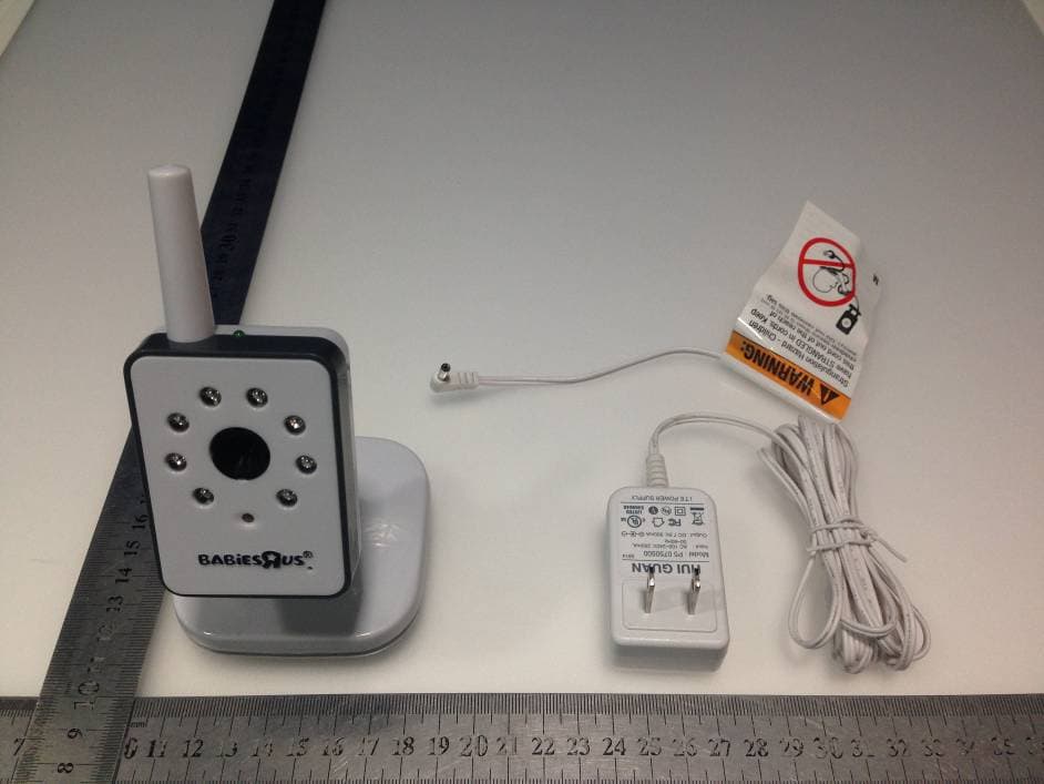
PJF-2313TX
Sep 28, 20145 inch color flatscreen video monitor
Equipment Class
DSS - Part 15 Spread Spectrum Transmitter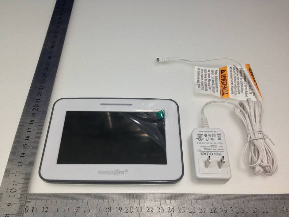
PJF-2313RX
Sep 25, 20145 inch color flatscreen video monitor
Equipment Class
DSS - Part 15 Spread Spectrum Transmitter