PKXTW63-PWHO'S FIRST-TOUCH PAD
Trainers Warehouse
Click to zoom
Application Details
- Equipment Class
- DXX - Part 15 Low Power Communication Device Transmitter
- Date of Grant
- Mar 28, 2010
- Application Purpose
- Original Equipment
- Date of Application
- Mar 28, 2010
- Equipment Note
- WHO'S FIRST-TOUCH PAD
- Frequency Range
- 915.00000000 - 915.00000000
- Company
- Trainers Warehouse
- Country
- United States
Documents & Files
Document Text
Text extracted from the exhibit documents filed with the FCC. Open a document above to read the original.
Users Manual
Who’s First? You Are. Congratulations on your new purchase of Who’s First.™. Wireless? We’re sure this buzzer system will be the key to unlocking your group’s energy, generating excitement and adding “game show-like” spirit to your question and answer activities. Using this system, you will surely be ahead of the market. In addition to your students’ having fun, they will be really impressed with your sexy new technology. Wireless This new wireless option works just like our well established Who’s First™. It is a brand new version and works without the encumbrance of interconnecting wires. However because of the new technology, there are some precautions that should be observed. The dynamic range of operation is from 3 feet to 60 feet. The transmitter buttons when pressed will not work at less than 3 feet or more than 60 feet. Each switch/transmitter is furnished with a battery and that battery should last for tens of thousands of depressions. Fresh batteries are easy to obtain, either from The Trainers Warehouse or from popular battery vendors like Radio Shack. The identification number for the battery is_______. Each switch/transmitter furnished to you has been tested for hundreds of transmissions before being sent to you. There should be no problems with the operation of the unit during your games. In the event of any problems or questions, you should contact the factory at 800-299-3770 Trouble Shooting Before starting your game with the participating teams, it is a good idea to have each group press there button to be sure that the signal is being detected by the signal box. If no detection or spurious light signals are noted on the control box, confirm that the button is being pressed within the dynamic range of 3 to 60 feet. The range of Who’s First Wireless is adversely affected when the detector is situated on a metal table and shielded by Metal walls. Try the unit without being positioned on a metal wall. If spurious results are occurring, be sure that there is no strong radio signal in the area. With spurious results, the unit can be reset by turning the master control off and then on. Maintenance The only maintenance that might be required is replacement of the battery. This should not be required more than once per year with normal use. To replace the battery you must first obtain a battery. Radio Shack has the batteries in stock and if there should be a problem obtaining it from them, just call us and we can send you a replacement at the replacement cost. To position the new battery, just spread apart the walls of the black switch box on the two sides where the metal screws can be seen. The circuit board with the battery on the top side is immediately apparent. Pull the battery out and replace it with the replacement battery. Or if time permits, you are welcome to send it back to us and we will replace the battery for you. Any other problems, you are always welcome to call us. 1-(800)-299-3770. We appreciate your comments. We would appreciate knowing how this product is working for you. As you can tell, we’re excited about Who’s First™; and, although we’ve already invested lots in its development, we do want to make it truly perfect. So, please do call or write with comments, suggestions, or questions . Good Luck and have fun! THE MANUFACTURER IS NOT RESPONSIBLE FOR ANY RADIO OR TV INTERFERENCE CAUSED BY UNAUTHORIZED MODIFICATIONS TO THIS EQUIPMENT. SUCH MODIFICATIONS COULD VOID THE USER'S AUTHORITY TO OPERATE THE EQUIPMENT. IMPORTANT SET-UP INSTRUCTIONS! PLEASE READ SET-UP CAREFULLY! 2 1 Set-up Red, Yellow, Green, Blue The touch boxes are sent to you pre-attached. However, if you must reconnect the unit, It’s really important that the touch boxes are connected to the main module in the correct order. Notice the touch box labels specify “Connect this side to x color.” Please make certain you connect the indicated side of the box to the next unit. If you connect the wrong side of the touch box to the following box, you will cause the wrong lamp to light. Using the 16 foot telephone-like cords connect the main module first to the red side of the red touch pad, then connect the yellow side of the red box to the yellow touch box. Accordingly, connect the green, then the blue. On the Main Module box, be sure to plug touch pads into the single upper phone jack, labeled “Touch Pads.” DO NOT plug Touch Boxes into the jack labeled “Extension Modules.” The main module can either lay flat or stand up on end. Rest each of the four Touch Boxes on a flat surface. As the touch sensors are located in the feet of the boxes, they will not work properly as hand-held devices. Power Source Now, plug the unit into any power source. There is no on/off switch. Once plugged in, the unit is ready to go. Multiple Modules Each Who’s First™ can be used as either a stand-alone units or as an integrated set. Any one of the units can be plugged into the power source for all to be operable. Once connected, the reset buttons are interchangeable. If you wish to expand Who’s First™ to accommodate additional teams, simply connect two or more of the Main Modules together. To do this, plug the short Connector cord into either of the jacks labeled “Extension Modules.” When using the Who’s First™ for more than four teams, we recommend numbering each set so that there is no confusion about which yellow team or which red team rang in first. Using Who’s First Who is First? The FIRST team to ring in will see their corresponding LIGHT turn on and stay lit (no blinking). The SECOND team to ring in will see their corresponding light blink. The Red Reset Button You will notice a red “Reset” button. The Reset serves two functions: 1) it turns off the four colored lights; 2) it allows you to control when the contest to “ring in” can begin. When you have finished asking your question and are ready for teams to “ring in,” release the button. The Buzzer We made the buzzer really loud so that it could be heard from the back of t…
Text truncated - open the document above for the full version.
Cover Letter(s)
Trainer’s Warehouse 89 Washington Avenue Natick, MA 01760-3441 P - (800)299-3770 F –(508)651-2674 01/21/2010 Federal Communications Commission Authorization and Evaluation Division Confidentiality Request regarding application for certification of FCC ID: PKXTW63-P Pursuant to Sections 0.457 and 0.459 of the Commission’s Rules, we hereby request confidential treatment of information accompanying this application as outlined below: Exhibit Type File Name Block Diagram Block diagram.pdf Schematics Schematics.pdf Operational Description SG338 Slave Unit Operation Description.pdf Parts List SG338, Slave Unit, BOM.pdf The above materials contain trade secrets and proprietary information not customarily released to the public. The public disclosure of these materials may be harmful to the applicant and provide unjustified benefits to its competitors. Sincerely, Mike Doctoroff Trainers Warehouse
External Photos
APPLICANT: TRAINER’S WAREHOUSE FCC ID: PKXTW63-P EXTERNAL PHOTOS
ID Label/Location Info
CR2016 3V CR2016 3V FCC ID:PKXTW63-P THIS DEVICE COMPLIES WITH PART 15 OF THE FCC RULES. OPERATION IS SUBJECT TO THE FOLLOWING TWO CONDITIONS: (1) THIS DEVICE MAY NOT CAUSE HARMFUL INTERFERENCE AND (2) THIS DEVICE MUST ACCEPT ANY INTERFERENCE RECEIVED, INCLUDING INTERFERENCE THAT MAY CAUSE UNDESIRED OPERATION. © 2010 Trainer’s Warehouse www.trainerswarehouse.com 1-800-299-3770 Product Code: WHOR6W Made in China FCC ID:PKXTW63 THIS DEVICE COMPLIES WITH PART 15 OF THE FCC RULES. OPERATION IS SUBJECT TO THE FOLLOWING TWO CONDITIONS: (1) THIS DEVICE MAY NOT CAUSE HARMFUL INTERFERENCE AND (2) THIS DEVICE MUST ACCEPT ANY INTERFERENCE RECEIVED, INCLUDING INTERFERENCE THAT MAY CAUSE UNDESIRED OPERATION.
Internal Photos
APPLICANT: TRAINER’S WAREHOUSE FCC ID: PKXTW63-P INTERNAL PHOTOS
Test Report
FCC PART 15.249 TEST REPORT UNLICENSED INTENTIONAL RADIATOR Applicant TRAINERS WAREHOUSE Address 89 WASHINGTON AVENUE NATICK MASSACHUSETTS 01760 USA FCC ID PKXTW63-P Product Description WHO’S FIRST – TOUCH PAD Date Sample Received 1/21/2010 Date Tested 1/25/2010 Tested By Richard Block Approved By Mario de Aranzeta Report Number 147UT10TestReport.doc Test Results PASS FAIL THE ATTACHED REPORT SHALL NOT BE REPRODUCED EXCEPT IN FULL WITHOUT THE WRITTEN APPROVAL OF TIMCO ENGINEERING, INC. 849 NW State Road 45 Newberry, FL 32669 USA Ph: 888.472.2424 or 352.472.5500 Fax: 352.472.2030 Email: [email protected] Website: www.timcoengr.com Certificate # 0955-01 APPLICANT: TRAINERS WAREHOUSE FCC ID: PKXTW63-P REPORT #: Z:\T\TRAINERS\147UT10\147UT10TestReport.doc Page 2 of 13 Mdea 9.20.2007 TABLE OF CONTENT GENERAL REMARKS....................................................................................................................... 3 GENERAL INFORMATION ................................................................................................................ 4 EMC EQUIPMENT LIST ................................................................................................................... 5 TEST PROCEDURES ....................................................................................................................... 6 RADIATION INTERFERENCE ........................................................................................................... 7 OCCUPIED BANDWIDTH ................................................................................................................. 9 BAND EDGE COMPLIANCE ........................................................................................................... 10 DUTY CYCLE ................................................................................................................................ 12 RADIATED EMISSIONS TEST SETUP PHOTO ................................................................................ 13 APPLICANT: TRAINERS WAREHOUSE FCC ID: PKXTW63-P REPORT #: Z:\T\TRAINERS\147UT10\147UT10TestReport.doc Page 3 of 13 Mdea 9.20.2007 GENERAL REMARKS The attached report shall not be reproduced except in full without the written permission of Timco Engineering Inc. Summary The device under test does: fulfill the general approval requirements as identified in this test report not fulfill the general approval requirements as identified in this test report Attestations This equipment has been tested in accordance with the standards identified in this test report. To the best of my knowledge and belief, these tests were performed using the measurement procedures described in this report. All instrumentation and accessories used to test products for compliance to the indicated standards are calibrated regularly in accordance with ISO 17025 requirements. Certificate # 0955-01 I attest that the necessary measurements were made, under my supervision, at: Timco Engineering Inc. 849 NW State Road 45 Newberry, Fl 32669 Authorized Signatory Name: Mario de Aranzeta C.E.T. Compliance Engineer/ Lab. Supervisor Date: 1/25/10 APPLICANT: TRAINERS WAREHOUSE FCC ID: PKXTW63-P REPORT #: Z:\T\TRAINERS\147UT10\147UT10TestReport.doc Page 4 of 13 Mdea 9.20.2007 GENERAL INFORMATION DUT Specification The test results relate only to the items tested. Applicable Standard Part 15.249 DUT Description WHO’S FIRST – TOUCH PAD FCC ID PKXTW63-P Operating Frequency TX: 916 MHz RX: Same DUT Power Source 110–120Vac/50– 60Hz DC Power Battery Operated Exclusively Test Item Prototype Pre-Production Production Type of Equipment Fixed Mobile Portable Antenna Connector FCC Rules require that the antenna connector be unique. Test Facility Timco Engineering Inc. located at 849 NW State Road 45 Newberry, FL 32669 USA. Test Conditions Temperature: 26ºC Relative humidity: 50% Test Exercise The DUT was placed in continuous transmit mode of operation. Test Supporting Equipment Supporting Device Manufacturer Model / FCC ID Serial Number N/A APPLICANT: TRAINERS WAREHOUSE FCC ID: PKXTW63-P REPORT #: Z:\T\TRAINERS\147UT10\147UT10TestReport.doc Page 5 of 13 Mdea 9.20.2007 EMC EQUIPMENT LIST Device Manufacturer Model Serial Number Cal/Char Date Due Date 3-Meter Semi- Anechoic Chamber Panashield N/A N/A Listed 5/11/07 5/11/10 AC Voltmeter HP 400FL 2213A14499 CAL 3/23/09 3/23/10 Analyzer Tan Tower Quasi-Peak Adapter HP 85650A 3303A01690 CAL 11/22/09 11/22/11 Analyzer Tan Tower RF Preselector HP 85685A 3221A01400 CAL 11/21/09 11/21/11 Analyzer Tan Tower Spectrum Analyzer HP 8566B Opt 462 3138A07786 3144A20661 CAL 11/24/09 11/24/11 Analyzer Tan Tower Preamplifier HP 8449B-H02 3008A00372 CAL 11/21/09 11/21/11 Coaxial Cable #64 Semflex Inc. 60637 Timco #64 CHAR 3/30/09 3/30/11 Antenna: Dipole Kit Electro-Metrics TDA-30/1- 4 152 CAL 3/3/09 3/3/12 Antenna: Dipole Kit Electro-Metrics TDA-30/1- 4 153 CHAR 4/5/09 4/5/12 Hygro- Thermometer Extech 445703 0602 CAL 1/30/09 1/30/11 Modulation Analyzer HP 8901A 3435A06868 CAL 5/9/09 5/9/11 Digital Multimeter Fluke FLUKE-77- 3 79510405 CAL 5/14/09 5/14/11 System One Audio Precision System One SYS1-45868 CHAR 2/27/08 2/27/10 Temperature Chamber Tenney Engineering TTRC 11717-7 CHAR 4/25/08 4/25/10 APPLICANT: TRAINERS WAREHOUSE FCC ID: PKXTW63-P REPORT #: Z:\T\TRAINERS\147UT10\147UT10TestReport.doc Page 6 of 13 Mdea 9.20.2007 TEST PROCEDURES Radiation Interference: ANSI C63.4-2003 using a spectrum analyzer, a preselector, a quasi- peak adapter, and an appropriate antenna. The analyzer was calibrated in dB above a microvolt at the output of the antenna. The resolution bandwidth was 100 kHz with an appropriate sweep speed and the video bandwidth was 300 kHz up to 1 GHz and 1 MHz with a video BW of 3 MHz above 1 GHz. When an emission was found, the table was rotated to produce the maximum signal strength. The antenna was placed in both the horizontal and vertical planes and the worse case emissions were reported. The spectrum was searched to …
Text truncated - open the document above for the full version.
Contact Information
Applicant
SUSAN LANDAY
Test Firm
Timco Engineering, Inc.Bruno Clavier
Technical Specifications
| # | Rule Parts | Frequency Range | Power Output |
|---|---|---|---|
| 1 | 15C | 915 MHz - 915 MHz | - |
Other Applications from Trainers Warehouse
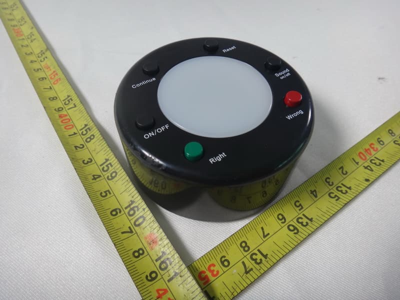
PKX1301GAMFX
Nov 08, 2012Personal Answer Pad
Equipment Class
DSS - Part 15 Spread Spectrum Transmitter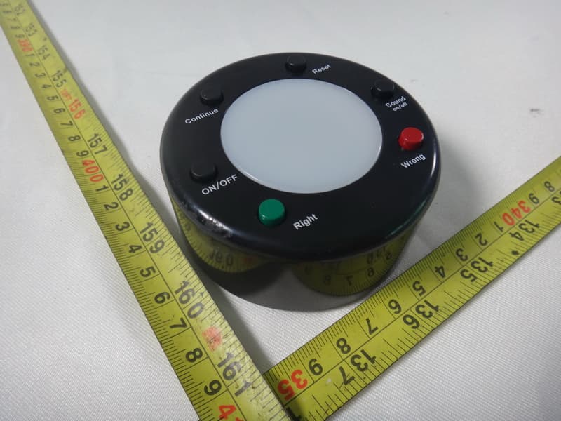
PKX1301GAMFZ
Nov 08, 2012Facilitator Control Unit
Equipment Class
DSS - Part 15 Spread Spectrum Transmitter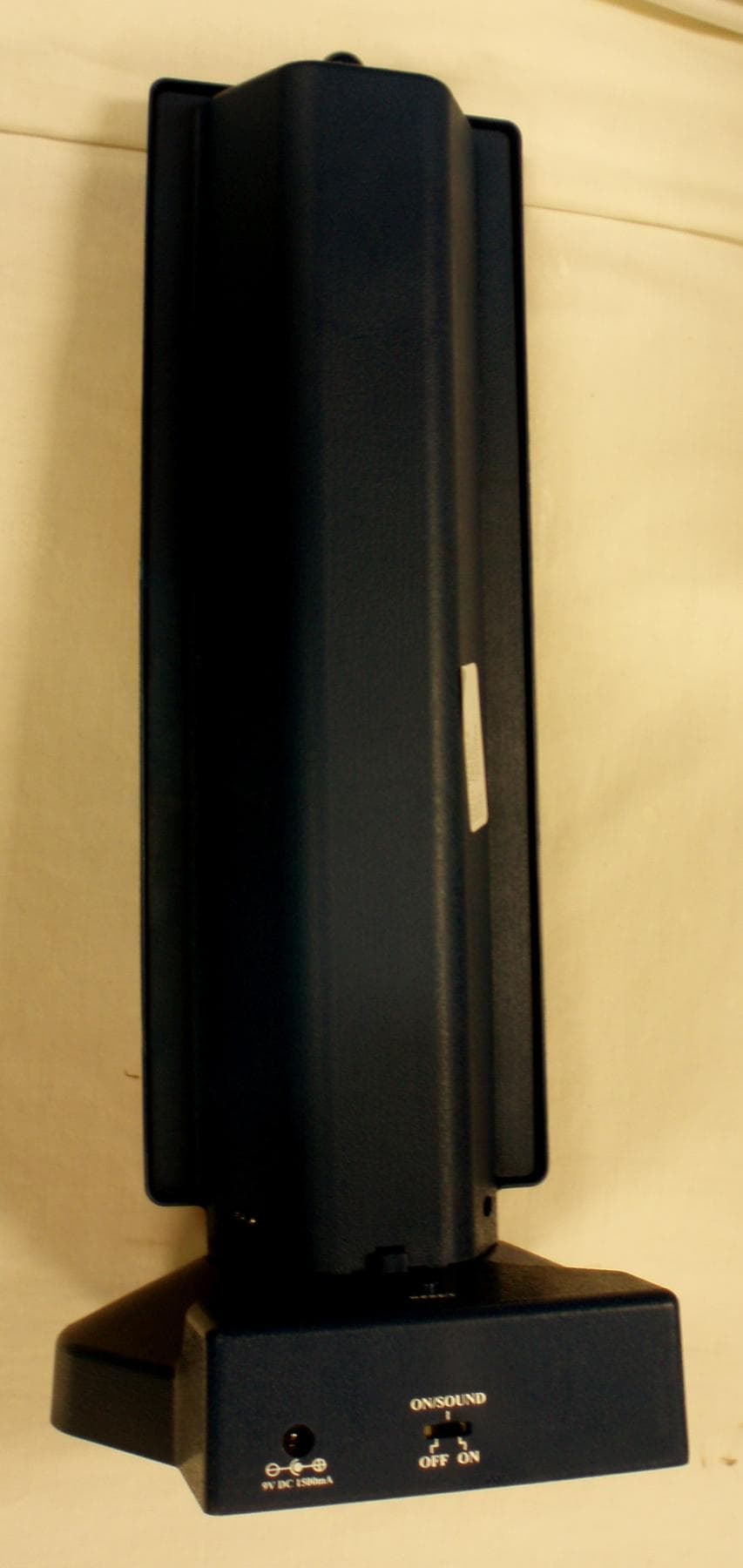
PKXTW63
Mar 28, 2010WHO'S FIRST-TOWER
Equipment Class
DXX - Part 15 Low Power Communication Device Transmitter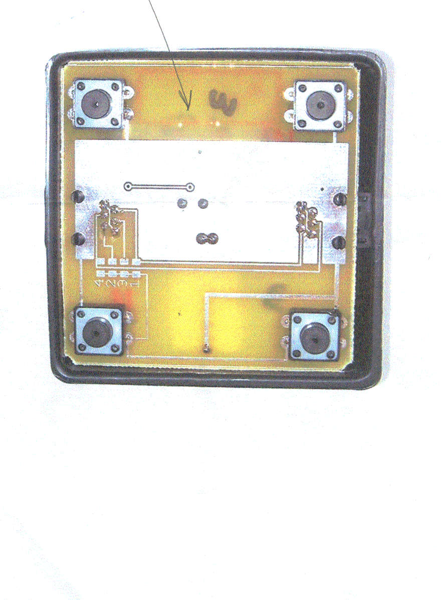
PKXWT2000
Jun 06, 2001315 MHz Transmitter
Equipment Class
DSC - Part 15 Security/Remote Control Transmitter