PKXWT2000315 MHz Transmitter
Trainers Warehouse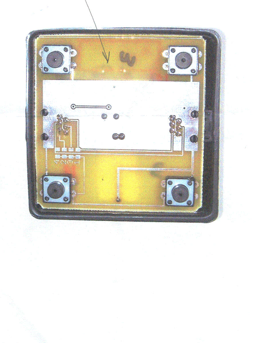
Click to zoom
Application Details
- Equipment Class
- DSC - Part 15 Security/Remote Control Transmitter
- Date of Grant
- Jun 06, 2001
- Application Purpose
- Original Equipment
- Date of Application
- Jun 06, 2001
- Equipment Note
- 315 MHz Transmitter
- Frequency Range
- 314.50000000 - 317.00000000
- Company
- Trainers Warehouse
- Country
- United States
Documents & Files
Document Text
Text extracted from the exhibit documents filed with the FCC. Open a document above to read the original.
Users Manual
For WHOFIW-Model 2000-1 Who’s First? You Are. Congratulations on your new purchase of Who’s First.™. Wireless? We’re sure this buzzer system will be the key to unlocking your group’s energy, generating excitement and adding “game show-like” spirit to your question and answer activities. Using this system, you will surely be ahead of the market. In addition to your students’ having fun, they will be really impressed with your sexy new technology. Wireless This new wireless option works just like our well established Who’s First™... It is a brand new version and works without the encumbrance of interconnecting wires. However because of the new technology, there are some precautions that should be observed. There are 5 touch boxes for the wireless version. The colors on 4 match the colors of the lights on the receiver. The 5th touch box is used by the person controlling the game and will reset the receiver at any time. It works the same as momentarily pressing the red reset button on the receiver. However, it cannot be pressed continuously to control the start of the game. It is also possibler to use the red reset button on the receiver instead of the wireless reset box. The dynamic range of operation is from 3 feet to 60 feet. The transmitter buttons when pressed will not work at less than 3 feet or more than 60 feet. Each switch/transmitter is furnished with a battery and that battery should last for tens of thousands of depressions. Fresh batteries are easy to obtain, either from The Trainers Warehouse or from popular battery vendors like Radio Shack. The identification number for the battery is CR2032. Each switch/transmitter furnished to you has been tested for hundreds of transmissions before being sent to you. There should be no problems with the operation of the unit during your games. In the event of any problems or questions, you should contact the factory at 800-299-3770 • • Trouble Shooting Before starting your game with the participating teams, it is a good idea to have each group press there button to be sure that the signal is being detected by the signal box. If no detection or spurious light signals are noted on the control box, confirm that the button is being pressed within the dynamic range of 3 to 60 feet. The range of Who’s First Wireless is adversely affected when the transmitters and possibly the receiver is situated on a metal table and shielded by Metal walls. Try the unit without being positioned on a metal wall. If spurious results are occurring, be sure that there is no strong radio signal in the area. With spurious results, the unit can be reset by pushing the red reset button on top of the receiver. Maintenance The only maintenance that might be required is replacement of the battery. This should not be required more than once per year with normal use. To replace the battery you must first obtain a battery. Radio Shack has the batteries in stock and if there should be a problem obtaining it from them, just call us and we can send you a replacement at the replacement cost. To position the new battery, just spread apart the walls of the black switch box on the two sides where the metal screws can be seen. The circuit board with the battery on the top side is immediately apparent. Press the round button near the center of the battery on the battery holder, and the battery will pop out. A small arrow on the side of the battery holder closest to the center of the board points to the button. The new battery is inserted with the + side up by pressing on the outside edge of the battery indicated by a small arrow on the outside edge of the battery holder. If time permits, you are welcome to send it back to us and we will replace the battery for you. Any other problems, you are always welcome to call us. 1-(800)-299-3770. We appreciate your comments. We would appreciate knowing how this product is working for you. As you can tell, we’re excited about Who’s First™; and, although we’ve already invested lots in its development, we do want to make it truly perfect. So, please do call or write with comments, suggestions, or questions . Good Luck and have fun! • Wired Operation This unit may be used with wires if it is desired. The circuitry is in place for wired operation but one precaution must be observed-To use this unit with wires, the batteries must be removed from each of the hand operated transmitter devices. Please call the factory if you desire to do this and the proper wires will be sent to you. Set-up Red, Yellow, Green, Blue It’s really important that the touch boxes are connected to the main module in the correct order. Notice the touch box labels specify “Connect this side to x color.” Please make certain you connect the indicated side of the box to the next unit. If you connect the wrong side of the touch box to the following box, you will cause the wrong lamp to light.. Using the 16 foot telephone- like cords connect the main module first to the red side of the red touch pad, then connect the yellow side of the red box to the yellow touch box. Accordingly, connect the green, then the blue. On the Main Module box, be sure to plug touch pads into the single upper phone jack, labeled “Touch Pads.” DO NOT plug Touch Boxes into the jack labeled “Extension Modules.” The main module can either lay flat or stand up on end. Rest each of the four Touch Boxes on a flat surface. As the touch sensors are located in the feet of the boxes, they will not work properly as hand-held devices. Power Source Now, plug the unit into any power source. There is no on/off switch. Once plugged in, the unit is ready to go. Multiple Modules Each Who’s First™ can be used as either a stand-alone units or as an integrated set. Any one of the units can be plugged into the power source for all to be operable. Once connected, the reset buttons are interchangeable. If you wish to expand Who’s First™ to accommodate additional teams, simply connect two or more of the Main Modules together. To do …
Text truncated - open the document above for the full version.
ID Label/Location Info
TRAINERS WAREHOUSE LABEL SAMPLE PKXWT2000 TRAINERS WAREHOUSE FCC ID : PKXWT200 JOB # : 155ZU1 EXHIBIT # : 4
Operational Description
Trainer's Warehouse Transmitter Description The TH7107 transmitter IC, IC1, contains an internal oscillator phase locked loop which locks the oscillator to 32 times the external crystal frequency. Therefore a crystal frequency of 9.844Mhz produces an output frequency of 315.0MHz. The PLL loop filter components are C6, R1, C5. The frequency is FSK modulated by switching C2 in parallel with C1 with an internal transistor which is driven by the input to pin3. The frequency shift results in approximately a 50KHz output frequency shift. The output of IC1 is a balanced open collector so L1 and L2 provide the collector voltage, and C7, C8 form a tuned loop. CT1 is not used because C7 is selected for correct loop tuning. The output power can be adjusted by changing R3 sets current in the output stage. Q1,Q2,C10,R5,R9,R6,R11,C14 form a triggered monostable multivibrator which turns the transmitter on for approximately 180mS when one or more of the switches, SW1 through SW4, are pressed. In oder to reduce the effect of spurious signals, a tone of approximately 4.8KHz is transmitted. This is obtained by dividing the crystal frequency by 2048. IC1 contains an internal divider which produces ¼ the crystal frequency at pin 8. U1 is a CMOS divider which is used to divide the signal on pin 8 of IC1 by 512. The 4.8KHz signal on pin 13 of U1 is applied to the FSK input, pin 3 of IC1. TRAINERS WAREHOUSE FCC ID : PKXWT2000 JOB # : 155ZU1 EXHIBIT # : 10
Test Report
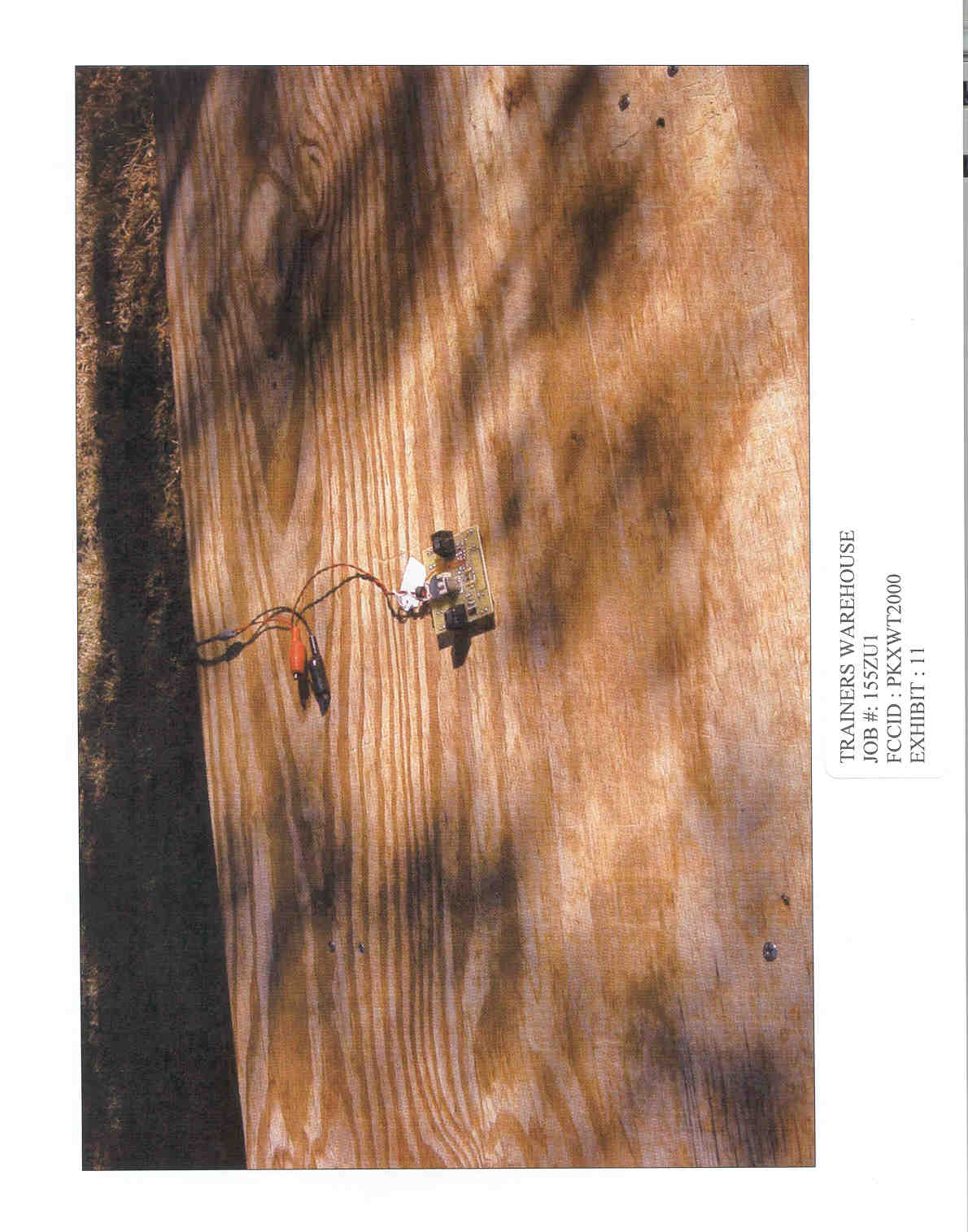
TABLE OF CONTENTS APPLICANT: TRAINERS WAREHOUSE FCC ID: PKXWT2000 TEST REPORT CONTAINING: PAGE 1.............TEST EQUIPMENT LIST & TEST PROCEDURE PAGE 2.............TEST PROCEDURE CONTD. PAGE 3.............RADIATION INTERFERENCE TEST DATA PAGE 4.............OCCUPIED BANDWIDTH TEST DATA PAGE 5.............OCCUPIED BANDWIDTH PLOT EXHIBIT ATTACHMENTS: EXHIBIT 1...........BLOCK DIAGRAM EXHIBIT 2...........SCHEMATIC EXHIBIT 3A-3E.......INSTRUCTION MANUAL EXHIBIT 4...........FCC ID LABEL SAMPLE EXHIBIT 5...........SKETCH OF FCC ID LABEL LOCATION EXHIBIT 6...........TOP VIEW EXTERNAL PHOTO EXHIBIT 7...........BOTTOM VIEW EXTERNAL PHOTO EXHIBIT 8...........COMPONENT SIDE INTERNAL PHOTO EXHIBIT 9...........COPPER SIDE INTERNAL PHOTO EXHIBIT 10..........CIRCUIT DESCRIPTION EXHIBIT 11..........TEST SET UP PHOTO APPLICANT: TRAINERS WAREHOUSE FCC ID: PKXWT2000 REPORT #: T\TRAINERS\155ZU1\155ZU1RPT.doc PAGE: TABLE OF CONTENTS LIST APPLICANT: TRAINERS WAREHOUSE FCC ID: PKXWT2000 TEST EQUIPMENT LIST 1._X_Spectrum Analyzer: HP 8566B-Opt 462, S/N 3138A07786, w/ preselector HP 85685A, S/N 3221A01400, Quasi-Peak Adapter HP 8565OA, S/N 3303A01690 & Preamplifier HP 8449B-OPT H02, S/N 3008A00372 Cal. 10/17/99 2._X_Biconnical Antenna: Eaton Model 94455-1, S/N 1057 3.___Biconnical Antenna: Electro-Metrics Model BIA-25, S/N 1171 4._X_Log-Periodic Antenna: Electro-Metrics Model EM-6950, S/N 632 5.___Log-Periodic Antenna: Electro-Metrics Model LPA-30, S/N 409 6._X_Double-Ridged Horn Antenna: Electro-Metrics Model RGA-180, 1-18 GHz, S/N 2319 7.___18-26.3GHz Systron Donner Standard Gain Horn #DBE-520-20 8.___Horn 40-60GHz: ATM Part #19-443-6R 9.___Line Impedance Stabilization Network: Electro-Metrics Model ANS-25/2, S/N 2604 Cal. 2/9/00 10.___Temperature Chamber: Tenney Engineering Model TTRC, S/N 11717-7 11.___Frequency Counter: HP Model 5385A, S/N 3242A07460 Cal 10/6/99 12.___Peak Power Meter: HP Model 8900C, S/N 2131A00545 13._X_Open Area Test Site #1-3meters Cal. 12/22/99 14.___Signal Generator: HP 8640B, S/N 2308A21464 Cal. 9/23/99 15.___Signal Generator: HP 8614A, S/N 2015A07428 16.___Passive Loop Antenna: EMCO Model 6512, 9KHz to 30MHz, S/N 9706-1211 Cal. 6/10/00 17.___Dipole Antenna Kit: Electro-Metrics Model TDA-30/1-4, S/N 153 Cal. 11/24/99 18.___AC Voltmeter: HP Model 400FL, S/N 2213A14499 Cal. 9/21/99 19.___Digital Multimeter: Fluke Model 8012A, S/N 4810047 Cal 9/21/99 20.___Digital Multimeter: Fluke Model 77, S/N 43850817 Cal 9/21/99 21.___Oscilloscope: Tektronix Model 2230, S/N 300572 Cal 9/23/99 TEST PROCEDURE GENERAL: This report shall NOT be reproduced except in full without the written approval of TIMCO ENGINEERING, INC. RADIATION INTERFERENCE: The test procedure used was ANSI STANDARD C63.4-1992 using a HEWLETT PACKARD spectrum analyzer with a prese- lector. The bandwidth of the spectrum analyzer was 100 kHz with an appropriate sweep speed. The analyzer was calibrated in dB above a microvolt at the output of the antenna. The resolution bandwidth was 100KHz and the video bandwidth was 300KHz. The ambient temperature of the UUT was 72ºF with a humidity of 21%. REPORT #: T\TRAINERS\155ZU1\155ZU1RPT.doc PAGE #: 1 TEST PROCEDURES CONTD. FORMULA OF CONVERSION FACTORS: The Field Strength at 3m was estab- lished by adding the meter reading of the spectrum analyzer (which is set to read in units of dBuV) to the antenna correction factor sup- plied by the antenna manufacturer. The antenna correction factors are stated in terms of dB. The gain of the Preselector was accounted for in the Spectrum Analyzer Meter Reading. Example: Freq (MHz) METER READING + ACF = FS 33 20 dBuV + 10.36 dB = 30.36 dBuV/m @ 3m ANSI STANDARD C63.4-1992 10.1.7 MEASUREMENT PROCEDURES: The UUT was placed on a table 80 cm high and with dimensions of 1m by 1.5m. The UUT was placed in the center of the table. The table used for radiat- ed measurements is capable of continuous rotation. The spectrum was scanned from 30 MHz to 10th harmonic of the fundamental. Peak readings were taken in three (3) orthogonal planes and the high- est readings were converted to average readings based on the duration of "ON" time. Measurements were made by TIMCO ENGINEERING INC. at the registered open field test site located at 849 N.W. State Road 45, Newberry, Fl 32669. When an emission was found, the table was rotated to produce the maximum signal strength. At this point, the antenna was raised and lowered from 1m to 4m. The antenna was placed in both the horizontal and vertical planes. ANTENNA & GROUND: This unit uses the PCB inductor as the antenna. There is no provision for an external antenna. APPLICANT: TRAINERS WAREHOUSE FCC ID: PKXWT2000 REPORT #: T\TRAINERS\155ZU1\155ZU1RPT.doc PAGE #: 2 APPLICANT: TRAINERS WAREHOUSE FCC ID: PKXWT2000 NAME OF TEST: RADIATION INTERFERENCE RULES PART NO.: 15.231 REQUIREMENTS: Fundamental Field Strength Field Strength of Frequency of Fundamental Harmonics and Spurious MHz dBuV Emissions (dBuV/m @ 3m) 40.66 to 40.70 67.04 47.04 70 to 130 61.94 41.94 130 to 174 61.94 to 71.48 41.94 to 51.48 174 to 260 71.48 51.48 260 to 470 71.48 to 81.94 51.48 to 61.94 470 and above 81.94 61.94 THE LIMIT FOR AVERAGE FIELD STRENGTH dBuV/m FOR THE FUNDAMENTAL FREQUENCY= 75.62 dBuV/m. NO FUNDAMENTAL IS ALLOWED IN THE RESTRICTED BANDS. THE LIMIT FOR AVERAGE FIELD STRENGTH dBuV/m FOR THE HARMONICS AND SPURIOUS FREQUENCIES = 55.62 dBuV/m. SPURIOUS IN THE RESTRICTED BANDS MUST BE LESS THAN 54dBuV/m OR 15.209. TEST DATA: PEAK AVERAGE EMISSION METER COAX FIELD FIELD FREQ. READING LOSS ACF STRNGTH STRENGTH MARGIN MHz @ 3m dBuV dB dB dBuV/m dBuV/m dB ANT. 315.00 57.10 1.40 15.16 73.66 73.66 1.96 H 630.00 24.50 1.60 20.76 46.86 46.86 15.08 H 1260.00 32.40 1.00 25.04 58.44 58.44 3.50 H 1575.00R 12.70 1.00 26.30 40.00 40.00 14.00 H 316.60 56.50 1.40 15.10 73.00 73.00 5.62 H 633.00 21.50 1.60 20.83 43.93 43.93 18.01 H 1267.00 31.70 1.00 25.07 57.77 57.77 4.17 H 1583.00R 11.60 1.00 26.33 38.93 38.93 15.07 H SAMPLE CALCULATION OF LIMIT @ 303 MHz: (470 - …
Text truncated - open the document above for the full version.
Contact Information
Applicant
SUSAN LANDAY
Test Firm
Timco Engineering, Inc.S Sanders
Technical Specifications
| # | Rule Parts | Frequency Range | Power Output |
|---|---|---|---|
| 1 | 15.231 | 314.5 MHz - 317 MHz | - |
Other Applications from Trainers Warehouse
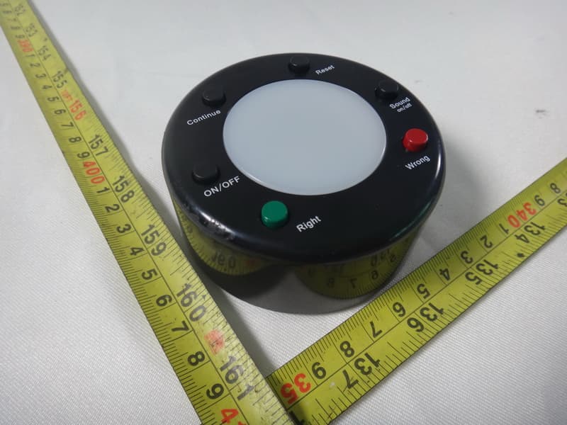
PKX1301GAMFX
Nov 08, 2012Personal Answer Pad
Equipment Class
DSS - Part 15 Spread Spectrum Transmitter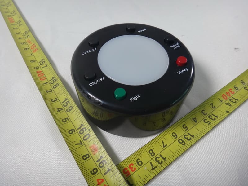
PKX1301GAMFZ
Nov 08, 2012Facilitator Control Unit
Equipment Class
DSS - Part 15 Spread Spectrum Transmitter
PKXTW63-P
Mar 28, 2010WHO'S FIRST-TOUCH PAD
Equipment Class
DXX - Part 15 Low Power Communication Device Transmitter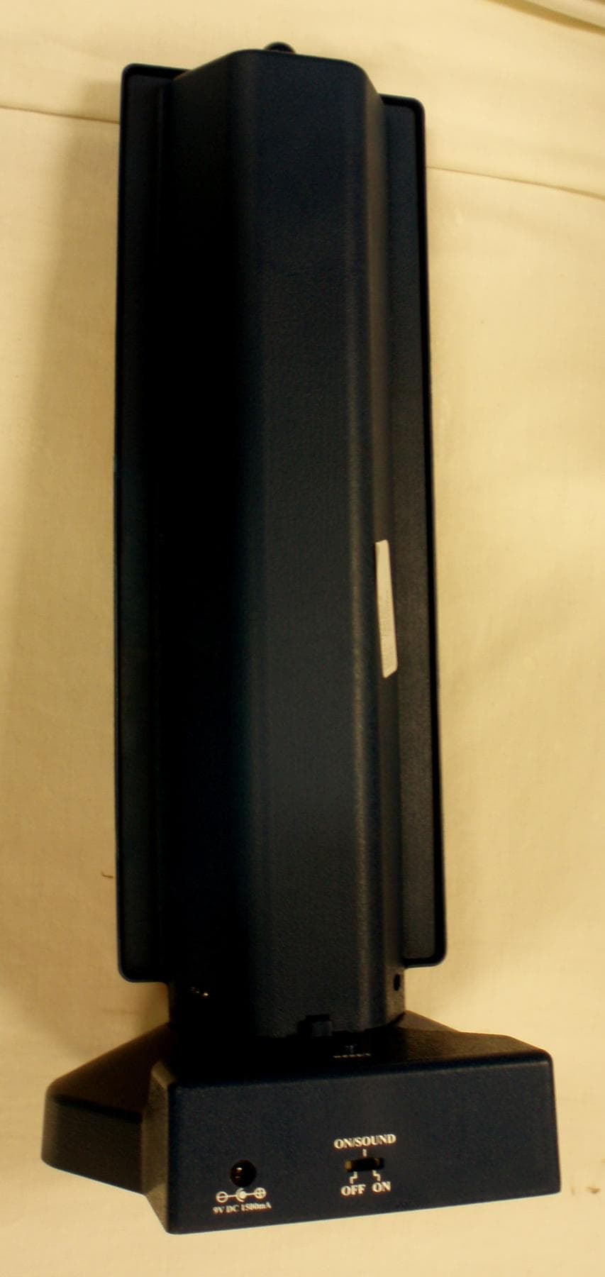
PKXTW63
Mar 28, 2010WHO'S FIRST-TOWER
Equipment Class
DXX - Part 15 Low Power Communication Device Transmitter