PLJWS260Remote transmitter for temperature measurement
Mandolyn Electronic Technology Inc.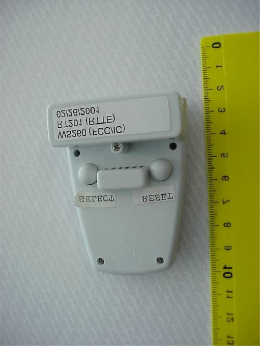
Click to zoom
Application Details
- Equipment Class
- DSC - Part 15 Security/Remote Control Transmitter
- Date of Grant
- Jun 18, 2001
- Application Purpose
- Original Equipment
- Date of Application
- Apr 14, 2001
- Equipment Note
- Remote transmitter for temperature measurement
- Frequency Range
- 433.90000000 - 433.90000000
- Country
- Canada
Documents & Files
Document Text
Text extracted from the exhibit documents filed with the FCC. Open a document above to read the original.
Users Manual
Operation of Thermo Station The LCD display of the Thermo Station can be divided into 3 sections: Upper and Lower thermo display and clock display area. The various functions are arranged in a circular pattern as shown below and are displayed on the bottom display area: Clock Mode —> Alarm Mode —> Countdown Timer Mode —> Date Mode —> Clock Mode... To shift from one mode to the other, press the MODE key. The display will return to Clock Mode automatically if no key is pressed for 1 minute. For the Temperature / Humidity Display, they are displayed on the top 2 sections. Functions of Thermo Station Setting the Clock 1.To enter Clock-setting mode, press SET key in the Clock Mode and the Hour field will flash as in Figure 1. 2.Press the ⇑(MODE) key or the ⇓(CHANNEL) key to increase or decrease its value. 3.To confirm the entry and move to the next field, press the SET key and the next field will be flashing. 4.Repeat Step (2) and Step (3) until all the data have been set. 5.For the value of Second, it can be set either to ”00” of the present minute (⇓), or ”00” of the next minute (⇑) 6.To switch between 12- and 24-Hour display format, press the ST/SP key in the Clock-setting mode. 7.After all data are set, the display will return to the Clock Mode. Setting the Alarm 1.To enter Alarm-setting mode, press the SET key in the Alarm mode and the Hour field will flash as in Figure 2. 2.Press the ⇑(MODE) key or the ⇓(CHANNEL) key to increase or decrease its value. 3.To confirm the entry and move to the next field, press the SET key and the next field will be flashing. 4.Repeat Step (2) and Step (3) until hour and minute have been set. 5.To confirm the entry, press the SET key again. 6.To activate the alarm, press the ST/SP key in the Alarm or Alarm-setting mode. A beep will sound and ”ON” will be displayed indicating that the alarm is on as in Figure 3. To de-activate the alarm, press the ST/SP key again. 7.Alarm will sound for 1 minute when alarm time has arrived. Press any key to stop the alarm (Snooze Function: If the SNOOZE key is pressed, the alarm sound will stop and re-generate after every 5 minutes until other key is pressed to stop the alarm sound). Setting the Kitchen Countdown Timer 1.To enter Kitchen Countdown Timer setting mode, press the SET key in the Kitchen Timer mode and the Hour field will flash as in Figure 4. 2.Press the ⇑(MODE) key or the ⇓(CHANNEL) key to increase or decrease its value. 3.To confirm the entry and move to the next field, press the SET key and the next field will be flashing. 4.Repeat Step (2) and Step (3) until all the data have been set. 5.The range of countdown display is from 1 second up to 23 hours 59 minutes and 59 seconds. 6.To start the countdown, press the ST/SP key in the Kitchen Countdown Timer mode or its setting mode. A beep sound indicates that the countdown has started. 7.Press the ST/SP key during countdown will pause the process. To resume countdown, press the ST/SP key again. 8.Countdown will continue even when you exit the Kitchen Countdown Timer mode. 9.When Countdown is finished, the display will jump to the Kitchen Countdown Timer mode and alarm sound will be generated for 1 minute. Press any key to stop the alarm (Snooze Function: If the SNOOZE key is pressed, the alarm sound will stop and re-generate after every 5 minutes until other key is pressed to stop the alarm sound). Local Temperature Display 1.With the built-in sensor, the local temperature of the Thermo Station will be displayed on the middle section. 2.The range of temperature display is between -25°C to +50°C with a resolution of 0.1°C. “HI” or “LO” will be displayed if temperature is out of range. 3.To switch between °C and °F display, press the ST/SP key in the Clock mode. 4.To scroll through the displays of Current Temperature, Maximum Temperature, Minimum Temperature recorded and Temperature alarm mode, press the SNOOZE key. “MAX” and “MIN” symbol will indicate the corresponding mode. (Figure 5 and Figure 6) 5.To clear the records of Maximum and Minimum Temperature, press and hold the ST/SP key for 3 seconds. A beep will sound and the data will be cleared. Both local and remote temperature data will be cleared. Remote Temperature Display & Humidity Display (Optional) by RF-Technology (Frequency: 433MHz) 1.By RF technology, the Thermo Station can act as a Receiver and receive remote signals from up to 4 Remote Transmitters (RT-101) which can be placed wherever you desire within the transmission range. 2.To enable the Thermo Station to receive signals from each Remote Transmitter, identical House code must be set to all transmitters and different Channel numbers must be assigned to each Remote Transmitter in use. To achieve this, please follow the procedures below to setup the Remote Transmitter(s) for use with the Thermo Station. Remote Temperature Display 1.By using RF technology and simple Learn function, the Thermo Station can receive remote signals from up to 4 Remote Transmitters (WS260) which can be placed indoor / outdoor wherever you desire within the transmis- sion range. 2.To enable the Thermo Station to receive signals from each Remote Transmitter, identical House Code and different Channel Numbers must be assigned to each Remote Transmitter in use. Please follow the procedures below to set the Remote Transmitter(s) to work with the Thermo Station. Setting the Remote Transmitter(s) 1.There are 2 buttons at the back of transmitter. Press the RESET button (right side) to start the setting procedure. 2.House Code will be flashing with “01” as in Figure 7. If desired, press SET button (left side) to change the House Code. 3.The range of House Code is from “01” to “15”. Make sure all transmitters in your system are set to the same House Code. 4.The House Code will be confirmed if no key is pressed for 10 seconds. Channel Number will start to flash with “1” as in Figure 8. 5.Use the SET button to select different Channel Number (1 – 4) for each of your transmitter. 6.Th…
Text truncated - open the document above for the full version.
Cover Letter(s)
Mandolyn Thermo Station: This equipment system consist of four components: one transmitter and three receivers. It is used to send temperature information to a remote receiver. Tthe transmitter is packaged with one of the three receivers for ge neral sales. The transmitter is designed to operate under the provisions of Section 15.231(e) which provides an exemption from certain types of communication that is prohibited at the higher power levels provided for in Section 15.231. Section 15.231(e) also provides an exemption from the periodic rate requirements in 15.231(a) to permit higher periodic rates. The maximum transmission rate is one word of 210 milliseconds with a silent period of at least 60 seconds between transmissions. The unit is battery powered. Phillip Inglis Consultant to Mandolyn
Cover Letter(s)
Mandolyn Thermo Station: This equipment system consist of four components: one transmitter and three receivers. It is used to send temperature information to a remote receiver. Tthe transmitter is packaged with one of the three receivers for general sales. The transmitter is designed to operate under the provisions of Section 15.231(e) which provides an exemption from certain types of communication that is prohibited at the higher power levels provided for in Section 15.231. Section 15.231(e) also provides an exemption from the periodic rate requirements in 15.231(a) to permit higher periodic rates. The maximum transmission rate is one word of 210 milliseconds with a silent period of at least 60 seconds between transmissions. The unit is battery powered. Phillip Inglis Consultant to Mandolyn
External Photos
CETECOM ICT Services GmbH Test report nr..: 5-3355-A/01Issue Date: 19.03.01Page 19 (33) Photographs of the equipment: Transmitter WS260 Photograph no.: 2 CETECOM ICT Services GmbH Test report nr..: 5-3355-A/01Issue Date: 19.03.01Page 20 (33) Photographs of the equipment: Transmitter WS260 Photograph no.: 3
ID Label/Location Info
The above is the format of the FCC ID label. The X’s represent the FCC ID grantee code and product code. The label will be located on the bottom of the unit as depicted below. Bottom of unit. ID Label
Internal Photos
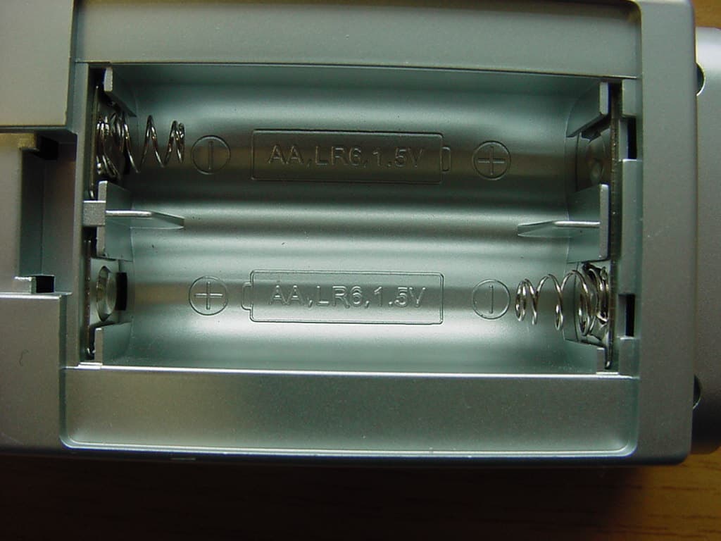
CETECOM ICT Services GmbH Test report nr..: 5-3355-A/01Issue Date: 19.03.01Page 21 (33) Photographs of the equipment: Transmitter WS260 Photograph no.: 4 CETECOM ICT Services GmbH Test report nr..: 5-3355-A/01Issue Date: 19.03.01Page 22 (33) Photographs of the equipment: Transmitter WS260 Photograph no.: 5
Parts List/Tune Up Info
RT201/WS260 THERMO TRANSMITTER 3V Revised: November 29, 2000 RT201 PCB Revision: A Bill Of Materials November 29, 2000 16:00:57 Page 1 Item Quantity Reference Part _____________________________________________________ 2 2 C5,C6 0.1U SMD 0603 3 2 C2,C3 22P NPO SMD 0603 4 1 C4 0.22U 10% SMD 0603 5 1 FB1 FB 6 1 LCD1 LCD HD9094 8 1 R1 10K 0603 RES 9 1 R2 20K 0603 RES 10 1 R3 10K 1% 0603 RES 11 1 R4 1K 0603 RES 12 1 R5 HUMID SENSOR HS-12P 13 1 R6 1M 0603 RES 14 1 R7 820K 0603 RES 15 1 R8 THERMISTOR 103AT 16 1 R9 47 0603 RES 17 2 S1,S2 RUBBER KEY 19 1 U1 CPU097 20 1 U2 HT7027A 21 1 Y1 32768HZ RF SECTION: 22 2 C7,C19 100P 0603 SMD 23 3 C8,C12,C15 2.7P NPO 0603 SMD 24 1 C9 2.2P NPO 0603 SMD 25 1 C13 0.5P NPO 0603 SMD 26 3 C11,C13,C18 2.7P NPO 0603 SMD 27 1 C14 8.2P NPO 0603 SMD 28 2 C16,C17 0.01U 0603 SMD 29 1 C20 2~5P NPO TRIMMER CAP 30 1 L2 2.5T COIL 31 1 L3 5.5T COIL 32 1 L4 4.5T COIL 33 2 Q1,Q2 TRANSISTOR KST10 34 2 R10,R12 8.2K 0603 RES 35 1 R11 6.8K 0603 RES 36 1 R13 68 0603 RES 37 1 R14 10 0603 RES 38 1 R15 24 0603 RES 39 1 R16 4.7K 0603 RES 40 1 Y2 SAW RESONATOR 433.92MHZ 41 1 PCB RT201 PCB
Schematics
Thursday , March 01, 2001 RT201RF PCBRT201/WS260 TRANSMITTER 433MHZ MANDOLYN ELECTRONIC TECHNOLOGY INC. A 10 TitleSize Document Number Date: Sheet of RT201RF.SCH ANT PRINTEDON P.C.B R16 4.7K C19 100P R10 8.2K Q2 KST10 R13 68 C15 2.7P NPO C9 2.2P NPO C7 100P Y2 433.92MHz C1820P NPO R14 10 C16.01 L2 2.5T R116.8K R128.2K R15 24 C1320PNPO L4 23.2uH C17.01 C13 0.5P NPO L3 5.5T Q1 KST10 C1120PNPO C8 2.7P NPO C12 2.7P NPO C20SEMI 2~5PNP0 C14 8.2P NPO +3v GND DATA
Test Report
CETECOM ICT Services GmbH Radio Satellite Communication Untertürkheimer Straße 6-10 . D-66117 SaarbrückenTelefon: +49 (0)681 598-0Telefax: -9075 RSC14issue test report consist of 33 PagesPage 1 (33) Test report no.: 5-3355-A/01 FCC Part 15.231 MANDOLYN Thermostation WS 260,WS 220, WS 240 and WS 410 Accredited Testing Laboratory DAR-Registration number: TTI-P-G 166/98-00 CETECOM ICT Services GmbH Test report nr.: 5-3355-A/01Issue date:19.03.01Page 2 (33) Table of Contents 1 General information 1.1 Notes 1.2 Testing laboratory 1.3 Details of applicant 1.4 Application details 1.5 Test item 1.6 Test standards 2 Technical test 2.1 Summary of test results 2.2 Test report 1 General information 1.1 Notes The test results of this test report relate exclusively to the test item specified in 1.5. The CETECOM ICT Services GmbH does not assume responsibility for any conclusions and generalisations drawn from the test results with regard to other specimens or samples of the type of the equipment represented by the test item. The test report may only be reproduced or published in full. Reproduction or publication of extracts from the report requires the prior written approval of the CETECOM ICT Services GmbH. 1.2Testing laboratory CETECOM ICT Services GmbH Untertürkheimer Straße 6 - 10 66117 Saarbrücken Germany Telefone: + 49 681 598 - 0 Telefax : + 49 681 598 - 9075 E-mail: [email protected] Internet: www.cetecom.de Accredited testing laboratory DAR-registration number : TTI-P-G 166/98-00 CETECOM ICT Services GmbH Test report nr.: 5-3355-A/01Issue date:19.03.01Page 3 (33) 1.3Details of applicant Name :Mandolyn Electronic Technology Inc. Street :108-250 Shields CRT. City :Markham, Ontario, L3R 9W7 Country :CANADA Telephone:+905 305 0923 Telefax :+905 305 0924 Contact :Mr. CM Yip Telephone:+905 305 0923 1.4Application details Date of receipt of application : 07.03.2001 Date of receipt of test item : 07.03.2001 Date of test : 09.03.- 19.03.2001 1.5Test item Type of equipment : Wireless Thermostation Type designation: WS 260, WS 220, WS 240, WS 410 Manufacturer:applicant Street: City: Country: Serial number: Additional informations:: Frequency:433,925 MHz Type of modulation:20K0A1D Number of channels :1 Antenna:integral print antenna Power supply:TX: 3V DC, RX: 3V DC Output power:max 68 dBμV/m at 3m Type of equipment:Temperature range : -20°C - +55°C 1.6Test standards: FCC Part 15 §15.231 CETECOM ICT Services GmbH Test report nr.: 5-3355-A/01Issue date:19.03.01Page 4 (33) 2 Technical test 2.1Summary of test results The thermostation family consists of one transmitter and three receivers that use all the same RX-board. The same TX (WS260) is sold either with WS220 , WS240 or WS410. The radiated measurements were performed vertical, horizontal results are about 5 dB lower over the whole frequency range. All measurement settings are according to FCC 15.35, 15.205, 15.207, 15.209 and 15.231. Measurements below 1 GHz were performed with a CISPR Quasi Peak Adapter, over 1 GHz we used peak measurements. At peaks we did an second, average measurement. ResBW and VBW were according FCC requirements. No deviations from the technical specification(s) were ascertained in the course of the tests performed. Technical responsibility for area of testing : 23.03.01RSC 8414Ames H. DateSectionNameSignature Technical responsibility for area of testing : 23.03.01RSC8411Berg M. DateSectionNameSignature CETECOM ICT Services GmbH Test report nr.: 5-3355-A/01Issue date:19.03.01Page 5 (33) 2.2Testreport TEST REPORT Testreport no. : 5-3355-A/01 CETECOM ICT Services GmbH Test report nr.: 5-3355-A/01Issue date:19.03.01Page 6 (33) TEST REPORT REFERENCE LIST OF MEASUREMENTS ParagraphPARAMETER TO BE MEASUREDPAGE Transmitter parameters §15.231 (a) (2) Automatic deactivation7 § 15.231 (e)Time of occupancy8 § 15.231 (c) Bandwidth of emission9 § 15.231 (e) Restricted field stregth for periodic TX 10 § 15.231 (e) Restricted field stregth for spurious 10 Receiver parameters § 15.209Spurious radiations - Radiated11 Test equipment listing15 Photographs of the equipment17 CETECOM ICT Services GmbH Test report nr..: 5-3355-A/01Issue Date:19.03.01Page 7 (33) Equipment under test : WS 260, WS 220, WS 240 and WS 410 Ambient temperature: 20°C Relative humidity : 31% REFERENCE NUMBER(S) OF TEST EQUIPMENT USED (for reference numbers see test equipment listing) - Automatic deactivationSUBCLAUSE §15.231 (a) (2) SUBCLAUSE §15.231 (e) The transmitter is activated automatically every 60 seconds for a duration of 210.9 ms. Encoding:2 pulses of 0.976 ms for low, 0.976 ms high for logic 1 1 pulse of 1.952 ms low, 1.952 ms high for logic 0 Word format: 36 bits/word (70.3 ms) Operating period: One transmission of 3 words (3*70.3 ms) every 60 s. So we have 3*70.3 ms = 210.9 ms every 60 s. CETECOM ICT Services GmbH Test report nr..: 5-3355-A/01Issue Date:19.03.01Page 8 (33) Equipment under test : WS 260, WS 220, WS 240 and WS 410 Ambient temperature: 20°C Relative humidity : 31% REFERENCE NUMBER(S) OF TEST EQUIPMENT USED (for reference numbers see test equipment listing) 64 Time of occupancy§ 15.231 (e) Cursor 1 to cursor 2 ~60.1 s; cursor 2 to cursor 3 ~60.1 s etc. Ref Lvl -20 dBm Ref Lvl -20 dBm RBW 100 kHz VBW 100 kHz RF Att 10 dB A UnitdBmSWT 300 s Center 433.9 MHz30 s/ 1VIEW1AP -120 -110 -100 -90 -80 -70 -60 -50 -40 -30 -20 1 1 23 Delta 1 [T1] -4.06 dB 60.120240 s 1 [T1] -48.71 dBm 3.006012 s 1 [T1] -4.06 dB 60.120240 s 2 [T1] 0.88 dB 120.240481 s 3 [T1] 0.79 dB 180.360721 s Date: 13.MAR.2001 08:19:06 CETECOM ICT Services GmbH Test report nr..: 5-3355-A/01Issue Date:19.03.01Page 9 (33) Equipment under test : WS 260, WS 220, WS 240 and WS 410 Ambient temperature: 20°C Relative humidity : 31% REFERENCE NUMBER(S) OF TEST EQUIPMENT USED (for reference numbers see test equipment listing) 64 Bandwidth of Emission§ 15.231 (c) The red threshold line shows the relative maximum peak output power. The red reference line is –20 dBc. Both cursors are at the crossin…
Text truncated - open the document above for the full version.
Test Setup Photos
CETECOM ICT Services GmbH Test report nr..: 5-3355-A/01Issue Date: 19.03.01Page 14 (33) Test site RADIATED EMISSIONS CETECOM ICT Services GmbH Test report nr..: 5-3355-A/01Issue Date: 19.03.01Page 15 (33) Test site RADIATED EMISSIONS CETECOM ICT Services GmbH Test report nr..: 5-3355-A/01Issue Date: 19.03.01Page 16 (33) Test site RADIATED EMISSIONS CETECOM ICT Services GmbH Test report nr..: 5-3355-A/01Issue Date: 19.03.01Page 17 (33) Test site RADIATED EMISSIONS CETECOM ICT Services GmbH Test report nr..: 5-3355-A/01Issue Date: 19.03.01Page 18 (33) Photographs of the equipment: Thermostation family Photograph no.: 1
Contact Information
Applicant
C.M. Yip(Engineering Manager)
Technical Contact
TRP/Cetecom bvbaPhillip Inglis
[email protected]410-521 3439
14085 Howard Rd · Dayton, Maryland · United States
Non-Technical Contact
TRP/Cetecom bvbaPhillip Inglis
[email protected]410 531 3439
Test Firm
Cetecom ICT Services GmbHRalf Hoehn
Technical Specifications
| # | Rule Parts | Frequency Range | Power Output |
|---|---|---|---|
| 1 | 15C | 433.9 MHz - 433.9 MHz | - |
Other Applications from Mandolyn Electronic Technology Inc.
PLJDB910
Jul 03, 2007Wireless Doorbell
Equipment Class
CYY - Communications Receiver used w/Pt 15 Transmitter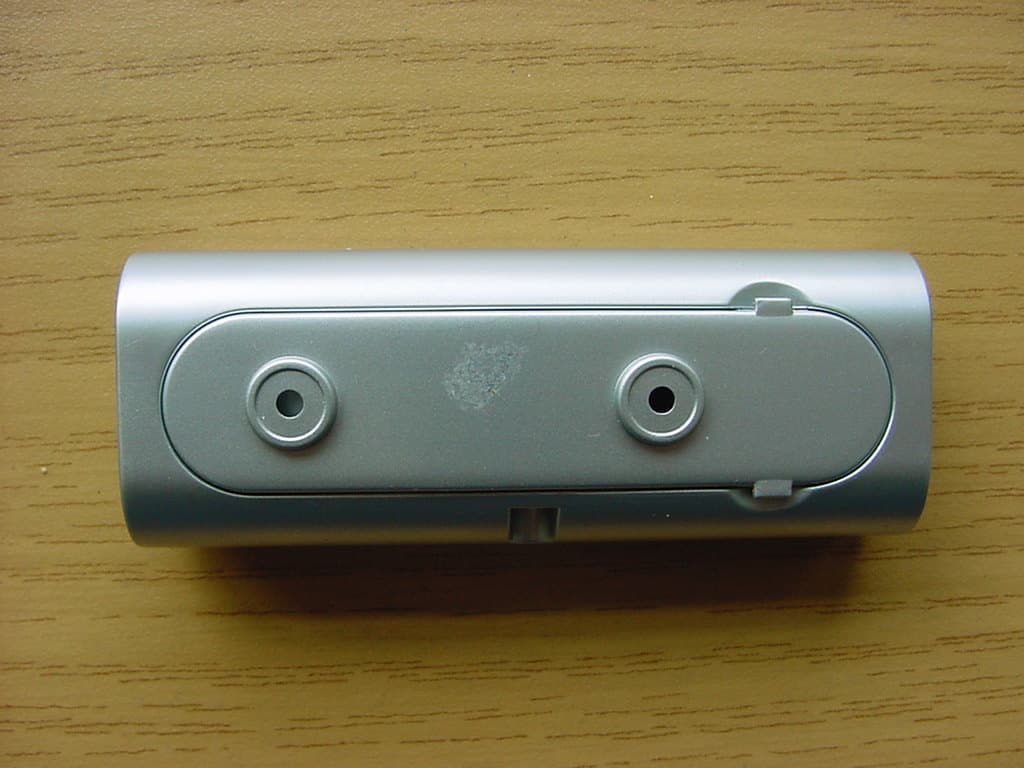
PLJDBT701
Jul 03, 2007Wireless Doorbell
Equipment Class
DSC - Part 15 Security/Remote Control Transmitter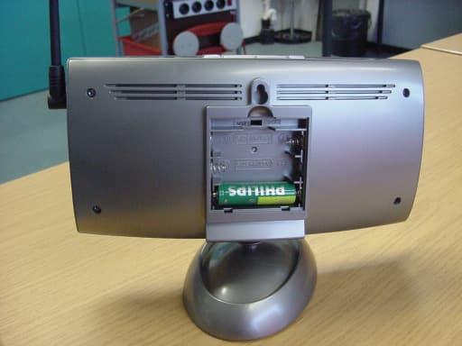
PLJWS2635
Mar 13, 2007Weather Station Receiver
Equipment Class
CRR - Superregenerative Receiver
PLJWDS500
Mar 13, 2007Weather Station Transmitter
Equipment Class
DSC - Part 15 Security/Remote Control Transmitter
PLJWS1200
Mar 13, 2007Weather Station Receiver
Equipment Class
CRR - Superregenerative Receiver