PLJWS330Weather Station Receiver
Mandolyn Electronic Technology Inc.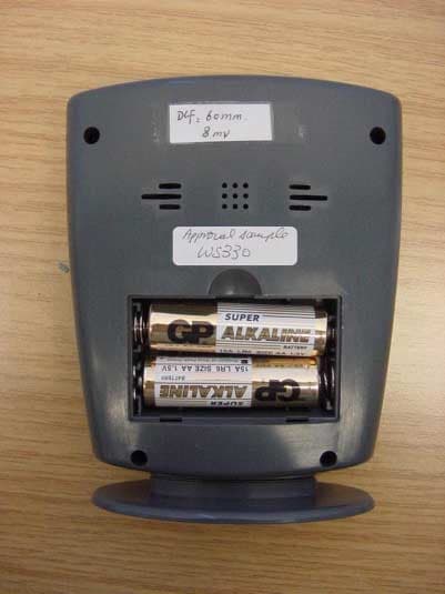
Click to zoom
Application Details
- Equipment Class
- CRR - Superregenerative Receiver
- Date of Grant
- Dec 04, 2002
- Application Purpose
- Original Equipment
- Date of Application
- Dec 04, 2002
- Equipment Note
- Weather Station Receiver
- Frequency Range
- 433.92000000 - 433.92000000
- Country
- Canada
Documents & Files
Document Text
Text extracted from the exhibit documents filed with the FCC. Open a document above to read the original.
Users Manual
28.4 c 1 28.4 c 1 WS330 + WT440H Wireless Weather Station GETTING STARTED battery installation GETTING STARTED 1 1 2 remove battery cover 2 AA size batteries (WS330) 2 AA size batteries (WT440H) Insert between terminals observing proper polarity then replace cover LOW BATTERY INDICATION: Low battery indication will be indicated by flashing trend box on the receiver (for both indoor & outdoor). On transmitter, will be displayed button placement 1 2 3 4 1 2 3 4 5 CHANNEL - scrolls through remote channels 1-4 ALARM/ (AM/PM)/ (C/F) - toggles between C and F, 12 and 24 hour format, turns alarm on/off; clears temperature alarm presets MODE/SNOOZE - scrolls through time, alarm and temperature alarm set points (high/low); activates alarm snooze UP/HOUR/MAX - scrolls through hours; shows maximum temperature DOWN/MINUTE/MIN - scrolls through minutes; show minimum temperature WS330 receiver WT440H transmitter 1 Press & hold ALRAM/(AM/PM)/(C/F) for 3 seconds to start. 2 Beep sound indicates that learn function has started. 3 CHANNEL symbol will flash and unit will beep as each transmitter is detected. 3 1 4 5 Insert batteries to start setup HOUSE CODE will flash for 8 seconds Select HOUSE CODE (1-15) by pressing CHANNEL will flash for 8 seconds Select CHANNEL(1-4) by pressing C/F 2 Transmitters for each receiver must be set to the same HOUSE CODE 6 7 Humidity & Temperature will display Select C or F of Temperature by pressing C/F key setting remote transmitters clock setting 3 1 4 5 Press and hold MODE until time flashes Select hour using HOUR Select minute using MINUTE Press AM/PM to toggle between 12 or 24 hour format Press MODE to finish setting 2 CLOCK & ALARM SETTING alarm setting 3 * Select alarm mode using MODE Select hour using HOUR Select minute using MINUTE In alarm mode, press ALARM to toggle alarm On and Off 2 1 4 5 c b Modes are arranged in a circular pattern starting with clock: * * clock alarm clock high temperature alarm low temperature alarm Congratulations on your purchase of this weather station set, WS330 + WT440H. Please take the time to read and understand this manual so you can begin to enjoy the convenience and features this product has to offer. FEATURES Main Display Unit WS330: * 12/ 24 hour clock and alarm * local temperature display * receives and displays temperature and humidity readings from up to 4 remote transmitter via RF technology of 433MHz * minimum and maximum temperature record * high/ low temperature alarm function * temperature and humidity trend indicator * weather report symbols * user-selectable C or F * battery type: 2 x AA Remote Transmitter WT440H * drip-proof design with LCD * socket of external sensor probe * temperature display in user-selectable C or F * humidity display * transmission range: up to 40 meters in open area * battery type: 2 x AA OWNERS MANUAL high temperature alarm SPECIFICATIONS Weather Station Receiver WS330 Battery Type:2 X 1.5V AA batteries Temp. Range:-20C to +55C Weather Station Transmitter WT440H Battery Type:2 X 1.5V AA batteries Temp. Range:-30C to +70C Humidity Range:15 to 95% Transmission Frequency:433.92 MHz Transmission Range:up to 40 meters in open area TEMPERATURE ALARM The temperature alarm function allows you to have an alarm sound if the temperature rises above or drops below a particular set point. low temperature alarm to clear high/low temperature alarm 1 Select high/low temperature alarm set point using MODE 2 Press ALARM to clear value Press MODE to finish setting 3 OTHER FEATURES 1 2 Toggle between current and maximum temperature using MAX Press CHANNEL to view the maximum temperature for other channels to view minimum temperature 1 2 Toggle between current and minimum temperature using MIN Press CHANNEL to view the minimum temperature for other channels to view maximum temperature 2 1 2 1 1 4 3 1 1 3 1 4 2 1 When alarm sounds, the sounding channel is displayed, and or flashes to indicate whether it is the high or low temperature alarm. Press any button to shut off alarm. 1 Select high temperature alarm mode using MODE 3 Press DOWN or UP to set high temperature Press MODE to finish setting 4 2 Select channel (1, 2, 3, 4 or local) using CHANNEL * Once the high/low temperature alarm is set for a particular channel, and/or will appear on display for that channel 1 Select low temperature alarm mode using MODE 3 Press DOWN or UP to set low temperature Press MODE to finish setting 4 2 Select channel (1, 2, 3, 4 or local) using CHANNEL * 3 2 2 The trend indicator shows the trend of temperature and humidity determined by the particular transmitter in the past half-hour interval. The receiver is able to monitor and display the weather status based on collected data from Channel 1. About Freeze Warning * Snow symbol will flash to warn of 'freezing'. * Activated when Channel 1's temperature is between -1.9 C and +2.9 C * Snow will appear solid if and when Channel 1's temperature falls below -1.9 C. Note: * Initially, the weather will be cloudy * Remote transmitter Channel 1 will be used for weather indication. * If Channel 1 is empty, then weather will always be cloudy. * If Channel 1 has no humidity data, weather indication will always be cloudy, but freeze warning and snow indication will be available. weather report symbols WEATHER DISPLAY Arrow Indicator Rising Steady Falling Trend Weather Indicator OR OR temperature & humidity trend Raining Snowing Sunny Cloudy Freeze Warning <flashing snow> Check Remote Temperature & Humidity Check Local Temperature C or F Temperature Display Min and Max Temperature A * B C D WEATHER DISPLAY Press CHANNEL to toggle between Channel 1, 2, 3 and 4. Temperature and humidity readings will alternate on the receiver. Local temperature displays instantly after batteries are inserted. Toggle between C and F by pressing C/F in clock mode. Press MIN in Clock mode to display minimum temperature record Press MAX in Clock mode to display maximum temperature record Note: Min/Max temperature record…
Text truncated - open the document above for the full version.
External Photos
CETECOM ICT Services GmbH Test report no.: 2_3083-01-03/02Issue Date: 2002-12-03Page 16 (19) Photographs of the equipment Photograph no.: 1 CETECOM ICT Services GmbH Test report no.: 2_3083-01-03/02Issue Date: 2002-12-03Page 17 (19) Photographs of the equipment Photograph no.: 2
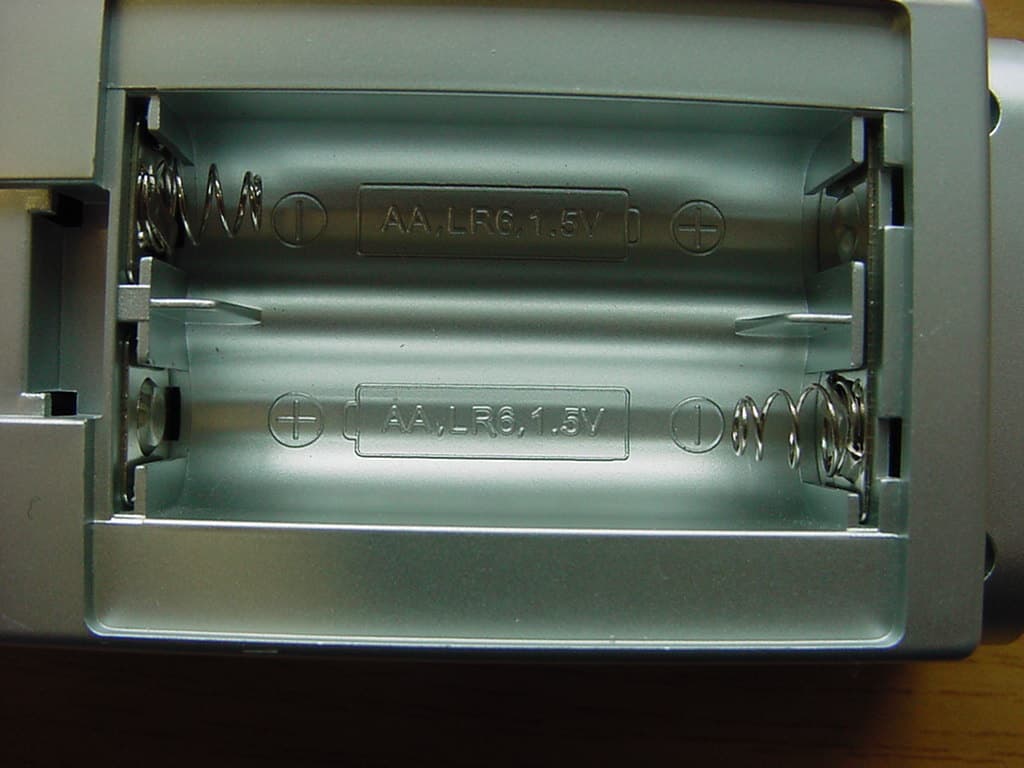
Internal Photos
CETECOM ICT Services GmbH Test report no.: 2_3083-01-03/02Issue Date: 2002-12-03Page 18 (19) Photographs of the equipment Photograph no.: 3 CETECOM ICT Services GmbH Test report no.: 2_3083-01-03/02Issue Date: 2002-12-03Page 19 (19) Photographs of the equipment Photograph no.: 4
Test Report
CETECOM ICT Services GmbH Radio Satellite Communication Untertürkheimer Straße 6–10, D-66117 Saarbrücken, Telephone +49 (0) 681 598- 0, Fax +49 (0) 598 9075 Test report No.: 2_3083-01-03/02This test report consists of 27 pagesPage 1 (19) Recognized by the Federal Communications Commission FCC–Identification Number: 90462 TCB ID: DE 001 Accredited by the German Accreditation Council DAR–Registration Number TTI–P–G 166/98 Independent ETSI compliance test house ETSI Accredited Bluetooth™ Test Facility (BQTF) Test report No. : 2_3083-01-03/02 Applicant : Mandolyn Int. Ltd. Type : WS330 FCC–ID No : PLJWS330 BLUETOOTH is a trademark owned by Bluetooth SIG, Inc. and licensed to CETECOM CETECOM ICT Services GmbH Test report No.: 2_3083-01-03/02Date: 2002-12-03Page 2 (19) Table of contents 1 General information 1.1 Notes 1.2 Testing laboratory 1.3 Details of applicant 1.4 Application details 1.5 Test item 1.6 Test specifications 2 Technical test 2.1 Summary of test results 2.2 Test report CETECOM ICT Services GmbH Test report no.: 2_3083-01-03/02Issue Date: 2002-12-03Page 3 (19) 1 General information 1.1 Notes The test results of this test report relate exclusively to the test item specified in 1.5. The CETECOM ICT Services GmbH does not assume responsibility for any conclusions and generalisations drawn from the test results with regard to other specimens or samples of the type of the equipment represented by the test item. The test report may only be reproduced or published in full. Reproduction or publication of extracts from the report requires the prior written approval of the CETECOM ICT Services GmbH. Test laboratory manager: 2002-12-03RSC - 8411Berg M.. DateSectionNameSignature Technical responsibility for area of testing: 2002-12-03RS - 8412Hausknecht D. DateSectionNameSignature CETECOM ICT Services GmbH Test report no.: 2_3083-01-03/02Issue Date: 2002-12-03Page 4 (19) 1.2 Testing laboratory CETECOM ICT Services GmbH Untertürkheimer Straße 6 - 10 66117 Saarbrücken Germany Telephone: + 49 681 598 - 0 Telefax : + 49 681 598 - 9075 E-mail: [email protected] Internet: www.cetecom-ict.de Accredited testing laboratory Accredited by: Regulierungsbehörde für Telekommunikation und Post (RegTP) Listed by: Federal Communications Commission (FCC) AuthorityIdentification/Registration No. RegTPTTI-P-G 166/98-30 FCC90462 1.3Details of applicant Name :W.H. Mandolyn International Ltd. Street :Unit 1003-8 Landmark North 39 Lung Sum Avenue; Sheung Shui City :N.T. Hong Kong Country :N.T. Hong Kong Telephone:+(852) 2670 9733 Telefax :+(852) 2673 0337 E-mail :[email protected] Contact person: Name : Shirley Chan Telephone : +(852) 2670 9733 Telefax : +(852) 2673 0337 E-mail : [email protected] 1.4Application details Date of receipt of test item : 2002-11-14 Date of test: 2002-12-03 Person(s) who have been : -.- present during the test CETECOM ICT Services GmbH Test report no.: 2_3083-01-03/02Issue Date: 2002-12-03Page 5 (19) 1.5Test item Type of equipment : Receiver Type designation:Model WS330 Manufacturer:Same as applicant Street: City: Country: Serial number:- / - Additional information : Frequency:433.92 MHz Type of modulation:A1D Channel spacing:>25 kHz Number of channels :1 Antenna:Integral antenna Power supply:2x 1.5 V Alkaline Batteries Temperature range :-20°C - +55°C FCC ID :PLJWS330 1.6Test specifications: FCC Part 15 §15.109 CANADA ICES0003 CETECOM ICT Services GmbH Test report no.: 2_3083-01-03/02Issue Date: 2002-12-03Page 6 (19) 2 Technical test 2.1 Summary of test results The radiated measurements were performed vertical and horizontal over the whole frequency range. We start at 1 m high with vertical receiving antenna and rotate the dish continuously. During rotation we use the antenna lift system to vary the high from 1 to 4 m. So we find maximum radiation output. At this points we do manual re-measurements. After this we do the same measurements in horizontal position of the receiving antenna. This (horizontal and vertical) is made for all the three planes of the test sample. We use the maximum received results. The detector function and selection of bandwidth are according ANSI C63.2-1996 item 8.2.1 and ANSI C63.4-1992 Item 4.2. Antennas are conform with ANSI C63.2-1996 item 15. 150 kHz - 30 MHz: Quasi Peak measurement, 9kHz Bandwidth, passive loop antenna. 30 MHz - 200 MHz: Quasi Peak measurement, 120KHz Bandwidth, biconical antenna 200MHz - 1GHz: Quasi Peak measurement, 120KHz Bandwidth, log periodic antenna 1GHz: Average, RBW 1MHz, VBW 10 MHz, waveguide horn All measurement settings are according to FCC 15.35, 15.205, 15.209, 15.109 . The product fulfills also the requirements for CANADA ICES0003 No deviations from the technical specification(s) were ascertained in the course of the tests performed. CETECOM ICT Services GmbH Test report no.: 2_3083-01-03/02Issue Date: 2002-12-03Page 7 (19) 2.2Test report TEST REPORT Test report no. : 2_3083-01-03/02 CETECOM ICT Services GmbH Test report no.: 2_3083-01-03/02Issue Date: 2002-12-03Page 8 (19) TEST REPORT REFERENCE LIST OF MEASUREMENTS ParagraphPARAMETER TO BE MEASUREDPAGE RECEIVER PARAMETERS § 15.109Spurious radiation - Radiated9 Test equipment listing13 Photographs of the equipment15 CETECOM ICT Services GmbH Test report No.: 2_3083-01-03/02Date: 2002-12-03Page 9 (19) Receiver EMISSION LIMITATIONS- Radiated § 15.109 EMISSION LIMITATIONS f (MHz) polari- zation amplitude of emission (dBμV/m) QUASIPEAK amplitude of emission (dBμV/m) average limit max. allowed emmision power (dBμV/m) results 463.34V35.146complies 1161.4V27.654complies Measurement uncertainty± 3dB Limits SUBCLAUSE § 15.109 Frequency (MHz)Field strength (μV/m)Measurement distance (m) 0.009 - 0.4902400/F(kHz)300 0.490 - 1.70524000/F(kHz)30 1.705 - 30.03030 30 - 881003 88 - 2161503 216 - 9602003 above 9605003 CETECOM ICT Services GmbH Test report no.: 2_3083-01-03/02Issue Date: 2002-12-03Page 10 (19) EMISSION LIMITATIONS- Radiated < 30 MHz § 15.109 …
Text truncated - open the document above for the full version.
Test Setup Photos
CETECOM ICT Services GmbH Test report no.: 2_3083-01-03/02Issue Date: 2002-12-03Page 15 (19) Test site
Contact Information
Applicant
C.M. Yip(Engineering Manager)
Test Firm
Cetecom ICT Services GmbHRalf Hoehn
Technical Specifications
| # | Rule Parts | Frequency Range | Power Output |
|---|---|---|---|
| 1 | 15B | 433.92 MHz - 433.92 MHz | - |
Other Applications from Mandolyn Electronic Technology Inc.
PLJDB910
Jul 03, 2007Wireless Doorbell
Equipment Class
CYY - Communications Receiver used w/Pt 15 Transmitter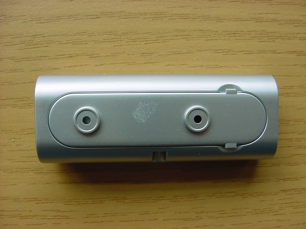
PLJDBT701
Jul 03, 2007Wireless Doorbell
Equipment Class
DSC - Part 15 Security/Remote Control Transmitter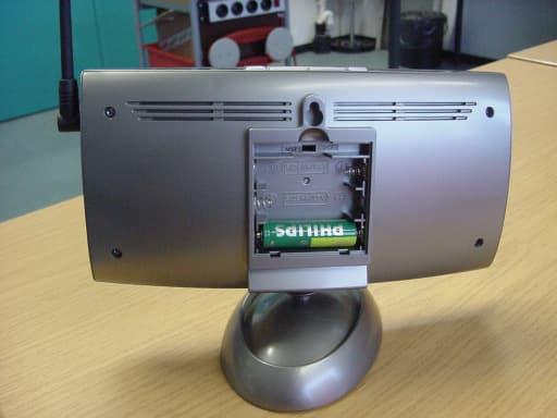
PLJWS2635
Mar 13, 2007Weather Station Receiver
Equipment Class
CRR - Superregenerative Receiver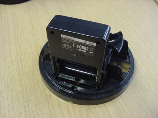
PLJWDS500
Mar 13, 2007Weather Station Transmitter
Equipment Class
DSC - Part 15 Security/Remote Control Transmitter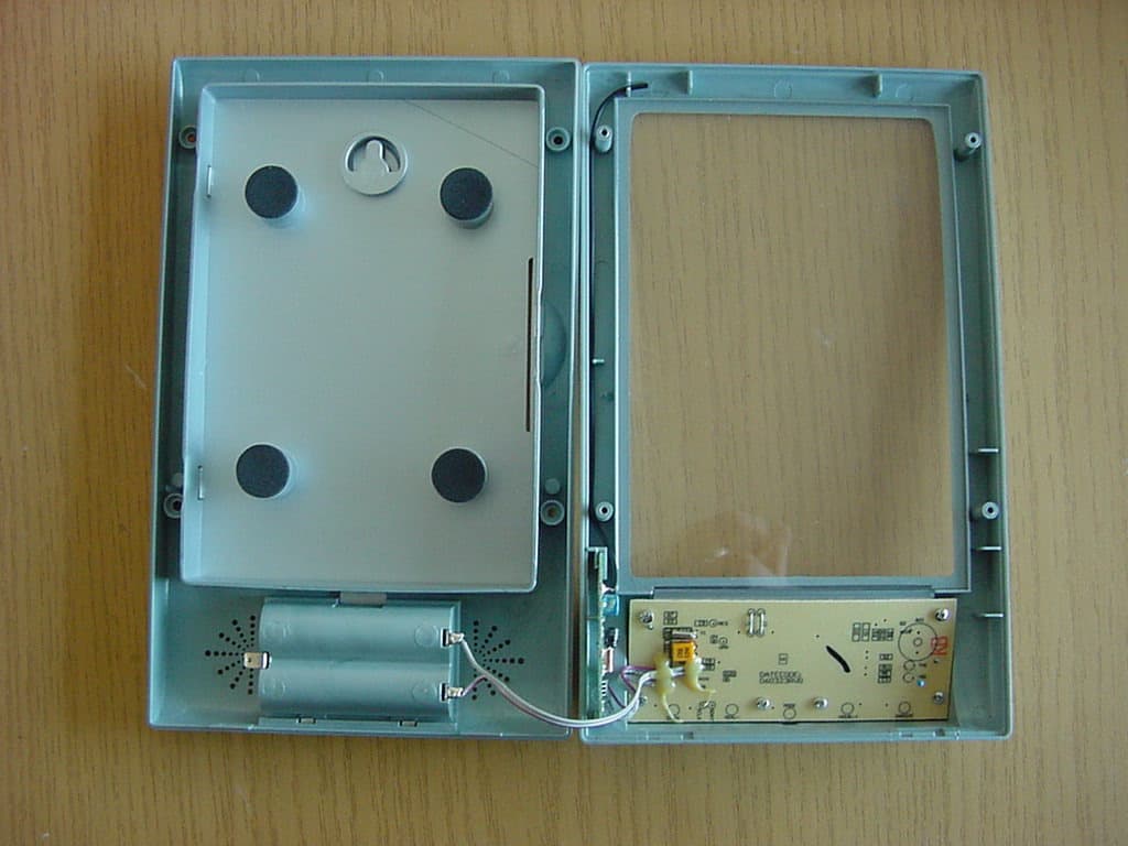
PLJWS1200
Mar 13, 2007Weather Station Receiver
Equipment Class
CRR - Superregenerative Receiver