PLJWS738Weather Station Receiver
Mandolyn Electronic Technology Inc.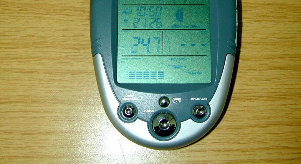
Click to zoom
Application Details
- Equipment Class
- CYY - Communications Receiver used w/Pt 15 Transmitter
- Date of Grant
- Jul 07, 2004
- Application Purpose
- Original Equipment
- Date of Application
- Jul 07, 2004
- Equipment Note
- Weather Station Receiver
- Frequency Range
- 433.92000000 - 433.92000000
- Country
- Canada
Documents & Files
Document Text
Text extracted from the exhibit documents filed with the FCC. Open a document above to read the original.
Users Manual
DST Setting User can manually select DST (daylight saving time) feature when DCF is failed to receive Scroll to Year mode using MODE Press ALARM manually to enable and disable DST When DST is set ON, the DST symbol will appear Date Setting: Scroll to date mode using MODE Press HOUR/+/MAX to set month Press MINUTE/-/MIN to set date Weekday is automatically determined from the year/month/day setting DATE, YEAR & ALARM SETTING 1 a 2 b 3 c d February will have either 28 or 29 days depending on the year setting Year Setting Scroll to YEAR mode using MODE Press + or - key to adjust year e f P.6 bc a e d f f Note: * It is not recommended unless DCF is failed to synchronize * It is recommended to change the year/month/day information accordingly 2 1 3 battery installation GETTING STARTED remove battery cover 2 AA size batteries (WS738) 2 AA size batteries (WT440H) (included) Insert between terminals observing proper polarity then replace cover setting remote sensors 1 1 Press SET to start House code will flash for 10 seconds 2 2 *Use a different house code if your weather station detects othersignals from neighbouring sources * Factory default: house code = 01 and channel = 01 3 3 4 4 5 Select house code (1-15) by pressing C/F key. Press SET to confirm. Channel will flash for 10 seconds Select channel(1-4) by pressing C/F key. Press SET to confirm. Remote sensors for each receiver must be set to the same house code. SET C/F - A A 1 . 5 V + - A A 1 . 5 V + 13b5b 3a5a WS738 Wireless Weather Station with weather forecast OWNERS MANUAL Congratulations on your purchase of this weather station, WS738. Please take the time to read and understand this manual so you can begin to enjoy the convenience and features this product has to offer. The WS738 is a weather station device that has several weather related functions. The main features are: WT440H remote sensor Main Display Unit: * * * * * * * * * * * * * * Remote Sensor WT440H: * * * * * Auto synchronizing radio controlled clock (DCF- 77) Perpertual Calendar Local temperature and humidity display Receives and monitors temperature and humidity from up to 4 remote sensors via RF technology of 433MHz Maximum/minimum temperature records Temperature and humidity trend indicator Temperature history chart Temperature alarm (for local and one out channel) Weather forecast display Moon phase symbols Sunrise/ Sunset time display Backlight User-selectable C or F Battery: 2 x AA size Splash proof design with LCD Temperature display in user-selectable C or F Humidity display Transmission range: up to 40 meters Battery: 2 x AA size GETTING STARTED button placement 1 7 6 8 9 2 3 4 5 MINUTE/-/MIN: shows minimum temperature; adjusts clock, alarm, date & year and temperature alarm values SNOOZE/MODE: scrolls through Clock 1 & 2, Alarm 1 & 2, Date & Year, and Temperature Alarm (high & low) mode; snooze for alarm SET: enter into setting mode and confirm the values during setting. C/F: change value of channel and house code during setting. Select between C or F. Battery compartment LCD display ALARM/(C/F): toggles between C and F, 12 and 24 hour format, Alarm 1 & 2 on and off; disables (resets) high & low temperature alarms; disable/enable backlight CHN: scrolls through remote channels (1 to 4); scrolls through local and remote channels (1 to 4) in (high & low) temperature alarm mode; set sunrise/sunset zone; activate learn process HOUR/+/MAX: shows maximum temperature; adjusts clock, alarm, date & year and temperature alarm values 7 8 9 SET C/F - A A 1 . 5 V + - A A 1 . 5 V + 6 Synchronization 1 1 2 2 3 4 SETUP Automatic Learn Function: Manual-Learn (Searching for Remote Signals): Learn function executes automatically and runs for approximately 3 minutes when batteries are first installed in the receiver. Press and hold CHN for 3 seconds to start If a new remote sensor is added or if signal is lost (outdoor display blinking), learn function must be executed again. Within these 3 minutes, receiver picks up the temperature & humidity signals from remote sensor and displays the readings. Beep sound indicates that learn function has started 'Channel' symbol will flash and unit will beep as each remote sensor is detected Temperature & humidity readings of remote sensor displays on the receiver. Auto/Manual Learn will not operate while the radio controlled clock is receiving DCF77 signals * Clock 1 Setting: Press and hold MODE for 3 seconds to enter the clock setting mode (the CLOCK 1 symbol appears and the time will flash) Press HOUR to set the hour and MINUTE to set the minute; Press ALARM/(C/F) during clock setting, to change between 12 and 24 hour display. This also will end clock setting. Press MODE or do not press any key for 1 minute to finish clock setting. Clock 2 Setting: Scroll to Clock 2 mode using MODE Press + or - key to change the hour (in one hour increments/decrements relative to Clock 1) CLOCK SETTING Radio Control Clock manual clock setting 1 i ii iii iv vi v The Ws738 is designed to automatically synchronize its calendar clock once it is brought within range of 1500km of the Frankfurt DCF77 radio signal. When the WS738 is within this range, its radio-control mechanism will override all manual settings. 2 When receiving radio signal, the Radio Tower symbol starts to blink. A complete reception generally takes several minutes, depending on the strength of the radio signal. 3 When the reception is complete, the Radio Tower symbol will stop blinking and remain solid. 4 For better reception, place the clock away from metal objects and electrical appliances (i.e. television, computer, monitor, etc.) to minimize interference. P.1 P.5P.7 P.4 P.8 + - + - SET C/F A A 1 . 5 V A A 1 . 5 V WS738 receiver 1 2 5 3 4 9 2 2 4 1 3 i iii iv vi ii OUT 1 RF WIRELESS WEATHER TRANSMITTER OUT 1 OUT 1 OUT 1 OUT 1 LOW BATTERY INDICATION: Receiver: Low battery indicator will display continuously when batteries need replacing Remote sensor: Low battery indicator will appear on sensor’…
Text truncated - open the document above for the full version.
External Photos
CETECOM ICT Services GmbH Test report no.:5-4812-01-04/04Issue date: 2004-07-05 Page 15 (21) PHOTOGRAPHS OF THE EQUIPMENT Photograph no.: 1 WS738 CETECOM ICT Services GmbH Test report no.:5-4812-01-04/04Issue date: 2004-07-05 Page 16 (21) PHOTOGRAPHS OF THE EQUIPMENT Photograph no.: 2 WS738
ID Label/Location Info
1:1 2:1 FCC LABEL OF WEATHER STATION, MODEL WS738 MODEL: WS 738 MODEL: WS 738 FCC ID: PLJWS738/ IC: 3981A-WS738 FCC ID: PLJWS738/ IC: 3981A-WS738 Made in China Made in China This device complies with Part 15 of the FCC Rules and with RSS-210 of Industry Canada. Operation is subject to the following two conditions: (1) this device may not cause harmful interference, and (2) this device must accept any interference received, including interference that may cause undesired operation. Serial No.: This device complies with Part 15 of the FCC Rules and with RSS-210 of Industry Canada. Operation is subject to the following two conditions: (1) this device may not cause harmful interference, and (2) this device must accept any interference received, including interference that may cause undesired operation. Serial No.: CETECOM ICT Services GmbH Test report no.:5-4812-01-04/04Issue date: 2004-07-05 Page 16 (21) PHOTOGRAPHS OF THE EQUIPMENT Photograph no.: 2 WS738
Internal Photos
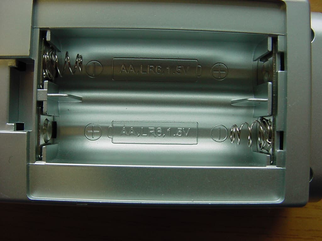
CETECOM ICT Services GmbH Test report no.:5-4812-01-04/04Issue date: 2004-07-05 Page 17 (21) PHOTOGRAPHS OF THE EQUIPMENT Photograph no.: 3 WS738 CETECOM ICT Services GmbH Test report no.:5-4812-01-04/04Issue date: 2004-07-05 Page 18 (21) PHOTOGRAPHS OF THE EQUIPMENT Photograph no.:4 WS738 CETECOM ICT Services GmbH Test report no.:5-4812-01-04/04Issue date: 2004-07-05 Page 19 (21) PHOTOGRAPHS OF THE EQUIPMENT Photograph no.: 5 WS738 CETECOM ICT Services GmbH Test report no.:5-4812-01-04/04Issue date: 2004-07-05 Page 20 (21) PHOTOGRAPHS OF THE EQUIPMENT Photograph no.: 6 WS738 CETECOM ICT Services GmbH Test report no.:5-4812-01-04/04Issue date: 2004-07-05 Page 21 (21) PHOTOGRAPHS OF THE EQUIPMENT Photograph no.: 7 WS738
Test Report
CETECOM ICT Services GmbH Radio Satellite Communication Untertürkheimer Straße 6-10 . D-66117 SaarbrückenTelefon: +49 (0)681 598-9100Telefax: -9075 RSC14issue test report consist of 21 PagesPage 1 (21) Recognized by the Federal Communications Commission Anechoic chamber registration no.: 90462 (FCC) Anechoic chamber registration no.: 3463 (IC) TCB ID: DE 0001 Accredited by the German Accreditation Council DAR–Registration Number TTI–P–G 081/94-D0 Independent ETSI compliance test house ETSI Accredited Bluetooth™ Test Facility (BQTF) Test report no.: 5-4812-01-04/04 Mandolyn Electronic Tech. Inc. FCC Part 15.109 / RSS210 WS738 CETECOM – ICT Services GmbH Untertürkheimerstr. 6-10 66117 Saarbrücken, Germany Telephone: + 49 (0) 681 / 598-0 Fax: + 49 (0) 681 / 598-9075 BLUETOOTH is a trademark owned by Bluetooth SIG, Inc. and licensed to CETECOM CETECOM ICT Services GmbH Test report no.:5-4812-01-04/04Issue date: 2004-07-05 Page 2 (21) Table of contents 1 General information 1.1 Notes 1.2 Testing laboratory 1.3 Details of applicant 1.4 Application details 1.5 Test item 1.6 Test specifications 2 Technical test 2.1 Summary of test results 2.2 Test report CETECOM ICT Services GmbH Test report no.:5-4812-01-04/04Issue date: 2004-07-05 Page 3 (21) 1 General information 1.1 Notes The test results of this test report relate exclusively to the test item specified in 1.5. The CETECOM ICT Services GmbH does not assume responsibility for any conclusions and generalisations drawn from the test results with regard to other specimens or samples of the type of the equipment represented by the test item. The test report may only be reproduced or published in full. Reproduction or publication of extracts from the report requires the prior written approval of the CETECOM ICT Services GmbH. Test laboratory manager: 2004-07-06RSC - 8433Kirsch A. DateSectionNameSignature Technical responsibility for area of testing: 2004-07-06RSC - 8412Hausknecht D. DateSectionNameSignature CETECOM ICT Services GmbH Test report no.:5-4812-01-04/04Issue date: 2004-07-05 Page 4 (21) 1.2 Testing laboratory CETECOM ICT Services GmbH Untertürkheimer Straße 6 - 10 66117 Saarbrücken Germany Telephone: + 49 681 598 - 0 Telefax : + 49 681 598 - 9075 E-mail: [email protected] Internet: www.cetecom-ict.de Accredited testing laboratory Accredited by: Regulierungsbehörde für Telekommunikation und Post (RegTP) Listed by: Federal Communications Commission (FCC) AuthorityIdentification/Registration No. RegTPTTI-P-G 081/94-D0 FCC90462 1.3Details of applicant Name : Mandolyn Electronic Tech. Inc. Street : 250 Shields Court, Unit 10B City : Markham, Ontario L3R 9W7 Country : Canada Telephone : +1-905-305-0923 Telefax : +1-905-305-0924 Contact : Contact person: Name : C.M.Yip Telephone : +1-905-305-0923 Telex : +1-905-305-0924 E-mail : 1.4Application details Date of receipt of test item : 2004-06-30 Date of test: 2004-07-05 Person(s) who have been : -.- present during the test: -.- CETECOM ICT Services GmbH Test report no.:5-4812-01-04/04Issue date: 2004-07-05 Page 5 (21) 1.5Test item Type of equipment : Receiver Type designation:WS738 Manufacturer:See applicant Street: City: Country: Serial number: Additional information : Frequency:433,92 MHz Modulation:AM Channel spacing:-.- Number of channels :1 Antenna:Wire antenna 17cm ERP:- Power supply:3,0 V DC (2*1,5 V AA batteries) Temperature range:-9,9°C to +55°C 1.6Test specifications: FCC Part 15 §15.109 CANADA RSS-210 CETECOM ICT Services GmbH Test report no.:5-4812-01-04/04Issue date: 2004-07-05 Page 6 (21) 2 Technical test 2.1 Summary of test results FCC Part 15 Subpart B The radiated measurements are performed in vertical and horizontal plane in the frequency range from 9 kHz to 20 GHz in semi-anechoic chambers. The EUT is positioned on a non- conductive support with a height of 0.80 m above a conductive ground plane that covers the whole chamber. The receiving antennas are conform with specifications ANSI C63.2-1996 clause 15 and ANSI C63.4-2001 clause 4.1.5. These antennas can be moved over the height range between 1.0 m and 4.0 m in order to search for maximum field strength emitted from EUT. The measurement distances between EUT and receiving antennas are indicated in the test set-ups for the various frequency ranges. For each measurement, the EUT is rotated in all three axes until the maximum field strength is received. The wanted and unwanted emissions are received by spectrum analysers where the detector modes and resolution bandwidths over various frequency ranges are set according to requirement ANSI C63.4-2001 clause 4.2. Antennas are conform with ANSI C63.2-1996 item 15. 150 kHz - 30 MHz: Quasi Peak measurement, 9kHz Bandwidth, passive loop antenna. 30 MHz - 200 MHz: Quasi Peak measurement, 120KHz Bandwidth, biconical antenna 200MHz - 1GHz: Quasi Peak measurement, 120KHz Bandwidth, log periodic antenna >1GHz: Average, RBW 1MHz, VBW 10 Hz, wave guide horn All measurement settings are according to FCC 15.109 and 15.107 The product fulfils also the requirements for CANADA RSS-210 No deviations from the technical specification(s) were ascertained in the course of the tests performed. FINAL VERDICT : PASS CETECOM ICT Services GmbH Test report no.:5-4812-01-04/04Issue date: 2004-07-05 Page 7 (21) 2.2Test report TEST REPORT Test report no: 5-4812-01-04/04 CETECOM ICT Services GmbH Test report no.:5-4812-01-04/04Issue date: 2004-07-05 Page 8 (21) LIST OF MEASUREMENTS. The list of measured parameters is given below. Clause Page number Transmitter parameters § 15.109Spurious radiations – Radiated9 Test equipment listing11 Photographs of the equipment13 CETECOM ICT Services GmbH Test report no.:5-4812-01-04/04Issue date: 2004-07-05 Page 9 (21) REFERENCE NUMBER(S) OF TEST EQUIPMENT USED (for reference numbers see test equipment listing) 17 – 24: 53 , 54 , 62 SPURIOUS RADIATION § 15.209 Radiated RF Power on SPURIOUS EMISSIONS LEVEL (μV/m) WS738 f (MHz) DetectorLevel (μV/m) Limit (μV/m) Margin (dB) R…
Text truncated - open the document above for the full version.
Test Setup Photos
CETECOM ICT Services GmbH Test report no.:5-4812-01-04/04Issue date: 2004-07-05 Page 13 (21) Photographs of the equipment Test site CETECOM ICT Services GmbH Test report no.:5-4812-01-04/04Issue date: 2004-07-05 Page 14 (21) Test site
Contact Information
Applicant
C.M. Yip(Engineering Manager)
Test Firm
Cetecom ICT Services GmbHRalf Hoehn
Technical Specifications
| # | Rule Parts | Frequency Range | Power Output |
|---|---|---|---|
| 1 | 15B | 433.92 MHz - 433.92 MHz | - |
Other Applications from Mandolyn Electronic Technology Inc.
PLJDB910
Jul 03, 2007Wireless Doorbell
Equipment Class
CYY - Communications Receiver used w/Pt 15 Transmitter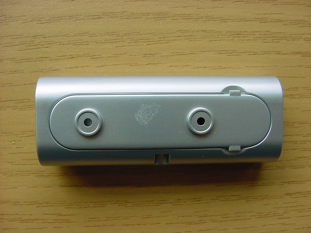
PLJDBT701
Jul 03, 2007Wireless Doorbell
Equipment Class
DSC - Part 15 Security/Remote Control Transmitter
PLJWS2635
Mar 13, 2007Weather Station Receiver
Equipment Class
CRR - Superregenerative Receiver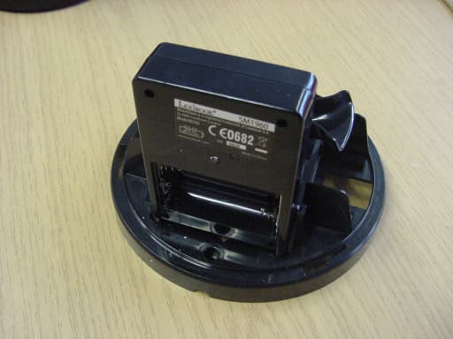
PLJWDS500
Mar 13, 2007Weather Station Transmitter
Equipment Class
DSC - Part 15 Security/Remote Control Transmitter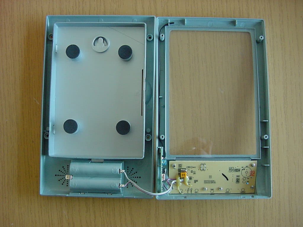
PLJWS1200
Mar 13, 2007Weather Station Receiver
Equipment Class
CRR - Superregenerative Receiver