PMUIV012AVideo Card
InsideTNC Co., Ltd.
Click to zoom
Application Details
- Equipment Class
- JBP - Part 15 Class B Computing Device Peripheral
- Date of Grant
- Jul 04, 2001
- Application Purpose
- Original Equipment
- Date of Application
- Jul 04, 2001
- Equipment Note
- Video Card
- Company
- InsideTNC Co., Ltd.
- Country
- South Korea
Documents & Files
Document Text
Text extracted from the exhibit documents filed with the FCC. Open a document above to read the original.
Users Manual
I I n n s s i i d d e e T T N N C C I I V V 0 0 1 1 2 2 A A U U S S E E R R ’ ’ S S G G U U I I D D E E Copyright© 2000 Inside Teletcom Co.,Ltd. This installation guide is copyrighted. All rights reserved. This document may not, in whole or part, be copied, reproduced, reduced or translated by any means, either mechanical or electronic, without prior consent in writing from Inside Telnetcom Co., Ltd. The information in this manual has been carefully checked and is believed to be accurate. However, Inside Telnetcom Co., Ltd assumes no responsibility for any inaccuracies that may be contained in this manual. In the interest of continuous product development product development, Inside Telnetcom Co., Ltd. reserves the right to make improvements in this manual and the products describes it at any time, without notice obligation. LOCATION OF INSIDE TELNETCOM CO., LTD ADD. : #1138, Sanbon-Dong, Kunpo-City, Kyounggi-Do, Korea., 435-040 TEL. : 82-31-396-1500 FAX. : 82-31-396-1112 URL. : www.insidetnc.co.kr IDREAM.GeForce2 MX/GTS is is registered trademark of Inside Telnetcom Co., Ltd Intel Pentium®III is registered trademark of Intel Inc. Microsoft Windows® is registered trademark of Microsoft Corporation. nVIDIA GeForce2 MX/GTS® is registered trademark of NVIDIA Corporation. All other trademarks belong to their respective owners. Copyright© 1999 Inside Telnetcom Co., Ltd, This product is for home use registered suitable EMI, you can use in the all kinds of area including a residential district. FCC RF INTERFERENCE STATEMENT NOTE : This equipment has been tested and found to comply with the limits for a Class B digital device, pursuant to Part 15 of the FCC Rules. These limits are designed to provide reasonable protection against harmful interference in a residential installation. This equipment generates, uses and can radiate radio frequency energy and, if not installed and used in accordance with the instructions, may cause harmful interference to radio communications. However, there is no guarantee that interference will not occur in a particular installation. If this equipment does cause harmful interference to radio or television reception which can be determined by turning the equipment off and on, the user is encouraged to try to correct the interference by one or more of the following measures. - Reorient or relocate the receiving antenna. - Increase the separation between the equipment and receiver. - Connect the equipment into an outlet on a circuit different from that to which the receiver is connected. - Consult the dealer or an experienced radio, TV technical for help. - Only shielded interface cable should be used. Finally, any changes or modifications to the equipment by the user not expressly approved by the grantee or manufacturer could void the users authority to operate such equipment, - CONTENTS - 1. Features of InsideTNC’s IV012A ...................................................... - The Feature of GeForce2 MX/GTS - System Requirement - Driver and Software Support 2. Installation (Hardware) ........................................................................ 3. Installation (Software) ........................................................................... Method I. Plug& Play .................................................................................... Method II. Do it your self .............................................................................. 4. Troubleshooting ................................................................................. APPENDIX * Table 1-1. Windows 95/98ME Resolution rate & Refresh rate- 32MB * Table 1-2. Windows 95/98 ME 3D Display Mode - 32MB 1. The Feature of InsideTNC’s IV011A Used nVIDIA’s GeForce2 MX/GTS GPU, Inside Telnetcom’s IV011A supports the advanced features, TwinView, a innovative dual display architecture, which doubles your desktop workspace using two space saving display and. DVC(Digital Vibrance Control) which provides crisp, bright visuals. IV011A(DREAM.GeForce2 GTS) supports second Transform and Lighting Engines, NSR to be able to bring natural material properties to life via seven simultaneous pixel operations that deliver advanced per –pixel shading capabilities in a single pass and HDVP(High –Definition Video Processor) to enable you to turn their PCs into full quality DVD players and HDTV receivers/players. The Feature of GeForce2 MX / GTS nVIDIA Corporation’s GeForce2 MX/GTS GPU Core ClockMemory Clock GeForce2 MX200 MHz166 MHz GeForce2 GTS200 MHz333 MHz SDRAM 32MB / 64MB NVIDIA Shading Rasterizer(NSR) High-Definition Video Processor (HDVP) Per-Pixel Shading and Advanced Video Processing Microsoft® Direct® and OpenGL® Optimization and Support TV-Out Support: Composite, S-VHS – option TwinView : TwinView is NVIDIA's innovative dual display architecture. Through TwinView, IV011A supports the widest range of dual display configurations on the planet. You can connect virtually any combination of TVs, flat panels, and monitors. IV011A with TwinView is the first device to support two digital flat panel displays through dual integrated TMDS transmitters. (www.nvidia.com) DVC(Digital Vibrance Control) : It's rare to find ideal lighting conditions for crisp, bright, clean onscreen visuals at home or in the office. Digital Vibrance Control is a patent pending innovation that allows the user to digitally control the intensity of all images through a simple control panel. The result is richer color, and brighter, cleaner, more ergonomically pleasing images. (www.nvidia.com) NVIDIA Shading Rasterizer(NSR) : With the NVIDIA Shading Rasterizer (NSR) in GeForce2 GTS, wood looks grainy, lit objects gleam in the hotspots yet also cast realistic shadows, and water ripples and rolls into waves. (www.nvidia.com) System Requirements - Intel Pentium II 233MHz (Minimum) or compatible CPU - Windows 95(OSR 2.1 Minimum) / Windows98 / Windows 98SE / Windows ME - Windows NT 4.0 with Service pack 3 minimum)/ Windows20…
Text truncated - open the document above for the full version.
Users Manual
2. After Selecting Search for the best driver for your device(Recommended) from the following dialogue box, insert the Support CD into your CD-ROM drive. From the Specify the Location:, select E:\VGA\DRIVER\GeForce2 MX/GTS\Win9X , click Next. In this case, E:\ means CD-ROM drive. 3.Select The updated software [Recommended] InsideTNC GeForce2 MX/GTS and click Next. 4. When Windows driver file search for the device: InsdieTNC GeForce2 MX/GTS appears, click Next. 5. Copying files to Windows system folder should been completed. It may take a few seconds. 6. Click Finish to complete setup. 7. Click Yes to restart your computer. Method II. Do It Yourself 1. In order to install the driver of Inside’s GeForce2 MX/GTS by yourself, Select Start > Setting > Control Panel > System Properties > Device manager > Display adapters > Standard PCI Graphics Adapters and click Properties in Windows95/98/ME. 2. From Standard PCI Graphics Adapter [VGA] Properties > Driver, click Update Driver... 3. Select Specify the location of the driver [Advanced] and click Next. 4. From the select Search for a better driver than the one your device is using now. [Recommended] and then check the Specify a location E:\\VGA\DRIVER\GeForce2 MX/GTS\Win9X. and then click Next. In this case, E: \ means CD-Rom drive. 5. When Windows driver file search for the device: InsdieTNC GeForce2 MX/GTS appears, click Next. 6. Copying files to Windows system folder should been completed. It may take a few seconds. 7. Click Finish to complete setup. 8. . Click Yes to restart your computer. 4. Troubleshooting The graphic board users queried as follow: Question 1 : ‘Version Crash’ message appeared and Windows asked me “Do you save ex-file?” during installing driver. How can I answer to solve it? Answer 1 : When we change the graphic board, the same file name exists in the System folder in Windows. . In this case, selecting No is recommended. Question 2 : Even driver installation was completed, 16 color was selected only. When you select 256color at a minimum refresh rate, computer was restarted and the message refresh rate was not fix to the system appears on the screen. Answer 2 : It’s the error message when the system files crashed each others or compulsory driver installation was done. In this case, from Control Panel > System > Device Control > Display Adapter, selected Device Driver should he selected to Standard Display Adapter and then reinstall Driver. Then, you can select 256 Color to 16bit High Color and 32bit True Color. Question 3 : Even my monitor size is 17inch, I can not select over 800◊600 (Resolution Rate) from a display setting. Answer 3 : You can change the driver with Support Driver Disk which you got from Monitor Producer when you bought it or you can select ‘plug & play monitor’ then you can use the maximum of Resolution Rate. See Appendix- Table 1-1 , for the a list of compatible resolutions. Question 4 : My monitor is either blank, or the display image is distorted or scrambled. Answer 4 : It’s caused by the low refresh rate. Select to the maximum refresh rate supported by the monitor. Question 5 : As you play games, the screen turns to Windows immediately . Answer 5 : It depends on the game. Upgrade the DirectX to the newest version or install the patch file that the game producers give, and then you can play game. Question 6 : Playing 3D games causes system down. Answer 6 : Check the heat condition CPU or reinstall the Windows. APPENDIX *Table 1-1. Windows 95/98ME Resolution Rate & Refresh Rate- 32MB Refresh Rate Resolution Rate 25665K16M 640*480 60, 72, 75, 85, 100, 120, 170, 200Hz 60, 72, 75, 85, 100, 120, 170, 200Hz 60, 72, 75, 85, 100, 120, 170, 200Hz 800*60060, 72, 75, 85, 100, 120Hz60, 72, 75, 85, 100, 120Hz60, 72, 75, 85, 100, 120Hz 1024*76860, 72, 75, 85, 100, 120Hz60, 72, 75, 85, 100, 120Hz60, 72, 75, 85, 100, 120Hz 1152*86460, 72, 75, 85, 100, 120Hz60, 72, 75, 85, 100, 120Hz60, 72, 75, 85, 100, 120Hz 1280*102460, 72, 75, 85, 100, 120Hz60, 72, 75, 85, 100, 120Hz60, 72, 75, 85, 100Hz 1600*120060, 72, 75, 85Hz60, 72, 75, 85Hz60, 72, 75Hz * Table 1-2. Windows 95/98 ME 3D Display Mode - 32MB Resolution Rate Double – BufferDouble – Buffer + Z-Buffer 640*48016, 3216, 32 800*60016, 3216, 32 1024*76816, 3216, 32 1152*86416, 3216, 32 1280*102416, 3216, 32 1600*120016, 3216, 32
Block Diagram
VGA FEATURE CONNECTOR CRYSTAL 14.31818MHZ GeForce2 ULTRA GRAPHICS ACCELERATOR VGA / DDC CONNECTOR VOLTAGE REGULATOR +2.05V GRAPHICS MEMORY DDR SDRAM 64MB BIOS ROM AGP CONNECTOR BLOCK DIAGRAM AGP STANDARD CNTL ADDP / DATA CNTL ADDR DATA ADDR / DATA
ID Label/Location Info
ID Label Sample THIS DEVICE COMPLIES WITH PART 15 OF THE FCC RULES. OPERATION IS SUBJECT TO THE FOLLOWING TWO CONDITIONS: (1)THIS DEVICE MAY NOT CAUSE HARMFUL INTERFERENCE, AND (2)THIS DEVICE MUST ACCEPT ANY INTERFERENCE RECEIVED, INCLUDING INTERFERENCE THAT MAY CAUSE UNDESIRED OPERATION. FCC ID : PMUIV012A MADE IN KOREA
ID Label/Location Info
Label Location Information THIS DEVICE COMPLIES WITH PART 15 OF THE FCC RULES. OPERATION IS SUBJECT TO THE FOLLOWING TWO CONDITIONS: (1)THIS DEVICE MAY NOT CAUSE HARMFUL INTERFERENCE, AND (2)THIS DEVICE MUST ACCEPT ANY INTERFERENCE RECEIVED, INCLUDING INTERFERENCE THAT MAY CAUSE UNDESIRED OPERATION. FCC ID : PMUIV012A MADE IN KOREA
Test Report
File No. 01-IST-049/FB IST EMC LAB. Page 1 of 13 IST EMC Lab. San 21-8 Goan-Ri, Baekam-Myun, Yongin-Si, Kyunggi-Do, KOREA International - Tel : 82-31 - 333 - 4093. Fax : 82-31 - 333 - 4094. Domestic - Tel : 031 - 333 - 4093. Fax : 031 - 333 - 4094. IST EMC LAB. EMISSION TEST REPORT Test report file No. : 01-IST-049/FB Date of issue : Apr. 20, 2001. Model / Type No. Kind of product Applicant Manufacturer Address : IV012A : VGA Card : Inside Telnetcom Co., Ltd. : Inside Telnetcom Co., Ltd. : Rm.608 Kum-Gang Venturetel Bldg,#1108,Bi-San Dong, Dong-An Gu, An-Yang City, Kyung-Gi Do,431-050, KOREA Test result according to the regulation(s) n Positive o Negative at page 3. This test report without appendix consists of 13 pages. It is not allowed to copy this report even partly without the allowance of the Test Laboratory. This equipment is complied with the applicable technical standards as indicated in the measurement report and was tested in accordance with the measurement procedures specified in ANSI C63.4-1992. File No. 01-IST-049/FB IST EMC LAB. Page 2 of 13 IST EMC Lab. San 21-8 Goan-Ri, Baekam-Myun, Yongin-Si, Kyunggi-Do, KOREA International - Tel : 82-31 - 333 - 4093. Fax : 82-31 - 333 - 4094. Domestic - Tel : 031 - 333 - 4093. Fax : 031 - 333 - 4094. DIRECTORY A) Documentation. Page Directory Test regulations Environmental Conditions Test Conditions Equipment under Test Test Result Test-setup (Figures) Summary 2 3 3 4~5 6 7 8 13 B) Test Data. Conducted emissions (Mains) Radiated emissions : 450 kHz - 30 MHz : 30 MHz – 1 GHz 9 ~ 11 12 C) Appendix File No. 01-IST-049/FB IST EMC LAB. Page 3 of 13 IST EMC Lab. San 21-8 Goan-Ri, Baekam-Myun, Yongin-Si, Kyunggi-Do, KOREA International - Tel : 82-31 - 333 - 4093. Fax : 82-31 - 333 - 4094. Domestic - Tel : 031 - 333 - 4093. Fax : 031 - 333 - 4094. TEST REGULATIONS The tests were performed according to the following regulations ; z - FCC Part 15, Subpart B (Unintentional Radiators, Class B) Information of Test Laboratory IST EMC Lab. San 21-8 Goan-Ri, Baekam-Myun, Yongin-Si, Kyunggi-Do, Korea International - Tel : 82-31 - 333 - 4093. Fax : 82-31 - 333 - 4094. Domestic - Tel : 031 - 333 - 4093. Fax : 031 - 333 - 4094. Product Information - Power rating : 100~240 Vac, 50/60 Hz / DC 2.0V, 5V, 3.3V, 12V, 1.6V (Insert to PC) - Brand name : Inside Telnetcom - Manufactured by : Inside Telnetcom CO.,Ltd. - Contact person : Mun-Sang Lim / R&D General Manager ENVIRONMENTAL CONDITIONS Temperature Humidity Atmospheric pressure 23 42 % 1000 mbar File No. 01-IST-049/FB IST EMC LAB. Page 4 of 13 IST EMC Lab. San 21-8 Goan-Ri, Baekam-Myun, Yongin-Si, Kyunggi-Do, KOREA International - Tel : 82-31 - 333 - 4093. Fax : 82-31 - 333 - 4094. Domestic - Tel : 031 - 333 - 4093. Fax : 031 - 333 - 4094. TEST CONDITIONS The measurement of the conducted emissions (Interference voltage) was performed in a shielded room. Test location : z - Shielded room. No.1 - Compact chamber 2 Used testing instruments : NameTypeManufacturerCalibration. DateSerial Number z ESH 3Test ReceiverRohde & SchwarzOct. 08, 2000861742/018 z 3725/2LISNEMCOOct. 08, 20009102-1788 z 3825/2LISNEMCODec. 20, 20009103-1788 z ESH 3-Z2Pulse LimiterRohde & SchwarzJun. 16, 2001357.8810.52 Test - accessories : Type Manufacturer z Aneroid BarometerSato z HygrometerSato Measurement Procedures : Conducted emissions measurments were made in accordance with ANSI C-63.4-1992,“Method of Measurement of Radio-Noise Emissions from Low-Voltage Electrical and Electronic Equipment in the Range of 9 kHz to 40 GHz”. The measurement were performed over the frequency range of 0.45MHz to 30MHz using a 50Ω/ 50uH LISN as the input transducer to an EMI/Field Intensity Meter. The measurements were made with the detector set for “Peak” amplitude within an IF bandwidth of 10kHz or for “quasi-peak” within a bandwidth of 9kHz. All used test-instruments as well as the test-accessories are calibrated regularly. Test engineer : B. K, Bae. / Research Engineer IST EMC Lab. File No. 01-IST-049/FB IST EMC LAB. Page 5 of 13 IST EMC Lab. San 21-8 Goan-Ri, Baekam-Myun, Yongin-Si, Kyunggi-Do, KOREA International - Tel : 82-31 - 333 - 4093. Fax : 82-31 - 333 - 4094. Domestic - Tel : 031 - 333 - 4093. Fax : 031 - 333 - 4094. The measurement of the radiated emissions (Electric field) in the frequency range from 30 MHz to 1GHz was performed in horizontal and vertical antenna polarization at a open-site which meet the site attenuation requirement of ANSI C63.4-1992 and a test distance of : z - Open-site 1 - Compact chamber z - 3 meters - 10 meters Used testing instruments : NameTypeManufacturerCalibration. DateSerial Number z ESVPTest ReceiverRohde & Schwarz July. 21, 2000 861744/004 z VULB 9160AntennaSchwarzbeckJuly. 11, 20003048 Test - accessories : TypeManufacturer z Aneroid BarometerSato z HygrometerSato Measurement procedures Radiated measurements were in accordance with ANSI C63.4-1992 “Method of Measurement of Radio- Noise Emissions from Low-Voltage Electrical and Electronic Equipment in the Range of 9 kHz to 40 GHz”. The measurements were performed over the frequency range of 30MHz to 1GHz using antenna as the input transducer to a EMI/Field Intensity Meter. The measurements were made with the detector set for “quasi-peak” within a bandwidth of 120kHz. All used test-instruments as well as the test-accessories are calibrated regularly. Test engineer : B. K, Bae. / Research Engineer IST EMC Lab. File No. 01-IST-049/FB IST EMC LAB. Page 6 of 13 IST EMC Lab. San 21-8 Goan-Ri, Baekam-Myun, Yongin-Si, Kyunggi-Do, KOREA International - Tel : 82-31 - 333 - 4093. Fax : 82-31 - 333 - 4094. Domestic - Tel : 031 - 333 - 4093. Fax : 031 - 333 - 4094. EQUIPMENT UNDER TEST Equipment Description The Equipment Under Test (EUT) is the VGA Card of Inside Telnetcom Co., Ltd. Picture Tube- Type: VGA Card (3D) - CPU : GeForce2 ULTRA(nVIDIA) Video- Input Signal: Analog R,G,B & Digital Mode - T&L(Transform&Lighting) - TV Out : Composite, S-VHS (Option), HDTV&DVD Re…
Text truncated - open the document above for the full version.
Test Setup Photos
Radiated Emission 30MHz ~ 1000MHz Conducted Emission 450kHz ~ 30MHz
Contact Information
Applicant
Kyung-Sik Jeon(Manager)
Test Firm
IST Co., LtdBong Kyoon Bae
Technical Specifications
| # | Rule Parts | Frequency Range | Power Output |
|---|---|---|---|
| 1 | 15B | - | - |
Other Applications from InsideTNC Co., Ltd.
PMUMP100TX
Mar 29, 2004Magic Presenter Transmitter
Equipment Class
DSC - Part 15 Security/Remote Control Transmitter
PMUMP100RX
Mar 29, 2004Magic Presenter
Equipment Class
CYY - Communications Receiver used w/Pt 15 Transmitter
PMUIV029A
Jan 31, 2002Video Card
Equipment Class
JBP - Part 15 Class B Computing Device Peripheral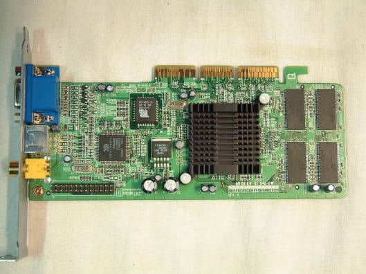
PMUIV014A
Aug 21, 2001Video Card
Equipment Class
JBP - Part 15 Class B Computing Device Peripheral
PMUIV001AS
Jul 11, 2001Video Card
Equipment Class
JBP - Part 15 Class B Computing Device Peripheral