PMUIV029AVideo Card
InsideTNC Co., Ltd.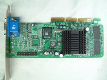
Click to zoom
Application Details
- Equipment Class
- JBP - Part 15 Class B Computing Device Peripheral
- Date of Grant
- Jan 31, 2002
- Application Purpose
- Original Equipment
- Date of Application
- Jan 31, 2002
- Equipment Note
- Video Card
- Company
- InsideTNC Co., Ltd.
- Country
- South Korea
Documents & Files
Document Text
Text extracted from the exhibit documents filed with the FCC. Open a document above to read the original.
Users Manual
TABLE OF CONTENTS 1. Hardware Installation 2. Drive Installation A. Windows 95 / 98 / ME B. Windows 2000 / XP 3. TV-OUT Function Instruction 4. Digital LCD Monitor (DVI-OUT) 5. FAQ System Requirements - Intel Pentium III 350MHz or higher version CPU (Intel Pentium IIII, Intel Celeron, AMD Athlon, AMD Duron...) - Windows 98 / ME, Windows 2000 / XP, - Any Motherboard with AGP 2.0 or higher - CDROM & Mouse required Warning Before you install Hardware, you must make sure that the computer plug is off for your safety from a sudden electricity impulse. 1 1 . . H H a a r r d d w w a a r r e e I I n n s s t t a a l l l l a a t t i i o o n n 1. Turn off your compute, remove the computer case, and check out the location of AGP Slot. AGP Slot (Brown color) is placed in the middle of M/B. 2. Remove your old graphics card, and install your new Graphic cards. Caution!! AGP Slot’s connection part is different with general PCI. It is double structured. You must make sure that the card is placed to the end. If the card is not placed in the slot, the system will not be working at all. 3. Align and secure the mounting bracket of the card to the computer and replace the computer case. Connect the monitor cable to graphic card connector. 4. Turn on your computer and follow up the instruction to install software. 2 2 . . D D r r i i v v e e i i n n s s t t a a l l l l a a t t i i o o n n A. Windows 95 / 98 / ME B. Windows 2000 / XP 3 3 . . T T V V - - O O U U T T F F u u n n c c t t i i o o n n I I n n s s t t r r u u c c t t i i o o n n s s 4 4 . . D D i i g g i i t t a a l l F F l l a a t t P P a a n n e e l l I I n n s s t t r r u u c c t t i i o o n n s s ( ( D D V V I I - - O O U U T T ) ) FCC Requirement This device has been certified to comply with the limits for a Class B computing device pursuant to Subpart J of Part 15 of the FCC Rules. See instructions if interference to radio reception is suspected. WARNING: This equipment generates and uses radio frequency energy and, if not installed or used properly, that is, in strict accordance with the manufacturer's instructions, may cause interference to radio or television reception. It has been tested and found to comply with the limits for a Class B compliant device in accordance with the specifications in Subpart J of Part 15 of FCC Rules, which are designed to provide reasonable protection against such interference in a residential installation. However, there is no guarantee that interference-will not occur in a particular installation. If this equipment does cause interference to radio or television reception, which can be determined by turning the equipment off and on, the user is encouraged to try to correct the interference by one or more of the following measures: Reorient the receiving antenna Relocate the computer away from the receiver Move the computer away from the receiver Plug the computer into a different outlet so that the computer and the receiver are on different branch circuits Ensure that the card's mounting screws, attachment connector screws, and ground wires are tightly secured Ensure that slot covers are installed in all unused slots If necessary, consult your dealer, service representative, or an experienced radio/television Technician for additional suggestions. The manufacturer is not responsible for any radio or TV interference caused by unauthorized modifications to this equipment. It is the responsibility of the user to correct such interference. The user may find the following booklet prepared by the Federal Communications Commission helpful: How to Identify and Resolve Radio-TV Interference Problems. This booklet is available from the Government Printing Office, Washington, D.C. 20402, Stock No. 004-000-00345-4. NOTE: You must use shielded interface cables with a ferrite bead in order to maintain compliance with the limits for a Class B device. CAUTION: CHANGES OR MODIFICATIONS NOT EXPRESSLY APPROVED BY THE PARTY RESPONSIBLE FOR COMPLIANCE COULD VOID THE USER'S AUTHORITY TO OPERATE THE EQUIPMENT Notice The information in this document is subject to change in order to improve reliability, design, or function without prior notice and does not represent a commitment on the part of this company. In no event will we be liable for direct, indirect, special, incidental, or consequential damages arising out of the use or the inability to use the product or documentation, even if advised of the possibility of such damages. No part of this reference manual may be reproduced or transmitted in any form or by any means without the prior written permission of this company. 2000 Trademark Acknowledgements All brand names and trademarks are the property of their owners. Limited Warranty Our company warrants this product against defects in materials and workmanship for a period of three (3) year from the date of purchase. During the warranty period, a product determined by us to be defective in form or function will be repaired or at our option, to be replaced at no charge. This warranty does not apply if the product has been damaged by accident, abuse, misuse, or as a result of service or modification other than by us. This warranty is in lieu of any other warranty expressed or implied. In no event shall we be held liable for incidental or consequential damages, such as lost revenue or lost business opportunities arising from the purchase of a this product.
Block Diagram
CRYSTAL 14.31818MHZ GeForce2 MX200 GRAPHICS ACCELERATOR VGA CONNECTOR VOLTAGE REGULATOR +2.0V GRAPHICS MEMORY SDRAM 32M BIOS ROM AGP CONNECTOR BLOCK DIAGRAM AGP STANDARD CNTL ADDP / DATA CNTL ADDR DATA ADDR / DATA VGA FEATURE CONNECTOR
External Photos
Test report Our reference : KEL02-F01018 Page : B1 of Appendix Issued date : 2002-01-21 Appendix-B : External Photographs of E.U.T <FRONT VIEW OF EUT> <REAR VIEW OF EUT>
ID Label/Location Info
Test report Our reference : KEL02-F01018 Page : D1 of Appendix Issued date : 2002-01-21 Appendix-D : FCC ID label location information and Sample - FCC ID label location information The label included following statement will be attached on the rear side of product. - FCC ID label sample
Internal Photos
Test report Our reference : KEL02-F01018 Page : C1 of Appendix Issued date : 2002-01-21 Appendix-C : Internal Photographs of E.U.T <INTERNAL VIEW OF E.U.T> Test report Our reference : KEL02-F01018 Page : C2 of Appendix Issued date : 2002-01-21 <FRONT VIEW OF MAIN BOARD> Test report Our reference : KEL02-F01018 Page : C3 of Appendix Issued date : 2002-01-21 <REAR VIEW OF MAIN BOARD>
Test Report
CERTIFICATE OF COMPLIANCE CERTIFICATE OF COMPLIANCECERTIFICATE OF COMPLIANCE CERTIFICATE OF COMPLIANCE 352 Youngduk-Ri, Kihung-Eup, Yongin-City, Kyunggi-Do, Korea 449-908 TEL : (82)31-206-4693 FAX : (82)31-206-3051 htt p:/ / www.ke sila b.co m we bmaste r@ke silab.co m http://www.koreaemc.co.kr [email protected] (CLASS B) CERTIFICATION O F COMPLIANCE is he re by issue d to t he name d Applicant and is VALID ONLY for t he equipment identified below: Date of Tested : Jan. 17. 2002 Applicant’s Name : INSIDE TELNETCOM CO. LTD. Appl i c a nt ’ s Ad dr e ss : Rm.608-610,Kum-Gang Venturetel Bldg,#1108,Bisan Dong Dongan Gu, Anyang City Kyunggi-Do, Korea Manufacturer’s Name : INSIDE TELNETCOM CO. LTD. Manufacturer’s Address : Rm.608-610,Kum-Gang Venturetel Bldg,#1108,Bisan Dong Dongan Gu, Anyang City Kyunggi-Do, Korea Declares that the product Product Description : Video Card Brand Name : INSIDE TELNETCOM M o de l Numbe r : IV029A FCC ID : PMUIV029A Conforms to FCC Rules and Regulations Part 15 Subpart B requirements. This product herewith complies with the requirements of the FCC Rules and Regulations as listed below: Part 15.107: Conducted Emissions. Part 15.109: Radiated Spurious Emissions. TESTED and CERTIFIED by: KOREA EMC LABORATORY 352 Youngduk-Ri, Kihung-Eup, Yongin-Si, Kyunggi-Do, 449-908, KOREA Date : Jan. 21. 2002 Report No : KEL02-F01018 Authorized Signature : M. S. CHO / President TABLE OF CONTENTS Test report Our reference : KEL02-F01018 Page : 2 of 13 Issued date : 2002-01-21 Korea EMC Laboratory DESCRIPTION Page 0. VERIFICATION OF COMPLIANCE 3 1. GENERAL INFORMATION 1.1 Product Description 4 1.2 Related Submittal(s)/Grant(s)4 1.3 Tested System Details4 1.4 System Configuration 4 1.5 General Setup of the test Shield room5 1.6 Test Facility5 2. Measurement Procedure 2.1 System test configuration6 2.1.1 Video mode Justification6 2.1.2 EUT Exercise S/W 6 2.2 Special Accessories6 2.3 Equipment Modification6 2.4 System Configuration Diagram6 2.5 Preliminary testing7 2.6 Shielded Enclosure7 2.7 Data Reporting Format7 2.8 Operating Condition7 2.9 Conditioning of the EUT7 2.10 Power Line Conducted Emissions8 2.11 Open field Radiated Emissions Tests8 3. Measurement Data 3.1 Conducted Emission Data9 3.2 Conducted Emission Graph10 3.3 Radiated Emission Data11 3.4 Summary 12 4. Labeling Requirement13 Appendix - A : Test set-up Photographs (Conducted and Radiated) - B : External Photographs of E.U.T - C : Internal Photographs of E.U.T - D : FCC ID label location information and sample - E : Block Diagram - F : User’s Manual Test report Our reference : KEL02-F01018 Page : 3 of 13 Issued date : 2002-01-21 Korea EMC Laboratory 0 . VERIFICATION OF COMPLIANCE Equipment Under Test : Video Card Mo d e l N u mb e r : IV029A Serial Number : Prototype Manufacturer : INSIDE TELNETCOM CO. LTD. Rm.608-610,Kum-Gang Venturetel Bldg,#1108,Bisan Dong Dongan Gu, Anyang City Kyunggi o, Korea Type of Test : FCC CLASS B Report Number : KEL02-F01018 Date Tested : Jan. 17. 2002 Tested By : H. S. CHOI The results show that the sample equipment tested as described in this reports is in compliance with the CLASS B conducted and radiated emission limits of FCC Rules Part 15, Subpart B. Test report Our reference : KEL02-F01018 Page : 4 of 13 Issued date : 2002-01-21 Korea EMC Laboratory 1. GENERAL INFORMATION 1.1 PRODUCT DESCRIPTION T he IV029A i s a Video Card ma d e b y IN S ID E T ELN ET C O M C O . LT D . i n Ko r e a . Re f e r t o t he u s e r ' s ma nu a l f o r more information. 1.2 Related Submittal(s)/Grant(s) N/A 1.3 Tested System Details TypeModel NameFCC IDSerial NOManufacturer Video CardIV029A PMUIV029APrototype INSIDE TELNETCOM CO. LTD. PCCT6480DoCNONEDAEWOO MonitorG790GSS19001M885200416ViewSonic Corp. KeyboardSKR-1032GJJSKR-10321EAC000237SEJIN MouseSMB-601GJJB50PAQ8KBE020496SEJIN 1.4 System Configuration TypeModel NameSerial NOManufacturerRemark Video CardIV029ANONE INSIDE TELNETCOM CO. LT D . . KOREA Test report Our reference : KEL02-F01018 Page : 5 of 13 Issued date : 2002-01-21 Korea EMC Laboratory 1.5 General Set-up of the Test Shielded Room The EUT was set up in accordance with the suggested configuration given in FCC measurement Procedure ANSI C63.4, 1992. The measurement are performed in the shielded room which dimension is 3.0*7.0*2.5 (m). The EUT was placed on a non conductive table which is 1.0*1.5 (m), 80 cm above an earthed ground plane and is kept at least 1m from any other earthed ground plane except the rear of table top being removed 40cm from a vertical conducting plane. Power to the EUT was provided through the LISN(3725/2,EMCO) which has the Impedance vs Frequency Characteristic in accordance with the Fig.1 Impedance Characteristic of LISN. Peripheral equipment required to provide a functional system(support equipment) for EUT testing was powered through another LISN(NSLK8128,Schwarzbeck). Power to the LISN was filtered to eliminate ambient signal interference. A coaxial type connector which provides a 50 Ohm terminating impedance was provided for the test instrument. The excess length of the power cord was wrapped in the two non metallic pegs attached to the top of the LISN. The two pegs are 9 cm high, approximately 2.0 cm in diameter and that are spaced 6 cm on the center apart. 1.6 Test Facility Location: Korea EMC Laboratory 352 Yungduck-Ri Kihung-Eup,Yongin-City Kyungki-Do,Korea Site : - 3/10 m Open Fielded Radiated - Indoor Line Conducted Room(Shielded) The Open Field Radiated and Indoor Line Conducted sites are constructed and calibrated to meet the FCC requirements in documents ANSI C63.4 1992. Korea EMC Lab. was refiled in FCC in Feb. 2001. INSTRUMENTATION DescriptionModelManufacturerSerial NoDue Cal. TEST RECEIVER SPECTRUM ANALYZER ESVS10 ESH-2 ESPC 8566B Rohde & Schwarz Rohde & Schwarz Rohde & Schwarz He wlett-P ac kar d 825120/006 893268/004 844006/038 2421A00473 '2002.10.09 '2002.06.15 '2002.05.29 '2003.03.19 BICONICAL LOG-PERIODIC BI- LOG BICONICAL LOG-PERIODIC VHA91…
Text truncated - open the document above for the full version.
Test Setup Photos
Test report Our reference : KEL02-F01018 Page : A1 of Appendix Issued date : 2002-01-21 Appendix-A : Test Setup Photographs - Conducted Setup Photographs LINE CONDUCTED SETUP PHOTOGRAPH - FRONT VIEW LINE CONDUCTED SETUP PHOTOGRAPH - REAR VIEW Test report Our reference : KEL02-F01018 Page : A2 of Appendix Issued date : 2002-01-21 - Radiated Setup Photograph RADIATED EMISSION SETUP PHOTOGRAPH - FRONT VIEW ( 30 - 300 MHz ) RADIATED EMISSION SETUP PHOTOGRAPH - REAR VIEW ( 30 - 300 MHz ) Test report Our reference : KEL02-F01018 Page : A3 of Appendix Issued date : 2002-01-21 RADIATED EMISSION SETUP PHOTOGRAPH - FRONT VIEW ( 300- 1000 MHz ) RADIATED EMISSION SETUP PHOTOGRAPH - REAR VIEW ( 300 - 1000 MHz )
Contact Information
Applicant
Kyung-Sik Jeon(Manager)
Test Firm
Korea EMC Laboratory Co., LtdMan-sung Cho
Technical Specifications
| # | Rule Parts | Frequency Range | Power Output |
|---|---|---|---|
| 1 | 15B | - | - |
Other Applications from InsideTNC Co., Ltd.
PMUMP100TX
Mar 29, 2004Magic Presenter Transmitter
Equipment Class
DSC - Part 15 Security/Remote Control Transmitter
PMUMP100RX
Mar 29, 2004Magic Presenter
Equipment Class
CYY - Communications Receiver used w/Pt 15 Transmitter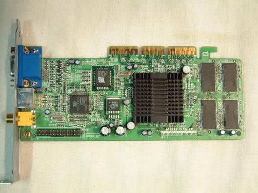
PMUIV014A
Aug 21, 2001Video Card
Equipment Class
JBP - Part 15 Class B Computing Device Peripheral
PMUIV001AS
Jul 11, 2001Video Card
Equipment Class
JBP - Part 15 Class B Computing Device Peripheral
PMUIV012A
Jul 04, 2001Video Card
Equipment Class
JBP - Part 15 Class B Computing Device Peripheral