POSEF-622588MHz-108MHz FM Transmitter
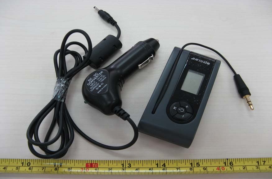
Procare International Co.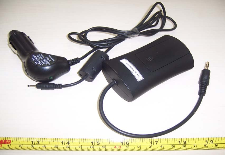
Click to zoom
Application Details
- Equipment Class
- DXX - Part 15 Low Power Communication Device Transmitter
- Date of Grant
- Mar 10, 2007
- Application Purpose
- Original Equipment
- Date of Application
- Mar 10, 2007
- Equipment Note
- 88MHz-108MHz FM Transmitter
- Frequency Range
- 88.10000000 - 107.90000000
- Company
- Procare International Co.
- Country
- Taiwan
Documents & Files
Document Text
Text extracted from the exhibit documents filed with the FCC. Open a document above to read the original.
Users Manual
Product Introduction EF—6225 LCD FM transmitter, a high quality product that adopted advanced PLL technology, stable frequency, crisp sound, has 198 transmitting channel. Unique streamline appearance, smart, user-friendly. When you travel outside or stay at home with it, beautiful music will always surround you, with royal enjoyment. Function Introduction 1、 Searching-channel Function, The button UP and DOWN, searching and fixing available transmitting channel between 88.1~107.9MH Z; 2、 E-switch Function, with delayed function of starting or shutting after a second. 3、 Lighting-indication Function, the LED will shut off automatically after a few seconds to save energy. 4、 Alternative function: switchable automatically between battery and car power,(EF-6211 can only be powered by car charger) 5、 Memory Function, when restarting, the unit can memorize your last channel used before. Technical Parameter 1、 Working Conditions: Environment Temperature:-5~+45°C, 2、Major technical Specs: Working Voltage:3V; Working Current:50mA±5mA; Working Channel:88.1~107.9MH Z Receiving Distance:About 5 meters Installation Instruction and Caution 1、 Insert 2 AAA batteries, or connect the unit to the car charger power(3V), pay attention to the right direction of +"“-"pole. If you want to change the power from battery to car power, please shut off the unit`s power firstly. 2、 Please insert the audio connector directly to the audio output or earphone jack. 3、 Please take out the batteries if not using the unit for long time. 4、 Avoid high temperature, humidity and dust, and avoid using chemical solution to clean the unit, please clean it with soft-wet wipe. Operation Instruction: 1、 Insert 2AAA batteries or connect to its DC jack with a 3V car adaptor from car power. 2、 Insert the audio connector into the audio output or earphone jack of MP3、CD、MD、IPOD player. 3、 Press the power button 1 second to start it. 4、 Press the searching channel button“↑”or“↓”to search your favorite channel. If you keep on pressing the button, the channel will skip fast. 5、 “88.1 When the channel indicates “88.1 MH Z ”, if you press the button “↓”,it will skip to“107.9MH Z ”.but the channel will not be stable untill a few seconds, and vice versa. 6、 When you fix a channel, turn on your MP3、CD、MD、IPOD player, and then tune your radio channel to match the channel of the unit, you will hear the music played from your player. 7、 If you hear noisy or unclear sound from radio, please switch the channel to another one, which had better is not occupied by the local station. Warning: Changes or modifications to this unit not expressly approved by the party responsible for compliance could void the user’s authority to operate the equipment. Note: This equipment has been tested and found to comply with the limits for a Class B digital device, pursuant to part 15 of the FCC Rules. These limits are designed to provide reasonable protection against harmful interference in a residential installation. This equipment generates, uses and can radiate radio frequency energy and, if not installed and used in accordance with the instructions, may cause harmful interference to radio communications. However, there is no guarantee that interference will not occur in a particular installation. If this equipment does cause harmful interference to radio or television reception, which can be determined by turning the equipment off and on, the user is encouraged to try to correct the interference by one or more of the following measures: —Reorient or relocate the receiving antenna. —Increase the separation between the equipment and receiver. —Connect the equipment into an outlet on a circuit different from that to which the receiver is connected. —Consult the dealer or an experienced radio/TV technician for help. This device complies with Part 15 of the FCC Rules. Operation is subject to the following two conditions: (1) This device may not cause harmful interface, and (2) This device must accept any interface received , including interference that may cause undesired operation.
Block Diagram
BH1415F Audio ICs z zz zBlock diagram Shift register MPX RF OSC RF GND PLL V CC GND V CC LPF LPF Program counter MUTE Phase detector + 4 1 2 1 50 1 19 1 2 V CC + + − − Pre-emphasis and Limiter 1234567891011 2221201918171615141312 L-ch INPUTPRE-EMPHASIS TIME CONSTANTLPF TIME CONSTANTPILOT SIGNAL ADJUSTAUDIO MUTINGDATACLOCKCHIP ENABLEX'tal OSCILLATORX'tal OSCILLATORPLL V CC R-ch INPUT PRE-EMPHASIS TIME CONSTANT LPF TIME CONSTANT FILTER COMPOSITE SIGNAL OUTPUT GND PLL PHASE DETECTOR OUTPUT V CC RF OSCILLATOR RF GND RF OUTPUT
Cover Letter(s)
Wilson Loke ES-HKG From: Generic Office of Engineering Te chnology [oetech@ fccsun27w.fcc.gov] Sent: Thursday, March 08, 2007 4:53 AM To: [email protected] Subject: Response to Inquiry to FCC (Tracking Number 429399) 3/12/2007 Inquiry: FCC ID:POSEF-6225 The EUT is a FM transmitter un der 15.239 from 88.1MHz to 107 .9MHz. Since its operating fr equency is from 88.1MHz to 107.9MHz within the band of 88MHz to 108MHz with f undamential field stre ngth less than 48dB uV/m at 3m, it is considered fall in the scope of Category 1-15.239 FM transmitter. The test procedure plan is listed in the following: i) Radiated Emission ii) Bandwidth test 1) How does this device operate? The device is operated as 88.1MHz to 107.9MHz FM transmitter an d powered by 3.0Vdc through two AAA batteries or 3Vdc/12Vdc ca r adaptor. It transmit the audio signal from a external audio source such as MP3 player by a FM transmitter tuned from 88.1 MHz to 107.9MHz and the audio s ignal can be received by a common FM Broadcasting Radio which is tuned to same transmitted frequency of the FM transmitter and regenerate the transmitted signal through the FM Broadcasting Radio. 2) Provide information on the device and its antenna. The device is a simple audio FM transmitter tuned from 88.1MHz to 107.9MHz to transm it an audio source, for example, MP3 playe r, to a FM Broadcasting Radio. The block diagram and circuit diagram are attached for your reference. The antenna is an integral long wire antenna acco,pancy with the audio input cable. The block diagram, circuit diagram and internal photo are provided 3) How is it installed? It is very easy to install. It is powered by two AAA batteries or 3V/12V car adaptor . Before active the device, it is connecte d the audio input socket to the external audio source such as MP3 player. And then, switching on the device and the FM Broadcas ting Radio. And then, playing th e audio from the external audio source (MP3 player) Tuning the FM br oadcasting radio to the frequencies which do not occupied by other FM broadcasted cha nnel. After that, tuning the FM transmitter to that freqnency, the audio signal from the external audio source will be heard. 4) What test procedure was used? A NCI C63.4:2003. 5) If tested in a car, how was it configured/tested? For the Car adaptor, we connected the Car ad aptor and the 12V car battery and then put the EUT on a 0.8m height turntable 3m fr om antenna. The adaptor, MP3 player and EUT with 10cm separated distance. The test configuration photo is attached for your reference. 6) Was the tuning range properly verified? The test lab should in dicate in the report that the tuning controls were manually ad justed to verify maximum tuning range. Yes. The tuning range is from 88.1MHz to 107.9M Hz. The tuning controls were manually adjusted. 7) Was the bandwidth properly tested with maximum audio input? The maximum output Level of the ty pical device, mp3 player is used. 8) Use a typical audio file from typical device A Typical audio file (pop music) from a typical device (mp3 player) are used 3/12/2007 9) Provide the test report Provided. Response: Please go ahead and file the gran t. Ensure that all exhibits co mply with FCC ru les and policies. Submit a copy of this inquiry into the filing. Do not reply to this mess age. Please select the Reply to an Inquiry Response link from the OET In quiry System to add any additional information pe rtaining to this inquiry. 3/12/2007
ID Label/Location Info
Label Size: 28mm×6mm
Internal Photos
Antenna Antenna
Operational Description
Block diagram introduction Audio signal is input the limiter of IC through Pre-emphasis net, after being dealed with by the built-in limiter, it is sent to the mpx Compound Unit, simultaneity, the signal produced by CRYSTAL(7.6M) gets stereo transmitting signal after being divided channel, then is sent to the mpx Compound Unit and gets compound signal which is dealed with mpx, the compound signal is sent into “osc modulater” to modulate the carrier wave signal produced by osc, after magnified by RF, then is sent to the in-built antenna to transmit signal. The PLL circuit is made up of “mcu”、”shift register”、“program counter”、 phase detecter”, through locking the user`s selected channel, the “key button” produce touched-pulse data to turn on or off power and adapt channel, “LCD” is used to indicate the channel, FM, MHz, power ect., the button “power” refers to supplying stable power to MCU and transmitter. BH1415F Audio ICs Wireless Audio Link IC BH1415F The BH1415F is a FM stereo transmitter IC that transmits simple configuration. The IC consists of a stereo modulator for generating stereo composite signals and a FM transmitter for broadcasting a FM signal on the air. The stereo modulator generates a composite signal which consists of the MAIN, SUB, and pilot signal from a 38kHz oscillator. The FM transmitter radiates FM wave on the air by modulating the carrier signal with a composite signal. z zz z Applications CD changer, Car TV, Car navigation, Wireless speakers, Personal computer (sound board), Game machine z zz zFeatures 1) It is possible to improve the timbre because it has the pre-emphasis circuit, limiter circuit, and the low-pass filter circuit. 2) Built-in pilot-tone system FM stereo modulator circuit. 3) The transmission frequency is stable because it has a PLL system FM transmitter circuit. 4) PLL data input (CE, CK, DA) by serial input. z zz z Absolute maximum ratings (Ta = 25°C, In measurement circuit.) Supply voltage Power dissipation Storage temperature Data input voltage Phase comparator output voltage ∗ Derating : 4.5mW/°C for operation above Ta=25°C. ParameterSymbolLimitsUnit V CC Pd Tstg V V V mW °C +7.0 −0.3~V CC+0.3 −0.3~V CC+0.3 −55~+125 Conditions V IN-D VOUT-P 450 Pin8,12 Pin15,16,17,18 Pin7 ∗ z zz zRecommended operating conditions (Ta = 25°C) Audio input level ParameterSymbol Min. Unit V CCV V V °C 4.0 −40 − Conditions V IN-A fIN-A Topr t PRE fTX VIH VIL 20 − 70 0.8V CC GND Max. 6.0 +85 −10 15k 155 120 V CC 0.2VCC Typ. − − − − − − − − dBV Hz μsec MHz Pin8,12 Pin1,22 Pin1,22 Pin2,21 Pin9,11 Pin15,16,17,18 Pin15,16,17,18 Operating supply voltage Operating temperature Audio input frequency band Pre-emphasis time constant set up range Transmission frequency Control terminal "H" level input voltage Control terminal "L" level input voltage BH1415F Audio ICs z zz zBlock diagram Shift register MPX RF OSC RF GND PLL V CC GND V CC LPF LPF Program counter MUTE Phase detector + 4 1 2 1 50 1 19 1 2 V CC + + − − Pre-emphasis and Limiter 1234567891011 2221201918171615141312 L-ch INPUTPRE-EMPHASIS TIME CONSTANTLPF TIME CONSTANTPILOT SIGNAL ADJUSTAUDIO MUTINGDATACLOCKCHIP ENABLEX'tal OSCILLATORX'tal OSCILLATORPLL V CC R-ch INPUT PRE-EMPHASIS TIME CONSTANT LPF TIME CONSTANT FILTER COMPOSITE SIGNAL OUTPUT GND PLL PHASE DETECTOR OUTPUT V CC RF OSCILLATOR RF GND RF OUTPUT BH1415F Audio ICs z zz z Pin descriptions Pin No. 1 Pin descriptions R-ch audio source input terminal L-ch audio source input terminal It cuts DC with the capacitor and it inputs R-ch audio signal. It cuts DC with the capacitor and it inputs L-ch audio signal. DC (V) 1 2 V CC 1 2 V CC 1 2 V CC 1 2 V CC 1 2 V CC 1 2 V CC 1 2 V CC 22 2,21 Pre-emphasis time constant terminal It connects a capacitor for the time constant of pre-emphasis. Equivalent circuit 8 6 8 6 8 6 4 22 1 or 21 2 or 20 3 or 43k 1k 100k 50k 50k 50p 22.7k 3,20 LPF time constant terminal This is 15kHz LPF. It connects a 150pF capacitor. 100k100k − + 4 Filter terminal It is a ripple filter for the reference voltage of the audio part. 5 6 7 8 Composite signal output terminal It connects to the FM modulator. 8 5 6 8 7 6 GND GND − − PLL phase detector output terminal It connects to the PLL LPF circuit. − Power supply terminal V CC τ = 22.7kΩ × C BH1415F Audio ICs Equivalent circuitPin descriptionsPin No. 9 10 11 RF oscillator terminal DC (V) 4 7 V CC 8 9 10 12 13,14 15 16 17 18 19 12 18 17 16 15 6 RF GND GND − − − − This is the base terminal of the colpitts oscillator. It connects time constant of the oscillation. 25k 40k 30p 2p 18p 12 1413 6 8 11 10 RF transmission output terminal It connects to the antenna through BPF. VCC −1.9 PLL power supply terminal V CC X'tal oscillator terminal It connects a 7.6MHz crystal oscillator. 4k 1M Chip enable terminal The terminal to make high level in serial data input. The clock which takes data and synchronization in serial data input. Clock input terminal Data input terminal The input terminal of the serial data which is forwarded from the controller Audio mute terminal 0.8V CC ≤ Pin18 : Mute ON 0.2V CC ≥ Pin18 : Mute OFF Pilot signal adjust terminal 8 19 6 or or or 1 2 V CC 5k BH1415F Audio ICs z zz zElectrical characteristics (Unless otherwise noted Ta = 25°C, V CC = 5.0V, Signal source : f IN = 400Hz) ParameterSymbol I Q142028mA Min.Typ.Max.UnitConditions Measurement circuit Fig.1 Fig.2 Fig.2 Fig.3 Fig.3 Fig.3 Fig.3 Fig.3 Fig.3 Fig.6 Fig.7 Fig.7 Fig.7 Fig.7 Fig.8 Fig.8 Fig.4 Fig.5 Quiescent current Channel separation Sep2540 − − − − −− − − − − − −− − dB dB dB dBV dB dB dBμV Total harmonic distortion "off" level leak current1 "off" level leak current2 "H" level input current "H" level output voltage "L" level output voltage "L" level input current Channel balance Input output gain Pilot modulation rate Sub carrier rejection ratio Pre-emphasis time constant Limiter input level LPF cut off frequency Mute attenuation volume Transmission output level THD C.B Gv M P SCR τ PRE VIN(LIM) fC(LPF) VO(MUTE) VTX IIH IIL VOH VO…
Text truncated - open the document above for the full version.
Schematics
1234 A B C D E F G H 4 321 H G F E D C B A Title NumberRevisionSize A3 Date:14-Feb-2007Sheet of File:G:\SCHandPCB\bby\bby.ddbDrawn By: Time: R25 100K R30 10K R32 1K R35 4.7K C34 0.1μF D3 4148 2 Q6 FHT2369 C37 0.1μF LED BT3V CA3 10μF L8 47μH 123 45 U4 8354A50 D4 5817 CA5 47μF C41 0.1μF C33 100μF C42 0.1μF LED1 1 2 3 J1 JACK-DC LED BT3V L6 bead 1K C1 1 C2 2 C3 3 C4 4 BAIS 5 VLC0 6 VLC1 7 VLC2 8 VDD 9 VSS 10 XO 11 XI 12 TEST0 13 XTI 14 XTO 15 RESET 16 KCO 17 AO-N/F 18 RX 19 TX 20 KS0 21 KS1 22 KS2 23 RF-PW 24 LED1 25 LED2 26 BT 27 SCL 28 SDA 29 DATA 30 CLK 31 EN 32 S16 33 S15 34 S14 35 S13 36 S12 37 S11 38 S10 39 S9 40 S8 41 S7 42 S6 43 S5 44 S4 45 S3 46 S2 47 S1 48 U2S3C9234-48P VCC A0 1 A1 2 A2 3 VSS 4 SDA 5 SCL 6 WP 7 VCC 8 U3 BR24L02FVM-W R31 100K VCC R28 3.3K 3 Q5 FHT2907 5V S1 PSW S2 UP S3 DOWN C35 27P C36 27P Y2 7.6M R24 470K 5V CA2 100μF BT+ BT- C19 0.1μF L9 bead 1.2K L10 bead 1.2K 108MHz FM S1 1 S2 2 S3 3 S4 4 S5 5 S6 6 S7 7 S8 8 S9 9 S10 10 S11 11 S12 12 S13 13 S14 14 S15 15 S16 16 C1 17 C2 18 C3 19 C4 20 U6 LCD-20P S4 memo TP2 R21 1K S1 S2 S3 S4 S5 S6 S7 S8 S9 S10 S11 S12 S13 S14 S15 S16 S1 S2 S3 S4 S5 S6 S7 S8 S9 S10 S11 S12 S13 S14 S15 S16 R IN L IN 1 2 3 4 J2 AUDIO IN ANT 1234567891011 1213141516171819202122 U1BH1415F L1 0.47UH L3 0.47UH C6 1UF C5 1UF R6 15K R5 15K C7 3300P C8 3300P C9 150P C10 150P C22 1UF R8 10K R9 20K C16 6P C13 20P L5 OPEN C14 47P V1 KV1471E R17 10K C25 100UF C24 0.047UF R10 100Ω R12 3.3K C27 2200P C26 330P R16 3.3K R11 10k R13 2K L4 1.0UH C3 1UF R3 33K C30 6P R4 33K C2 6P R1 1K R2 1K C4 1UF C29 0.1UF C23 1UF R7 100K L7 φ1.5×0.25×12.5T Q1 D2142K ANT L2 0.47UH C21 6P C12 0.1uF C11 10UF EN CLK DATA DATACLKEN SCH-EF6225-01@C D1 4148 CA6 100UF C32 0.1UF D2 1N4148 VCC OSCI C1 27P OSCI C15 10UF R18 15K C17 100P C18 12P 1.0
Test Report
• The test results reported in this test report shall refer only to the sample actually tested and shall not refer or be deemed to refer to bulk from which such a sample may be said to have been obtained. • This report shall not be reproduced except in full without prior authorization from Intertek Testing Services Shenzhen Ltd. Guangzhou GDD Branch • For Terms And Conditions of the services, it can be provided upon request. • The evaluation data of the report will be kept for 3 years from the date of issuance. Intertek Testing Services Shenzhen Ltd. Guangzhou GDD Branch 3/F., Hengyun Building,728 Kaifa Ave., Guangzhou Economic&Technological Development District, Guangzhou, P.R.C.(Post code:510730) Tel: (8620) 8396 6868 Fax: (8620) 8222 8170 PROCARE INTERNATIONAL CO. Application For Certification (FCC ID: POSEF-6225) FM Transmitter JGZ0701196-1 February 09, 2007 INTERTEK TESTING SERVICES FCC ID: POSEF-6225 i LIST OF EXHIBITS INTRODUCTION EXHIBIT 1: General Description EXHIBIT 2: System Test Configuration EXHIBIT 3: Emission Results EXHIBIT 4: Equipment Photographs EXHIBIT 5: Product Labelling EXHIBIT 6: Technical Specifications EXHIBIT 7: Instruction Manual EXHIBIT 8: Miscellaneous Information INTERTEK TESTING SERVICES FCC ID: POSEF-6225 ii MEASUREMENT / TECHNICAL REPORT PROCARE INTERNATIONAL CO. − MODEL: EF6225 / DX-MP3FM2 FCC ID: POSEF-6225 February 09, 2007 This report concerns (check one:) Original Grant X Class II Change Equipment Type: Low Power Transmitter (example: computer, printer, modem, etc.) Deferred grant requested per 47 CFR 0.457(d)(1)(ii)? Yes No X If yes, defer until: date Company Name agrees to notify the Commission by: date of the intended date of announcement of the product so that the grant can be issued on that date. Transition Rules Request per 15.37? Yes No X If no, assumed Part 15, Subpart C for intentional radiator − the new 47 CFR [08-07-06 Edition] provision. Report prepared by: Derek Feng Intertek Testing Services Shenzhen Ltd. Guangzhou GDD Branch 3/F., Hengyun Building,728 Kaifa Ave., Guangzhou Economic&Technological Development District, Guangzhou, P.R.C. Phone: (8620) 8396 6868 Fax: (8620) 8222 8170 INTERTEK TESTING SERVICES FCC ID: POSEF-6225 iii Table of Contents 1.0 General Description ......................................................................................... 2 1.1 Product Description................................................................................... 2 1.2 Related Submittal(s) Grants ...................................................................... 2 1.3 Test Methodology...................................................................................... 3 1.4 Test Facility ............................................................................................... 3 2.0 System Test Configuration............................................................................. 5 2.1 Justification ............................................................................................... 5 2.2 EUT Exercising Software .......................................................................... 5 2.3 Special Accessories .................................................................................. 5 2.4 Equipment Modification............................................................................. 6 2.5 Measurement Uncertainty ......................................................................... 6 2.6 Support Equipment List and Description ................................................... 6 3.0 Emission Results............................................................................................. 8 3.1 Field Strength Calculation ......................................................................... 9 3.2 Radiated Emission Configuration Photograph ........................................ 11 3.3 Radiated Emission Data.......................................................................... 12 4.0 Equipment Photographs............................................................................... 16 5.0 Product Labelling.......................................................................................... 18 6.0 Technical Specifications............................................................................... 20 7.0 Instruction Manual......................................................................................... 22 8.0 Miscellaneous Information........................................................................... 24 8.1 Measured Bandwidth.............................................................................. 25 8.2 Discussion of Pulse Desensitization........................................................ 26 8.3 Calculation of Average Factor ................................................................. 27 8.4 Emissions Test Procedures .................................................................... 28 INTERTEK TESTING SERVICES FCC ID: POSEF-6225 iv List of attached file Exhibit Type File Description Filename Test Report Test Report report.pdf Operation Description Technical Description descri.pdf Test Setup Photo Radiated Emission radiated photos.pdf Test Report Bandwidth Plot bw.pdf External Photo External Photo external photos.pdf Internal Photo Internal Photo internal photos.pdf Block Diagram Block Diagram block.pdf Schematics Circuit Diagram circuit.pdf ID Label / Location Label Artwork and Location label.pdf User Manual User Manual manual.pdf INTERTEK TESTING SERVICES FCC ID: POSEF-6225 1 EXHIBIT 1 GENERAL DESCRIPTION INTERTEK TESTING SERVICES FCC ID: POSEF-6225 2 1.0 General Description 1.1 Product Description The Equipment Under Test (EUT) is a wireless FM transmitter that can be operated from 88.1MHz to 107.9MHz. The main function of the EUT is used to transmit the FM modulated signal that can be obtained from audio sources such as MP3 player. The FM modulated signal is received by a common FM broadcast radio and regenerate the audio signal thru the r…
Text truncated - open the document above for the full version.
Contact Information
Applicant
Kelly Shang(Manager)
Technical Contact
Intertek Testing Services Shenzhen Ltd.,Derek Feng
[email protected]86-755-8601-6692
3/F., Hengyun Bldg., 728 Kaifa Ave., · Guangzhou · China
Non-Technical Contact
Intertek Testing Services Shenzhen LtdDerek Feng
[email protected]86-755-8614-8602
Test Firm
Shenzhen Academy of Metrology & Quality InspectionPeter Lin
Technical Specifications
| # | Rule Parts | Frequency Range | Power Output |
|---|---|---|---|
| 1 | 15C | 88.1 MHz - 107.9 MHz | - |
Other Applications from Procare International Co.
POSEF6237
Apr 03, 200788MHz-108MHz FM Transmitter
Equipment Class
DXX - Part 15 Low Power Communication Device Transmitter
POSEM-6210
Mar 27, 2007FM Transmitter
Equipment Class
DXX - Part 15 Low Power Communication Device Transmitter
POSEF-6630
Mar 01, 2007iPod FM Transmitter
Equipment Class
DXX - Part 15 Low Power Communication Device Transmitter
POSEF-6309
Jan 20, 2007FM Transmitter
Equipment Class
DXX - Part 15 Low Power Communication Device Transmitter
POSEF-6226
Aug 23, 2006USB FM Transmitter
Equipment Class
DXX - Part 15 Low Power Communication Device Transmitter