POZ-CPE-0140A-000Wide CDMA WLL Subscriber Terminal
SOMA Networks, Inc.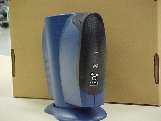
Click to zoom
Application Details
- Equipment Class
- PCB - PCS Licensed Transmitter
- Date of Grant
- Nov 25, 2001
- Application Purpose
- Original Equipment
- Date of Application
- Nov 25, 2001
- Equipment Note
- Wide CDMA WLL Subscriber Terminal
- Frequency Range
- 1852.50000000 - 1907.50000000
- Company
- SOMA Networks, Inc.
- Country
- United States
Documents & Files
Document Text
Text extracted from the exhibit documents filed with the FCC. Open a document above to read the original.
Users Manual
SOMAport 140 Setup Guide Document ID:OPN-USER.0003 Date:August 30, 2001 Author Information Revision History AuthorE-mailPhone # Irene [email protected] StatusVersionDateChanges Made Draft0.01March 8, 2001Document created Draft0.02March 23, 2001 Comments from subject matter expert review incorporated Initial Draft0.03April 10, 2001Comments from editor incorporated Initial Draft0.04May 15, 2001Illustrations incorporated. Further edits incorporated. Index created. Initial Draft0.05June 26, 2001Incorporated comments from Bernard Kraemer for CFT release. Initial Draft0.06Aug. 15, 2001CFT version Initial Draft0.07Aug. 30, 2001Footers changed for CFT version Proprietary and Confidential 3 Copyright 2001 SOMA Networks, Inc. All Rights Reserved. SOMA Networks, Inc. 185 Berry Street Suite 2000 San Francisco, CA 94107 U.S.A. Phone +1 415 882 6500 Fax +1 415 882 6501 SOMA Networks, Inc. 312 Adelaide Street West Suite 700 Toronto, ON M5V 1R2 Canada Phone +1 416 977 1414 Fax +1 416 977 1505 SOMA, SOMA Networks, and the star-and-circle logo are trademarks of SOMA Networks, Inc. All of SOMA Networks’ product names are trademarks of SOMA Networks, Inc. All other company and product names may be trademarks or registered trademarks of their respective owners. SOMA Networks, Inc. assumes no responsibility for the accuracy or completeness of the information presented or for any use of the information contained in this document. SOMA Networks, Inc. reserves the right to, without notice, make change to its products as progress in engineering or manufacturing methods or circumstances may warrant. 4Proprietary and Confidential Proprietary and Confidential 5 Important Safety Instructions Installation Read Instructions — All the safety and operating instructions should be read before the product is operated. Retain Instructions — The safety and operating instructions should be retained for future reference. Heed warnings — All warnings on the product and in the operating instructions should be adhered to. Follow instructions — All operating and use instructions should be followed. Ventilation — Slots and openings in the product housing are provided for ventilation and to ensure reliable operation of the product and to protect it from overheating. These openings must not be blocked or covered. The openings should never be blocked by placing the product on a bed, sofa, rug, or other similar surface. This product should not be placed in a built-in installation such as a bookcase or rack unless proper ventilation is provided or the manufacturer’s instructions have been adhered to. Power sources — This product should be operated only from the type of power source indicated on the marking label. If you are not sure of the type of power supplied to your home, consult your product dealer or local power company. Grounding or polarization — This product is equipped with a plug that will fit into the power outlet only one way. If you are unable to insert the plug fully into the outlet, try reversing the plug. If the plug still fails to fit, contact your electrician to replace your outlet. To prevent electric shock, do not use this plug with an extension cord or outlet unless you can fully insert the blades without blade exposure. Do not defeat the safety purpose of this plug. Power-cord protection — Power-supply cords should be routed so that they are not likely to be walked on or pinched by items placed upon or against them, paying particular attention to cords at the plug and the point where they exit from the product. Accessories — To avoid personal injury or damage to the product, do not place it on an unstable cart, stand, tripod, bracket, or table. Attachments — Do not use attachments unless recommended by the product manufacturer as they may cause hazards. Water and moisture — Do not use this product near water or moisture. 6Proprietary and Confidential Maintenance and servicing Cleaning — Unplug this product from the wall outlet before cleaning. Do not use liquid cleaners or aerosol cleanser. Use a damp cloth for cleaning. Servicing — Do not attempt to service this product yourself as opening or removing covers may expose you to dangerous voltage or other hazards. There are no user serviceable parts inside. Refer all servicing to qualified service personnel. Replacement parts — When replacement parts are required, have the technician verify that the replacements being used have the same safety characteristics as the original parts. Use of replacement parts specified by the product manufacturer can prevent fire, electric shock, or other hazards. Conditions requiring service — Unplug this product from the wall outlet and refer servicing to qualified service personnel under the following conditions: When the power supply or cord is damaged. If liquid has been spilled on, or objects have fallen into, the product or it has been exposed to water. If the product does not operate normally by following the operating instructions adjust only those controls that are covered by the operating instructions. Improper adjustment of other controls may result in damage and will often require extensive work by a qualified technician to restore the product to its normal operation. If the product has been dropped or the product housing has been damaged. When the product exhibits a distinct change in performance. Alerts used in this guide WARNING: Where you see this symbol and the WARNING heading, strictly follow the instructions to avoid personal injury or damage to the product. WARNING: Where you see this symbol and the WARNING heading, strictly follow the instructions to avoid electric shock. Proprietary and Confidential 7 Regulatory Notices This equipment has been tested and found to comply with the limits for a Class B digital device, pursuant to Part 15 of the FCC Rules. These limits are designed to provide reasonable protection against harmful interference in a residential installation. This e…
Text truncated - open the document above for the full version.
Cover Letter(s)
American Telecommunications Certification Body Inc. 6731 Whittier Ave, McLean, VA 22101 • November 15, 2001 RE: SOMA Networks FCC ID: POZ-CPE-0140A-000 One final comment on the manual: 1.) The following note will appear on the Grant: “The antenna installation and operating configurations of this transmitter, including antenna gain and cable loss must satisfy MPE categorical Exclusion Requirements of §2.1091. The antenna(s) used for this transmitter must be installed to provide a separation distance of at least 20 cm from all persons and must not be co-located or operating in conjunction with any other antenna or transmitter. Users and installers must be provided with antenna installation instructions and transmitter operating conditions for satisfying RF exposure compliance .” Please add co-location language to the manual RF warning statements. William H. Graff Examining Engineer President and Director of Engineering mailto:[email protected] The items indicated above must be submitted before processing can continue on the above referenced application. Failure to provide the requested information may result in application termination. Correspondence should be considered part of the permanent submission and may be viewed from the Internet after a Grant of Equipment Authorization is issued. Please do not respond to this correspondence using the email reply button. In order for your response to be processed expeditiously, you must submit your documents through the AmericanTCB.com website. Also, please note that partial responses increase processing time and should not be submitted. Any questions about the content of this correspondence should be directed to the sender.
Cover Letter(s)
American Telecommunications Certification Body Inc. 6731 Whittier Ave, McLean, VA 22101 October 23, 2001 RE: SOMA Networks FCC ID: POZ-CPE-0140A-000 Please address the following concerns on this Application. 1.) All Licensed equipment Applications must have a Parts List. Please upload to the AmericanTCB website. 2.) Please provide a conducted RF power output measurement for proper evaluation of RF Exposure criteria. 3.) The Form 731 requests a lower frequency range of 1850.5 MHz and an upper range of 1909.5 MHz. Using your reported emission designator, I would expect this 5MHz wide emission to hang over the band edge by 2 MHz. Please resolve. 4.) Compliance with the band edge provisions of 24.238(a), (b), and (c) do not seem to be presented at as close as possible to 1850 or 1910 MHz. Please note that using the 1% rule for setting your RBW, you can be greater but never less. This means for an emission 5MHz wide the RBW cannot be less than 50KHz. 5.) Block Diagrams are not required for any Licensed equipment approval. However, if you desire to submit one it should meet the requirements of 2.1033(b) (5). 6.) Please show how you arrived at the 5M00FXW emission designator. 7.) Is this device adjustable in power? It is unusual for CDMA equipment to operate with fixed power. If so a minimum power should be specified on Form 731 per 2.1033(c)(6). 8.) Please provide tune up information per 2.1033(c)(9). What I am looking for is tune up information for the radio section. 9.) Please provide description of digital modulation techniques per 2.1033(c)(13). A statement that W-CDMA is employed is insufficient due to the number of wide CDMA schemes available. 10.) Please be aware that the Internal Photographs may not be of sufficient clarity to meet the FCC’s expectations. I will accept them, but urge you to obtain larger and clearer photos. William H. Graff Examining Engineer President and Director of Engineering mailto:[email protected] The items indicated above must be submitted before processing can continue on the above referenced application. Failure to provide the requested information may result in application termination. Correspondence should be considered part of the permanent submission and may be viewed from the Internet after a Grant of Equipment Authorization is issued. Please do not respond to this correspondence using the email reply button. In order for your response to be processed expeditiously, you must submit your documents through the AmericanTCB.com website. Also, please note that partial responses increase processing time and should not be submitted. Any questions about the content of this correspondence should be directed to the sender.
Cover Letter(s)
RE: SOMA Networks FCC ID: POZ-CPE-0140A-000 1.) All Licensed equipment Applications must have a Parts List. Please upload to the AmericanTCB website. Response: Uploaded as requested. FYI: In past submission I have not submitted part list for license devices, so I e-mail Frank and ask if a part-list still needed to be submitted for a license devices and this is what he mention: “A parts list may be requested by the reviewing engineer on a case-by-case basis.” 2.) Please provide a conducted RF power output measurement for proper evaluation of RF Exposure criteria. Response: Uploaded to the RF exposure info and label “Power Output” 3.) The Form 731 requests a lower frequency range of 1850.5 MHz and an upper range of 1909.5 MHz. Using your reported emission designator, I would expect this 5MHz wide emission to hang over the band edge by 2 MHz. Please resolve. Response: Please change the frequency range to 1852.5 to 1907.5 MHz. 4.) Compliance with the band edge provisions of 24.238(a), (b), and (c) do not seem to be presented at as close as possible to 1850 or 1910 MHz. Please note that using the 1% rule for setting your RBW, you can be greater but never less. This means for an emission 5MHz wide the RBW cannot be less than 50KHz. Response: As you are aware Section 24.238 (c) states “....as the design permits.” The software developed by SOMA only permits from 1852.5 to 1907.5 MHz. This is the way they design it. Bandedge measurements were made at RBW: 30 kHz. The level measured at the bandedge was corrected to 41 kHz by using the following formula 10*Log(1% RBW/RBW used for the measurement) dB. (10*log (41/30) = 1.4 dB correction). This is what Frank suggested to do, when using a lower RBW then the 1% rule. Uploaded a revised data, which included this formula and correction. 5.) Block Diagrams are not required for any Licensed equipment approval. However, if you desire to submit one it should meet the requirements of 2.1033(b) (5). Response: Thanks for letting me know about this. Please remove Block Diagram. 6.) Please show how you arrived at the 5M00FXW emission designator. Response: The 5 MHz is the industry standard Bandwidth for a W-CDMA. But, the measured 99% gave me 4.183 MHz. Please change the emission designator to 4M18FXW. Please let me know if this satisfies your requirement, so we can re-upload a revised report with the new emission designator. 7.) Is this device adjustable in power? It is unusual for CDMA equipment to operate with fixed power. If so a minimum power should be specified on Form 731 per 2.1033(c)(6). Response: The minimum output power is – 45 dBm. 8.) Please provide tune up information per 2.1033(c)(9). What I am looking for is tune up information for the radio section. Response: The tune-up procedure has been uploaded to the Parts list exhibit. 9.) Please provide description of digital modulation techniques per 2.1033(c)(13). A statement that W-CDMA is employed is insufficient due to the number of wide CDMA schemes available. Response: A basic explanation of the W-CDMA modulation has been uploaded to the Operational Description and label “Digital Modulation Operation”. Here is what I will mention: W-CDMA is a "direct-sequence spread spectrum" technique. It is similar to IS-95, but with a wider (5 MHz) carrier. SOMA's air interface is a variant of W-CDMA (aka 3GPP), and uses the same chip rate of 3.84 Mcps. In addition to the standard QPSK modulation scheme contained in W-CDMA, SOMA's radio system utilizes higher-order modulation: 16- and 64-QAM. 10.) Please be aware that the Internal Photographs may not be of sufficient clarity to meet the FCC’s expectations. I will accept them, but urge you to obtain larger and clearer photos. Response: SOMA has been notified. Please proceed with the photos you have for now. SOMA is in the process of providing us more photos.
External Photos
FRONT SIDE OF UNIT SIDE VIEW OF UNIT BACK SIDE OF UNIT
ID Label/Location Info
MARK VENDOR NAME, LABEL DESIGNATION, AND SOMA NETWORKS PART NUMBER ON EACH SHEET OF LABELS. 2. BACKGROUND TO BE BLACK. LETTERING AND GRAPHICS TO BE SILVER. REFER TO APPROPRIATE AGENCY LISTING MARK INFORMATION TO REPLACE REFERENCE SYMBOLS WITH APPROPRIATE REGISTERED MARKS. FONT: ARIAL 14 POINT FONT: ARIAL 5 POINT FONT: ARIAL 9 POINT 7. LABEL CONSTRUCTION TO CONSIST OF A 0.010" THICK POLYCARBONATE LABEL STOCK WITH A 0.005" THICK 3M 468 PRESSURE SENSITIVE ADHESIVE . LABEL MUST BE A COMPONENT MARKING AND LABELING SYSTEM APPROVED BY UL AND CSA FOR THE FOLLOWING CONDITIONS: -INDOOR - TEMPERATURE RANGE: -40C TO +55C WHEN AFFIXED TO PLASTIC (HAPCO ULTRALOY 912 CAST POLYURETHANE) 8. APPROVED SOURCES OF SUPPLY: BAY AREA LABELS SERIAL NUMBER LABEL TO BE AFFIXED AT INDICATED LOCATION. 10. REFERENCE DOCUMENT "SOMAPORT140 REGULATORY LABEL REV 2.AI" FOR LABEL LAYOUT. 11. REFERENCE DOCUMENT "SOMAPORT140 REGULATORY LABEL REV 2.DXF" FOR LABEL OUTLINE. "ITE 91LF / E217858" AT NOTED LOCATION. FCC PART 15 COMPLIANCEThis device complies with Part 15 of the FCC Rules. Operation is subject to the following two conditions:1) This device may not cause harmful interference.2) This device must accept any interference recieved, including interference that causes undesired operation. SOMAport 140Model: CPE-0140A-000 CAUTION: FOR INDOOR USE ONLY!USE ONLY WITH APPROVED POWER SUPPLY.INPUT RATING: 15 V DC 1.8 A MAXIMUM 6 5 4 3 3 4 5 6 1 Made in U.S.A. P/N: 001091-000 S/N: 9 6 9 US LISTED ITE 91LFE217858 C 6 12 12 FCC ID: POZ-CPE-0140A-000 NOT RELEASED NOT RELEASED NOT RELEASED FCC ID added in this location. 4.48 3.75 D C B A A B C D NETWORKS CAD GENERATED DRAWING, DO NOT MANUALLY UPDATE SCALE SIZE CAD FILE: DWG. NO. B SHEET1OF1 REV. DATE APPROVALS DRAWN CHECKED RESP ENG MFG ENG QUAL ENG UNLESS OTHERWISE SPECIFIED DIMENSIONS ARE IN INCHES TOLERANCES ARE: FRACTIONS DECIMALS ANGLES + .XX+ .XX + 1 .XXX+.XXX MATERIAL FINISH -- -- DO NOT SCALE DRAWING APPLICATION USED ONNEXT ASSY ITEM NO. PART OR IDENTIFYING NO. NOMENCLATURE OR DESCRIPTION MATERIAL SPECIFICATION QTY REQD PARTS LIST 123 456 7 8 87 6 5 4 32 1 THE INFORMATION CONTAINED IN THIS DRAWING IS THE SOLE PROPERTY OF SOMA NETWORKS. ANY REPRODUCTION IN PART OR WHOLE WITHOUT THE WRITTEN PERMISSION OF SOMA NETWORKS IS PROHIBITED. REVISIONS REV.DESCRIPTION DATEAPPROVED 001093-000 2 LABEL, REGULATORY, U.S.A., CFT-1 1 INITIAL RELEASE FOR QUOTATION / PROTOTYPE PRODUCTION4/25/01 A. HUDSON A. HUDSON 6/4/01 6/4/01 2 ADDED ITE NUMBER AND CORRECT UL LOGO6/4/01
ID Label/Location Info
FCC LABEL LOCATION
Internal Photos
PHONE INTERFACE CARD RF BOARD INTERIOR COMPLETE ASSEMBLY OF UNIT FOR MORE INFORMATION PLEASE REFER TO BLOCK DIAGRAM ON PAGE 85 OF THE THEORY OF OPERATION RF BOARD WITH INTERNAL ANTENNA REFER TO THEORY OF OPERATION IN PAGES 88 & 89 FOR MORE INFORMATION SOLDER SIDE OF PHONE INTERFACE CARD REFER TO THEORY OF OPERATION IN PAGE 93 FOR MORE INFORMATION COMPONENT SIDE OF PHONE INTERFACE CARD BASEBAND CARD COMPONENT SIDE VIEW REFER TO THEORY OF OPERATION IN PAGE 90 FOR MORE INFORMATION SOLDER SIDE OF BASEBAND CARD REFER TO THEORY OF OPERATION IN PAGE 90 FOR MORE INFORMATION
Test Report
File: R43601 Page 1 of 16 Electromagnetic Emissions Test Report In Accordance With FCC Part 24 Subpart E on the SOMAport Wireless Terminal Model: CPE-0140A-000 GRANTEE: SOMA Networks, Inc. 400 Industrial Street, Suite 100 Reichardson, Tx 75081 TEST SITE: Elliott Laboratories, Inc. 684 W. Maude Ave Sunnyvale, CA 94086 REPORT DATE: October 4, 2001 FINAL TEST DATE: April 25 and 26, 2001 AUTHORIZED SIGNATORY: ______________________________ David Bare Chief Technical Officer This report shall not be reproduced, except in its entirety, without the written approval of Elliott Laboratories, Inc. Elliott Laboratories, Inc. -- EMC Department Test Report Report Date: October 4, 2001 File: R43601 Page 2 of 16 pages TABLE OF CONTENTS COVER PAGE..................................................................................................................................................................................1 TABLE OF CONTENTS...............................................................................................................................................................2 FCC CERTIFICATION INFORMATION..................................................................................................................................3 SCOPE.............................................................................................................................................................................................5 OBJECTIVE...................................................................................................................................................................................5 EMISSION TEST RESULTS.......................................................................................................................................................6 SECTION 2.1046: RF POWER OUTPUT................................................................................................................................6 SECTION 2.1047: MODULATION CHARACTERISTICS..................................................................................................6 Section 2.1047 (d) Other types of equipment................................................................................................................6 SECTION 2.1051: SPURIOUS EMISSION AT ANTENNA TERMINAL..........................................................................6 SECTION 2.1053: FIELD STRENGTH OF SPURIOUS RADIATION................................................................................7 SECTION 2.1055: FREQUENCY STABILITY........................................................................................................................7 EQUIPMENT UNDER TEST (EUT) DETAILS..........................................................................................................................8 GENERAL...................................................................................................................................................................................8 ENCLOSURE..............................................................................................................................................................................8 MODIFICATIONS....................................................................................................................................................................8 SUPPORT EQUIPMENT..........................................................................................................................................................9 EUT INTERFACE PORTS........................................................................................................................................................9 EUT OPERATION.....................................................................................................................................................................9 TEST SITE....................................................................................................................................................................................10 GENERAL INFORMATION..................................................................................................................................................10 CONDUCTED EMISSIONS CONSIDERATIONS..............................................................................................................10 RADIATED EMISSIONS CONSIDERATIONS..................................................................................................................10 MEASUREMENT INSTRUMENTATION................................................................................................................................11 RECEIVER SYSTEM...............................................................................................................................................................11 INSTRUMENT CONTROL COMPUTER............................................................................................................................11 POWER METER......................................................................................................................................................................11 FILTERS/ATTENUATORS...................................................................................................................................................11 ANTENNAS............................................................................................................................................................................12 ANTENNA MAST AND EQUIPMENT TURNTABLE....................................................................................................12 INSTRUMENT CALIBRATION...........................................................................................................................................12 TEST PROCEDURES....................................................................…
Text truncated - open the document above for the full version.
Test Report
EMC Test Data Emissions Spec: Immunity Spec: Contact: Client: Model: Soma Networks Soma Networks CPE-0140A-000 Steve Fielding J43169 T43171 David Bare Job Number: T-Log Number: Proj Eng: Model CPE-0140A-000 Part 24 Subpart E - N/A -Environment: Class: EMC Test Data For The T-Log: T43171, Rev 1.0CoverPage 1 of 16 EMC Test Data The EUT is a wireless terminal which is designed to provide wireless network access in homes. Normally, the EUT would be placed on a table top during operation. The EUT was, therefore, treated as table-top equipment during testing to simulate the end user environment. The electrical rating of the EUT is 120/240 V, 50/60 Hz, 2 Amps. The EUT enclosure is primarily constructed of fabricated sheet steel. It measures approximately 12 cm wide by 22 cm deep by 28 cm high. EUT Enclosure N/A FCC ID POZ-CPE-0140A-000 - CPE-0140A-000Wireless Terminal Emissions Spec: DescriptionModel Soma Networks EUT INFORMATION Serial Number Equipment Under Test Client: Model: J43169 T43171 Soma Networks CPE-0140A-000 David Bare Job Number: T-Log Number: Proj Eng: Contact: Steve Fielding Immunity Spec: Manufacturer General Description N/A -Environment: Class:Part 24 Subpart E Modification History Mod. #TestDateModification 1None-- T-Log: T43171, Rev 1.0EUT DescripPage 2 of 16 EMC Test Data RS-232Shielded1.5 4xTelephoneUnterminatedRJ-11Unshielded2 SerialPC 2 EthernetPCRJ-45Unshielded1.5 USBUnterminatedUSBShielded Remote Support Equipment EUT Interface Ports FCC ID EUT was set to transmit continuously at the low and high bandedges. Emissions Spec: Immunity Spec: Contact: Manufacturer Steve Fielding Part 24 Subpart E - N/A EUT Operation During Emissions Client: Model: Soma Networks CPE-0140A-000 J43169 T43171 David Bare Job Number: T-Log Number: Proj Eng: Serial Number -Environment: Class: FCC ID Test Configuration #1 ModelDescriptionSerial Number Local Support Equipment None ManufacturerModelDescription EUT Port Cable(s) Shielded or UnshieldedLength(m)DescriptionConnected To DoC MitsubishiDiamond Plus 91Monitor011A34108DoC HPPavilion 7840PCKR10504395 DoC HPM-S34MouseLZS04915643DoC HP5181KeyboardBD05106245 DS16XU2225HP2225CPrinterZ714S40166 T-Log: T43171, Rev 1.0Test Configuration #1Page 3 of 16 EMC Test Data Client: Contact: Spec: Test Specifics General Test Configuration Ambient Conditions: Summary of Results Result Pass Soma NetworksJob Number: J43169 Steve Fielding Part 24 Subpart EClass:N/A Model: CPE-0140A-000T-Log Number: T43171 Proj Eng: David Bare Section 2.1046: RF Power Objective: The objective of this test session is to perform final qualification testing of the EUT with respect to the specification listed above. Date of Test: 4/25/01Config. Used: 1 Test Engineer: jmartinezConfig Change: None Test Location: SVOATS #3EUT Voltage: 120V/60Hz The EUT was located on the turntable for radiated field strength measurements and the local support equipment was located underneath the table. For radiated emissions testing the measurement antenna was located 3 meters from the EUT. Temperature: 23°C Rel. Humidity: 31% Run #Test PerformedLimitMeasurement 1Radiated Output Power24.232(b)32.1 dBm (EIRP) Modifications Made During Testing: No modifications were made to the EUT during testing Deviations From The Standard No deviations were made from the requirements of the standard. T-Log: T43171, Rev 1.0RF PowerPage 4 of 16 EMC Test Data Client: Contact: Spec: Soma NetworksJob Number: J43169 Steve Fielding Part 24 Subpart EClass:N/A Model: CPE-0140A-000T-Log Number: T43171 Proj Eng: David Bare Run #1: Radiated Output Power (EIRP) With Integral Antenna. Channel Antenna Pol. (H/V) Res BW LowH1 MHz HighH1 MHz LowV1 MHz HighV1 MHz Note 1: Note 2: Run #2: Output Power (Substitution Method) Comments FrequencyLevelPolPinGainEIRPLimit MHz dBμV/m v/h(dBm)(dBi)(dBm)(dBm) 1848.10127.4v25.17.032.133.0 1848.10124.7h19.97.026.933.0 1906.60125.9v23.27.430.633.0 1906.60120.6h21.27.428.633.0 Substitution Note 1 Frequency (MHz)Field Strength at 3m 1848.1124.67 Add note here 1906.6125.89 1906.6120.63 1848.1127.42 T-Log: T43171, Rev 1.0RF PowerPage 5 of 16 EMC Test Data Client: Contact: Spec: Test Specifics General Test Configuration Ambient Conditions: Summary of Results Result Pass Modifications Made During Testing: No modifications were made to the EUT during testing Deviations From The Standard No deviations were made from the requirements of the standard. 3Occupied Bandwidth24.238(b)BW= 4.183 MHz Plot #Test PerformedLimitComment When performing conducted measurements from the EUT’s antenna port, the antenna port of the EUT was connected to the spectrum analyzer or power meter via a suitable attenuator to prevent overloading the measurement system. All measurements are corrected to allow for the external attenuators used. Temperature: 23°C Rel. Humidity: 31% Section 2.1049: Occupied Bandwidth Objective: The objective of this test session is to perform final qualification testing of the EUT with respect to the specification listed above. Test Location: SVOATS #3EUT Voltage: 120V/60Hz Test Engineer: jmartinezConfig Change: None Date of Test: 4/26/01Config. Used: 1 Steve Fielding Part 24 Subpart EClass:N/A Soma NetworksJob Number: J43169 Model: CPE-0140A-000T-Log Number: T43171 Proj Eng: David Bare T-Log: T43171, Rev 1.0Occupied BanwidthPage 6 of 16 EMC Test Data Client: Contact: Spec: Steve Fielding Part 24 Subpart EClass:N/A Soma NetworksJob Number: J43169 Model: CPE-0140A-000T-Log Number: T43171 Proj Eng: David Bare T-Log: T43171, Rev 1.0Occupied BanwidthPage 7 of 16 EMC Test Data Client: Contact: Spec: Test Specifics General Test Configuration Ambient Conditions: Summary of Results Result Pass Pass Pass Pass7Out-Of-Band24.238(a)- The EUT and all local support equipment were located on the table for testing. The Eut was connected directly to Test Receiver. A 20-dB attenuator was used between the EUT and Test Receiver. Deviations From The Standard No deviations were made from the requirements of the standard. Modificati…
Text truncated - open the document above for the full version.
Contact Information
Applicant
Robin Grindley(Chief Scientist-Hardware Systems)
Technical Contact
Elliott Laboratories Inc.Juan Martinez
[email protected]408 245 7800
684 W. Maude Ave · Sunnyvale, California · United States
Test Firm
Elliott Laboratories LLCDavid Bare
Technical Specifications
| # | Rule Parts | Frequency Range | Power Output | Emission | Tolerance |
|---|---|---|---|---|---|
| 1 | 24E | 1.85 GHz - 1.91 GHz | 1.585 W | 4M18FXW | 3.0000000000 Hz |
Other Applications from SOMA Networks, Inc.
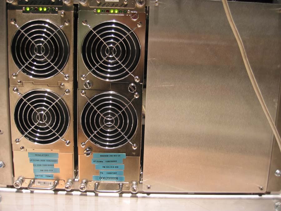
POZNPM700007168A
Sep 06, 2006FBS Wireless Base Station (NPM-2500)
Equipment Class
TNB - Licensed Non-Broadcast Station Transmitter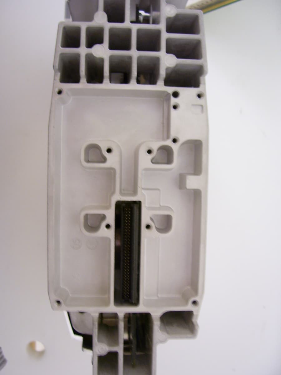
POZCPE700006553D
Aug 30, 2006CPE-300-2C0 (SOMAport Subscriber Terminal)
Equipment Class
TNB - Licensed Non-Broadcast Station Transmitter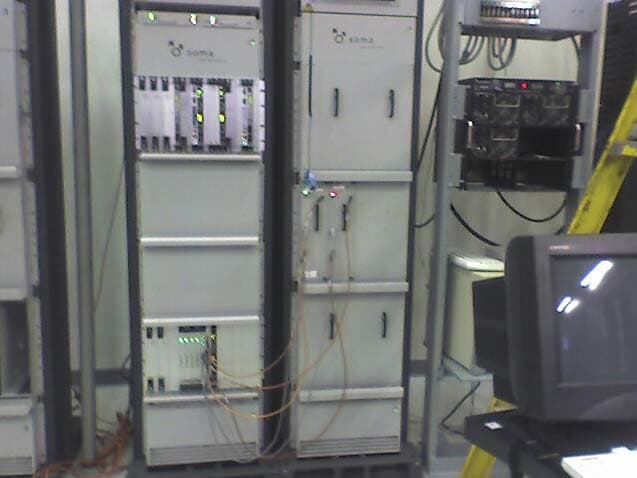
POZNPMWCS005777A
Apr 26, 2006NPM Wireless Base Station
Equipment Class
TNB - Licensed Non-Broadcast Station Transmitter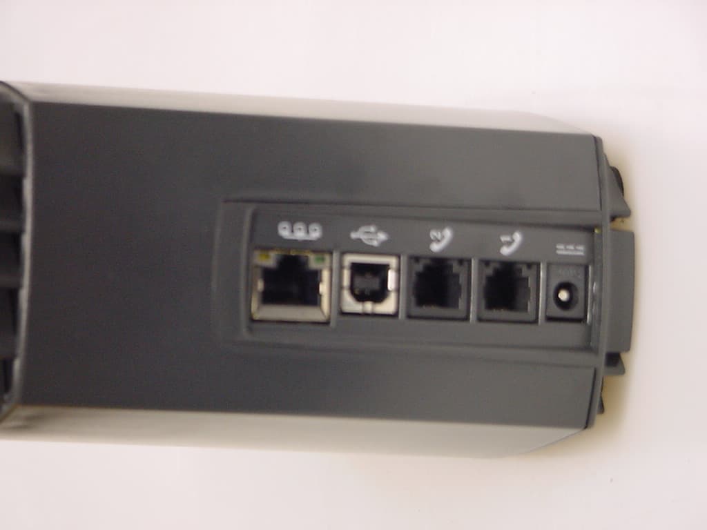
POZCPEWCS005239B
Apr 26, 2006SOMAport Subscriber wireless terminal
Equipment Class
TNB - Licensed Non-Broadcast Station Transmitter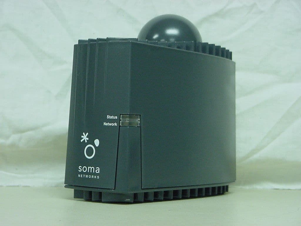
POZCPEPCS004886C
Sep 28, 2004SOMAport Subscriber Terminal
Equipment Class
PCB - PCS Licensed Transmitter