POZCPEPCS004886CSOMAport Subscriber Terminal
SOMA Networks, Inc.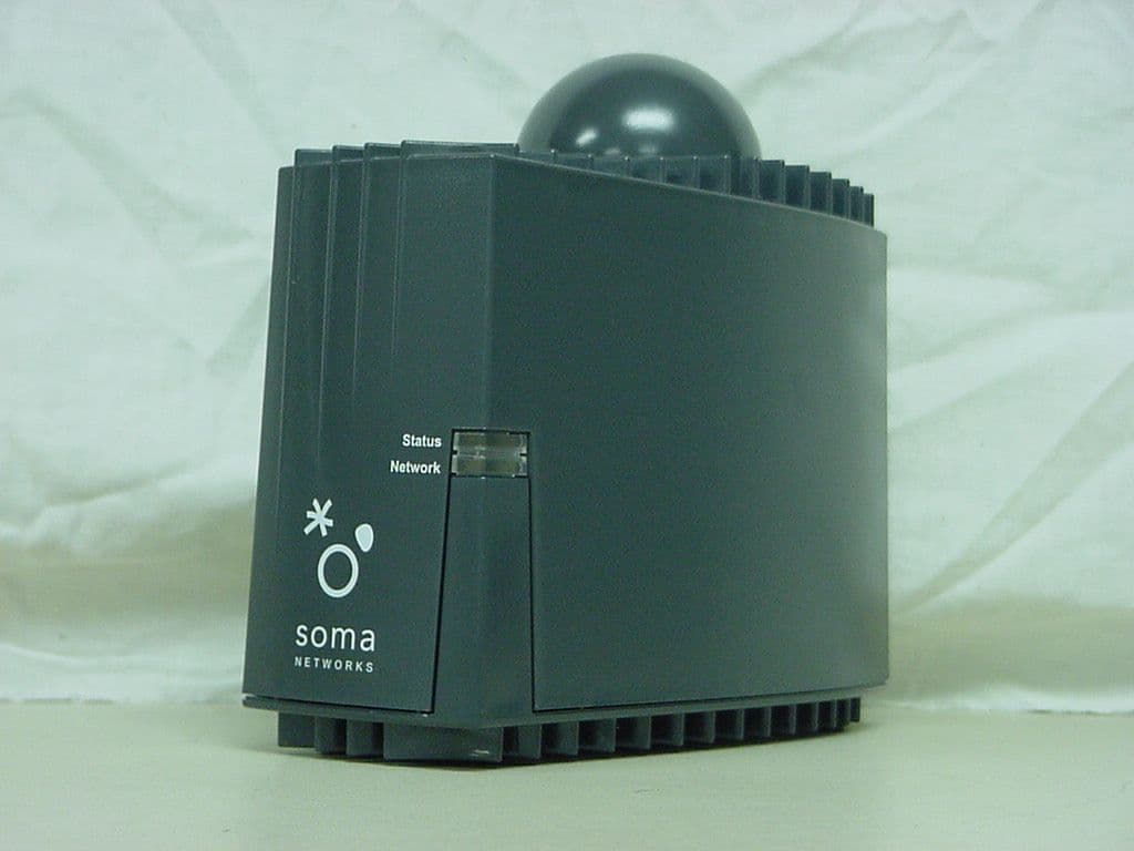
Click to zoom
Application Details
- Equipment Class
- PCB - PCS Licensed Transmitter
- Date of Grant
- Sep 28, 2004
- Application Purpose
- Original Equipment
- Date of Application
- Sep 28, 2004
- Equipment Note
- SOMAport Subscriber Terminal
- Frequency Range
- 1852.50000000 - 1907.50000000
- Company
- SOMA Networks, Inc.
- Country
- United States
Documents & Files
Document Text
Text extracted from the exhibit documents filed with the FCC. Open a document above to read the original.
Users Manual
1 Contents July 22, 2004 Part 004840A Rev 01 Introduction............................................................................ 9 Overview. . . . . . . . . . . . . . . . . . . . . . . . . . . . . . . . . . . . . . . . . . . . . .10 The Front Panel . . . . . . . . . . . . . . . . . . . . . . . . . . . . . . . . . . . . . . . .11 The Back Panel . . . . . . . . . . . . . . . . . . . . . . . . . . . . . . . . . . . . . . . .13 The Internal Antenna . . . . . . . . . . . . . . . . . . . . . . . . . . . . . . . . . . . .14 Installing the SOMAport...................................................... 15 Unpack the SOMAport . . . . . . . . . . . . . . . . . . . . . . . . . . . . . . . . . . .16 Choose the Best Location . . . . . . . . . . . . . . . . . . . . . . . . . . . . . . . .17 Power on the SOMAport. . . . . . . . . . . . . . . . . . . . . . . . . . . . . . . . . .18 Connect Computer Using Ethernet. . . . . . . . . . . . . . . . . . . . . . . . . .19 Connect Computer Using USB. . . . . . . . . . . . . . . . . . . . . . . . . . . . .20 Connect Multiple Computers to the SOMAport . . . . . . . . . . . . . . . .22 Connect Telephones to the SOMAport. . . . . . . . . . . . . . . . . . . . . . .23 Activate Service . . . . . . . . . . . . . . . . . . . . . . . . . . . . . . . . . . . . . . . .27 Troubleshooting .................................................................. 29 Finding Causes of Computer Problems . . . . . . . . . . . . . . . . . . . . . .30 Finding Causes of Telephone Problems . . . . . . . . . . . . . . . . . . . . .31 The Signal is Weak. . . . . . . . . . . . . . . . . . . . . . . . . . . . . . . . . . . . . .32 There is a Fault Condition . . . . . . . . . . . . . . . . . . . . . . . . . . . . . . . .33 The SOMAport is Not Receiving Power . . . . . . . . . . . . . . . . . . . . . .34 There is a Problem with the Ethernet or USB Cabling . . . . . . . . . . .35 There is a Problem with the USB Port Settings . . . . . . . . . . . . . . . .37 The Computer Uses an Old Dial-Up Connection . . . . . . . . . . . . . . .38 Internet Explorer LAN Settings are Incorrect . . . . . . . . . . . . . . . . . .40 Ethernet Network Settings are Incorrect. . . . . . . . . . . . . . . . . . . . . .41 IP address Needs to be Renewed . . . . . . . . . . . . . . . . . . . . . . . . . .50 Specifications ..................................................................... 53 Index .................................................................................... 55 sp3.book Page 1 Thursday, July 22, 2004 3:21 PM 2 sp3.book Page 2 Thursday, July 22, 2004 3:21 PM 3 SOMA NETWORKS INC. ENDUSER PRODUCT LICENSE AGREEMENT THE SOMAPORT™ SUBSCRIBER TERMINAL AND PROVIDED SOFTWARE CONTAIN CERTAIN COMPUTER PROGRAMS AND OTHER PROPRIETARY MATERIAL OF SOMA NETWORKS INC. OR LICENSED TO SOMA NETWORKS, INC., THE USE OF WHICH IS SUBJECT TO THIS AGREEMENT. BY: (A) SIGNING AN AGREEMENT FOR SERVICE WITH YOUR SERVICE PROVIDER; (B) OPENING THE SEALED ENVELOPE CONTAINING THE SOMAPORT; OR (C) USING THE SOMAPORT, YOU ASSENT TO AND ACCEPT THIS ENDUSER PRODUCT LICENSE AGREEMENT. IF YOU DO NOT AGREE WITH ALL THE TERMS OF THIS AGREEMENT YOU MUST RETURN THIS PRODUCT (WITH THE ENVELOPE STILL SEALED), ALL MANUALS AND DOCUMENTATION, ANY SOFTWARE PACKAGES PROVIDED WITH THE SOMAPORT AND PROOF OF PAYMENT TO THE PLACE YOU OBTAINED THEM FOR A FULL REFUND WITHIN THIRTY (30) DAYS OF FIRST ACQUIRING THE SOMAPORT, OTHERWISE YOU ARE DEEMED TO HAVE ACCEPTED AND AGREED TO THESE TERMS AND CONDITIONS. UNAUTHORIZED REPRODUCTION, DISTRIBUTION, DECOMPILATION OR OTHER REVERSE ENGINEERING OF THIS PRODUCT INCLUDING ITS HARDWARE AND/OR SOFTWARE, OR ANY PORTION OF IT, IS PROHIBITED AND MAY RESULT IN SEVERE CIVIL AND CRIMINAL PENALTIES, AND WILL BE PROSECUTED TO THE MAXIMUM EXTENT POSSIBLE UNDER THE LAW. 1. GRANT OF LICENSE: Subject to the terms of this Enduser Product License Agreement (the “Agreement”), SOMA Networks, Inc. (“SOMA”) grants you (the “Licensee”) a non-sub-licensable, non-exclusive right (“License”) to use the Product. “Product” means, collectively, the Software and the provided hardware, and specifically the SOMAport™ subscriber terminal and its accessories, if any, together with documentation provided to you by SOMA or your service provider. “Software” means, collectively, the version of the SOMA software program in object code format and all updates to that program distributed to you by SOMA, directly or indirectly, by any means and includes any firmware provided to you with the Product. You have no right, unless otherwise explicitly permitted, to receive any source code or design documentation relating to the Product. SOMA retains ownership of all Software copies. The Software and this License is only provided to you to be used in conjunction with the SOMAport provided to you by SOMA or your service provider when you subscribed to services that utilize the SOMA wireless air interface technology and is not licensed to you to be used for any other purpose. 2. RESTRICTIONS: Except as reasonably required to use the Product strictly in accordance with the License and this Agreement, you may not copy any Software. Licensee shall not (and shall not allow any third party to): (I) decompile, disassemble, or otherwise reverse engineer or attempt to reconstruct or discover any source code or underlying ideas or algorithms or file formats or programming or interoperability interfaces of the Product by any means whatsoever; (II) remove any Product identification, copyright or other notices; (III) modify, incorporate into or with other software or create a derivative work of any part of the Software or Product; or (IV) modify or otherwise alter the operation of the Product. Various components, functions, routines and/or portions of the Product may be protected by Intellectual Property Rights (“IPR”) including, but not limited to, designs, copyrights, trade secrets and one or more patents or pending patent applications. Licensee is licensed under such…
Text truncated - open the document above for the full version.
Cover Letter(s)
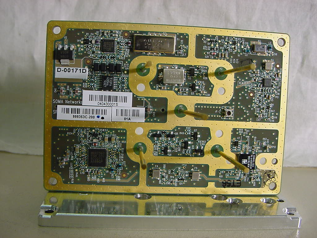
Chris Harvey From: Chris Harvey [[email protected]] Sent: Monday, September 06, 2004 8:41 AM To: 'Chris Harvey'; Alvin Ilarina ([email protected]); Kerwin Corpuz ([email protected]) Cc: 'Marianne Bosley' Subject: RE: Additional Information needed for SOMA FCC ID: POZCPEPCS004886C MT#15478 Page 1 of 2 9/6/2004 Please add this one additional request to the list below: 6. The internal photographs submitted show the general construction of this device. Please provide additional internal photographs showing both sides of all PC Boards in this device. Beset regards, Chris -----Original Message----- From: Chris Harvey [mailto:[email protected]] Sent: Monday, September 06, 2004 8:37 AM To: Alvin Ilarina ([email protected]); Kerwin Corpuz ([email protected]) Cc: 'Marianne Bosley' Subject: Additional Information needed for SOMA FCC ID: POZCPEPCS004886C MT#15478 Kerwin/Alvin, I have reviewed the application for SOMA referenced above and have the following items that need to be addressed in order to continue this TCB application review: 1. The RF Power measurements in this report are stated as RF Conducted Power. Devices that have integral antennas in the FCC Pt. 24 Subpart E allocation are required to have EIRP measurements. Please submit measured EIRP using the Substitution Method of EIA/TIA 603. 2. Please provide the method of determining the 5M00F9W Emission Designator stated in the test report. Typically the measured Emission Bandwidth, not the channel bandwidth, is used to determine the first 4 characters. 3. Please provide the range of operating RF Power output and an indication if this is stepped or continually variable. 4. The Technical Reference states in Table 1-3 that the Typical Directive Gain in the Quadrant Mode is 4dBi. However in table 1.1 and elsewhere in the application the gain is stated as 3dBi. Please explain this discrepancy. 5. There are exhibits for an MMDS Radio (Schematic and PCB Layout diagrams) that seem not to apply to this device. Please confirm if these exhibits belong with this application. The following items are only for informational purposes: SOMA has provided a 15.19 declaration letter, which does not belong in the Certification application package; however their claim that this device is too small to place the 2 part statement label is not in accordance with FCC policy. I am removing this from the application; however they should be placing this label on this device since FCC Pt. 15 is applicable to all the digital portions. There are 2 exhibits for MPE, one in the report using the measured RF Conducted power and one using the estimated /rated +27dBm RF power. Since the stand-alone MPE exhibit uses the incorrect RF Power, I will remove this from the application and use the MPE Exhibit in the report. If the Antenna Gain determination above is different than the 3dBi stated, please revise the MPE exhibit accordingly. Please provide all the responses together and directly to me and copy Marianne. Please contact me if you have any questions. Best regards, Chris Harvey [email protected] Page 2 of 2 9/6/2004
Cover Letter(s)
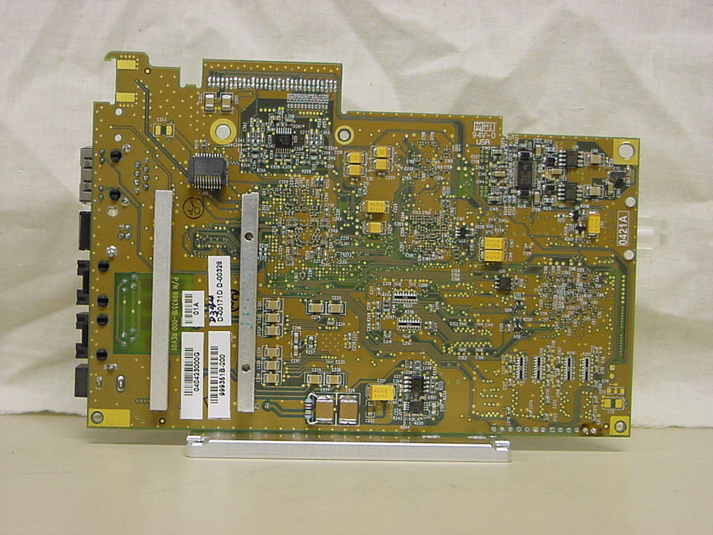
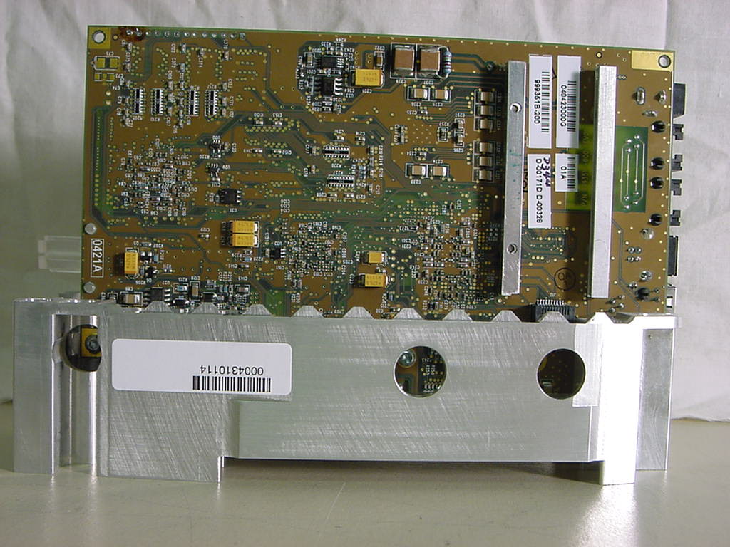
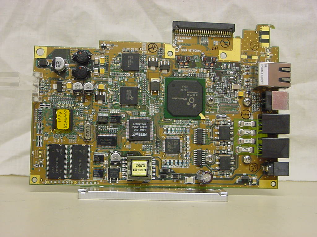
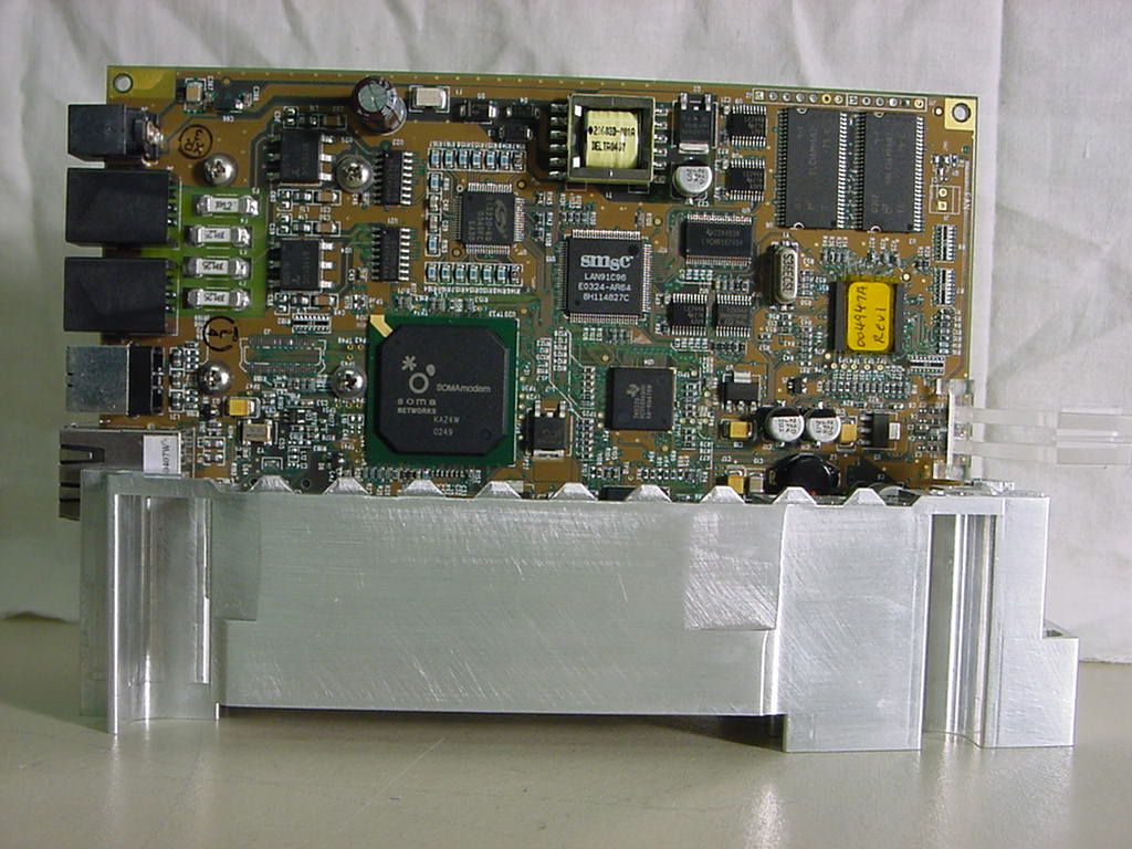
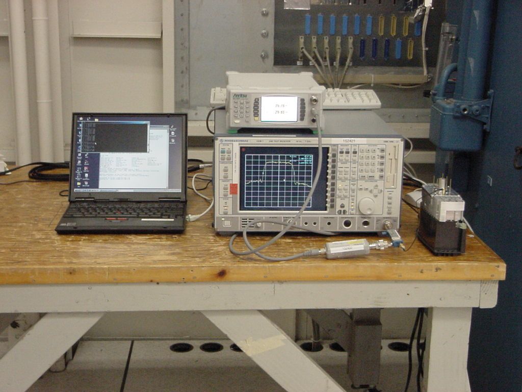
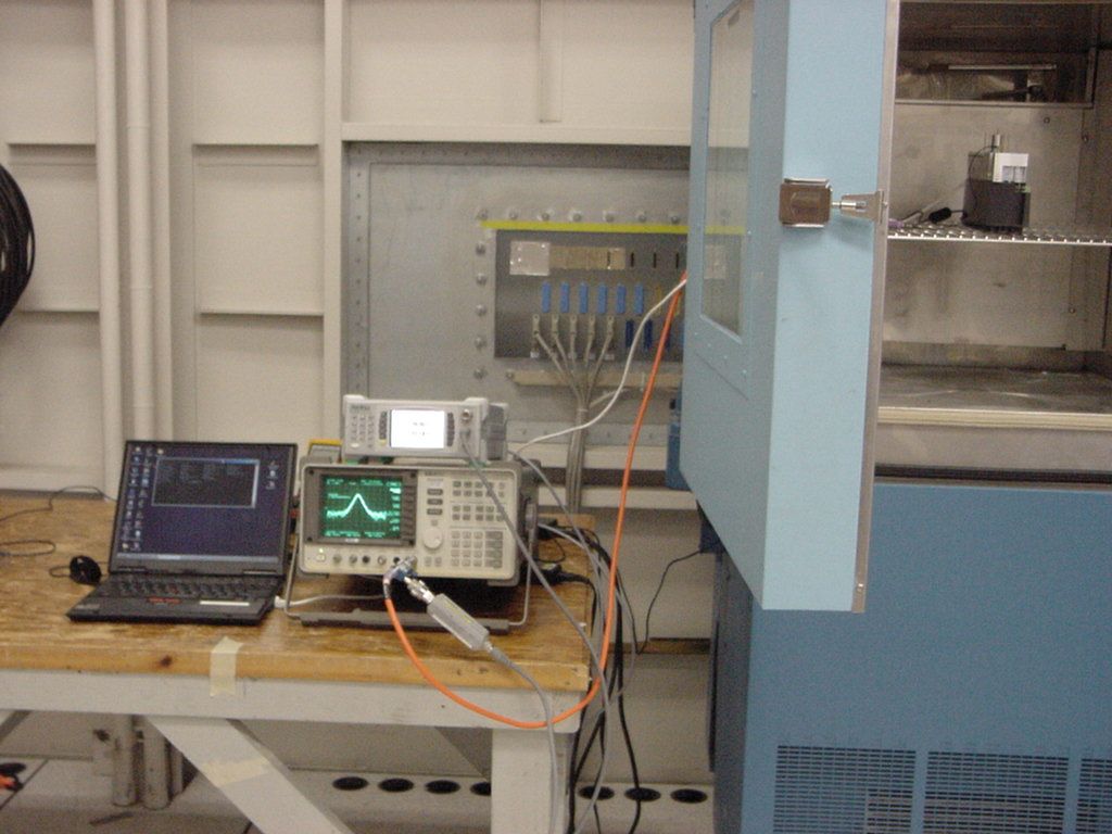
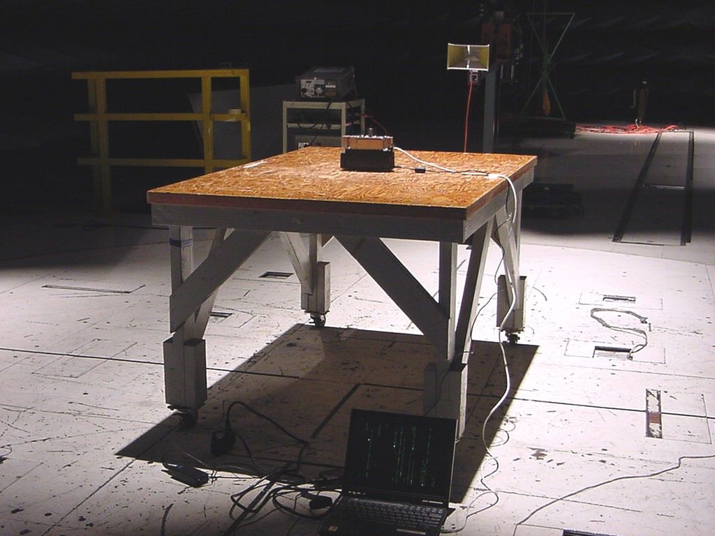
1 Chris Harvey From:Marianne Bosley [[email protected]] Sent:Tuesday, September 14, 2004 1:05 PM To:'[email protected]' Cc:Kerwinn Corpuz; Marianne Bosley; Shari Meyers Subject:Response to RT for MT15478 Soma networks. Importance:High Please see your metbox for the attachments mentioned (they'll be there soon). Question #1 (per Kerwin), please refer to page 1 of 44 "Type of Emission: 4M69F9W" of the report (attachment). Question #2 (per Kerwin), please refer to page 27 and 28 of 44 "Radiated Emission (Substitution Method)" for additional test procedure and test result of EIRP at the fundamental. Setup photo is on page 32 of 44. 3. Please provide the range of operating RF Power output and an indication if this is stepped or continually variable. ANSWER (per client): This question (both parts) is already answered in #3 of the SP3 _PCS_Technical_Questionnaire.doc provided in the package. 4. The Technical Reference states in Table 1-3 that the Typical Directive Gain in the Quadrant Mode is 4dBi. However in table 1.1 and elsewhere in the application the gain is stated as 3dBi. Please explain this discrepancy. ANSWER:(per client) This was a typo in the Tech Ref. I've attached a corrected revision of the doc. 5. There are exhibits for an MMDS Radio (Schematic and PCB Layout diagrams) that seem not to apply to this device. Please confirm if these exhibits belong with this application. ANSWER: (per client - Chris if you don't have the correct exhibit - and it's just not a matter of knowing what the MMDS exhibit is, let me know)I took a look in the ZIP package and could not find any MMDS information at all. There is MMDS information at the MET FTP site, but that is not part of this TCB submission. The only information that is pertinent to the TCB submission is in the single ZIP file I provided - everything else on the FTP site should be ignored for the purposes of the TCB filing. To make this clear, what I have done is gone to the FTP site and created a top-level directory called \TCB_Submissions. I have put the updated SP3_PCS_TCB_Package.zip into that directory. It contains the updated Tech ref, label drawing, and I have removed the Part 15.19 letter (which said that the statement could not fit on the label, since now it does). 2 I would recommend that we delete the old SP3_PCS_TCB_Package.zip immediately to avoid confusion. I do not believe I have permission to delete anything on the FTP site, so I would have to leave that to you. #6 (per Kerwin) Here are the internal photos for question #6. Please have Chris disregard the internal photos that was sent to him previously. Attachments are complete photos for Subscriber Terminal. Chris, if you need more from the ftp site I will sort through what is there tomorrow. as he states. Bottomline I know right off, he is including the 15.19 on the label, and I will remove the necessary things. Chris Harvey From: Chris Harvey [[email protected]] Sent: Monday, September 06, 2004 8:41 AM To: 'Chris Harvey'; Alvin Ilarina ([email protected]); Kerwin Corpuz ([email protected]) Cc: 'Marianne Bosley' Subject: RE: Additional Information needed for SOMA FCC ID: POZCPEPCS004886C MT#15478 Page 1 of 2 9/6/2004 Please add this one additional request to the list below: 6. The internal photographs submitted show the general construction of this device. Please provide additional internal photographs showing both sides of all PC Boards in this device. Beset regards, Chris -----Original Message----- From: Chris Harvey [mailto:[email protected]] Sent: Monday, September 06, 2004 8:37 AM To: Alvin Ilarina ([email protected]); Kerwin Corpuz ([email protected]) Cc: 'Marianne Bosley' Subject: Additional Information needed for SOMA FCC ID: POZCPEPCS004886C MT#15478 Kerwin/Alvin, I have reviewed the application for SOMA referenced above and have the following items that need to be addressed in order to continue this TCB application review: 1. The RF Power measurements in this report are stated as RF Conducted Power. Devices that have integral antennas in the FCC Pt. 24 Subpart E allocation are required to have EIRP measurements. Please submit measured EIRP using the Substitution Method of EIA/TIA 603. 2. Please provide the method of determining the 5M00F9W Emission Designator stated in the test report. Typically the measured Emission Bandwidth, not the channel bandwidth, is used to determine the first 4 characters. 3. Please provide the range of operating RF Power output and an indication if this is stepped or continually variable. 4. The Technical Reference states in Table 1-3 that the Typical Directive Gain in the Quadrant Mode is 4dBi. However in table 1.1 and elsewhere in the application the gain is stated as 3dBi. Please explain this discrepancy. 5. There are exhibits for an MMDS Radio (Schematic and PCB Layout diagrams) that seem not to apply to this device. Please confirm if these exhibits belong with this application. The following items are only for informational purposes: SOMA has provided a 15.19 declaration letter, which does not belong in the Certification application package; however their claim that this device is too small to place the 2 part statement label is not in accordance with FCC policy. I am removing this from the application; however they should be placing this label on this device since FCC Pt. 15 is applicable to all the digital portions. There are 2 exhibits for MPE, one in the report using the measured RF Conducted power and one using the estimated /rated +27dBm RF power. Since the stand-alone MPE exhibit uses the incorrect RF Power, I will remove this from the application and use the MPE Exhibit in the report. If the Antenna Gain determination above is different than the 3dBi stated, please revise the MPE exhibit accordingly. Please provide all the responses together and directly to me and copy Marianne. Please contact me if you have any questions. Best regards, Chris Harvey [email protected] Page 2 of 2 9/6/2004
Cover Letter(s)
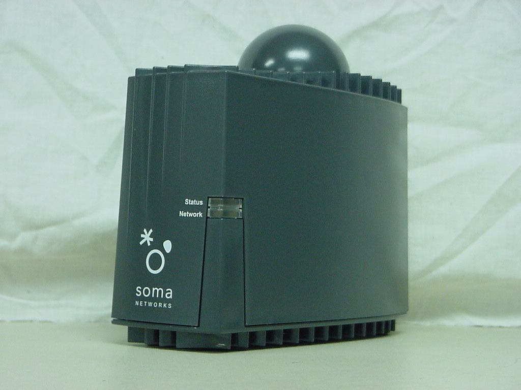
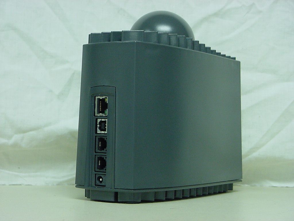
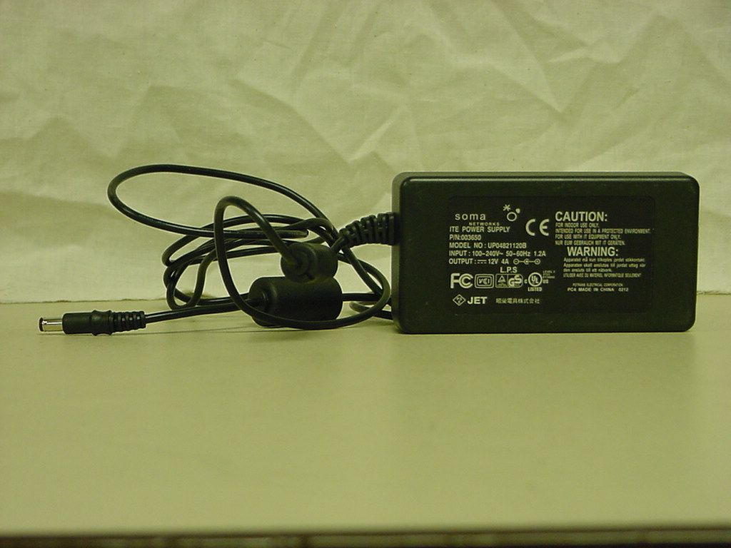
FCC Home | Search | Updates | E-Filing | Initiatives | For Consumers | Find People Office of Engineering and Technology FCC > FCC E-filing > TCB > List/Modify Exhibits FCC Site Map The following list contains all exhibits currently on file for the application: Confirmation Number: tc347746 FCC ID: POZCPEPCS004886C Exhibit Type File Type File Size Description Submission Date Standard Confidentiality Short-Term Confidentiality Supercede Cover Letter(s)PDF10619 RT10/30/2004 YN YNYN Cover Letter(s)PDF17062 RT Response10/30/2004 YN YNYN Cover Letter(s)PDF62974 confidentiality letter10/30/2004 YN YNYN Cover Letter(s)PDF48600 agent authorization letter 10/30/2004 YN YNYN External PhotosJPG124702 AC DC Adapter10/30/2004 YN YNYN External PhotosJPG132832 rear left side10/30/2004 YN YNYN External PhotosJPG132800 front right side10/30/2004 YN YNYN ID Label/Location Info PDF89025 1519 statement10/30/2004 YN YNYN ID Label/Location Info PDF222818 label and location10/30/2004 YN YNYN Internal PhotosJPG129899 inside of chassis10/30/2004 YN YNYN Internal PhotosJPG131130 RF board top side10/30/2004 YN YNYN Internal PhotosJPG128605 RF board bottom side10/30/2004 YN YNYN Internal PhotosJPG127247 digital board top side10/30/2004 YN YNYN Internal PhotosJPG127514 digital board bottom side 10/30/2004 YN YNYN Internal PhotosJPG129022 digital board bottom with part chassis 10/30/2004 YN YNYN Internal PhotosJPG130269 digital board top side with part chassis 10/30/2004 YN YNYN Operational Description PDF599002 technical reference10/30/2004 YN YNYN Parts List/Tune Up Info XLS70657 BOM10/30/2004 YN YNYN Parts List/Tune Up Info PDF88720 tuneup10/30/2004 YN YNYN RF Exposure Info PDF115717 MPE letter10/30/2004 YN YNYN SchematicsPDF3113279schematics10/30/2004 YN YNYN SchematicsPDF3464347schematics baseband and RF boards 10/30/2004 YN YNYN Test ReportDOC 27137 21033 info10/30/2004 YN YNYN Test ReportPDF1346348test report10/30/2004 YN YNYN Test Setup Photos JPG156280 radiated spurious setup 10/30/2004 YN YNYN Test Setup Photos JPG136208 frequency stability setup 10/30/2004 YN YNYN Test Setup Photos JPG159372substitution method setup 10/30/2004 YN YNYN Test Setup Photos JPG132725 conducted measurement setup 10/30/2004 YN YNYN Users ManualPDF1816988user manual10/30/2004 YN YNYN ContinueClear Last Reviewed/Updated on 06/15/2003 Please send any comments or suggestions for this site to OET Systems Support Federal Communications Commission 445 12th Street, SW Washington, DC 20554 More FCC Contact Information... Phone: 888-CALL-FCC (225-5322) TTY: 888-TELL-FCC (835-5322) Fax: 202-418-0232 E-mail: [email protected] - Web Policies & Privacy Statement - Customer Service Standards - Freedom of Information Act
ID Label/Location Info
4.900 1.100 .860 1.026 R.050 TYP .838 DRAWING SCALE 2:1 4 5 6 7 8 7 7 10 12 3 13 REMOVE FCC LOGO 14 D C A A B C D 1 3 4 5 678 8 7 65 4 3 2 1 THE INFORMATION CONTAINED IN THIS DRAWING IS THE SOLE PROPERTY OF SOMA NETWORKS, INC. ANY REPRODUCTION IN PART OR AS A WHOLE WITHOUT THE WRITTEN PERMISSION OF SOMA NETWORKS IS PROHIBITED. PROPRIETARY AND CONFIDENTIAL MATERIAL: FINISH: DRAWN DATE NAME TITLE: SIZE B DWG. NO. REV SHEET 1 OF 1 SCALE: 1:1 REVISIONS REV.COMMENT UNLESS OTHERWISE SPECIFIED: DO NOT SCALE DRAWING LABEL,REGULATORY,USA,SP3,PCS [SOMAPORT 300 MODEL CPE-300-200],PRE-PRINTED 004888A 03 thnguyen DIMENSIONS ARE IN INCHES TOLERANCES: ANGULAR: 1 ONE PLACE DECIMAL .1 TWO PLACE DECIMAL .01 THREE PLACE DECIMAL .005 DWG. NO. REV SH 004888A 03 1 02 RELEASE PER EC-03364. 9/8/2004 9/8/2004 ENG APPR. MODEL FILE: 004888A.SLDPRT/REV01 9 01 RELEASE PER EC-03359 ; CHANGES NOTED WITH RELEASE PER EC-03427 03 1. MARK VENDOR NAME, LABEL DESIGNATION, AND SOMA NETWORKS PART NUMBER ON EACH SHEET OF LABELS. 2. BACKGROUND TO BE DARK GRAY (PANTONE COLOR 432C) LETTERING AND GRAPHICS TO BE SILVER. 3. REFER TO APPROPRIATE AGENCY LISTING MARK INFORMATION TO REPLACE REFERENCE SYMBOLS WITH APPROPRIATE REGISTERED MARKS. 4. FONT: ARIAL 24 POINT 5. FONT: ARIAL NARROW 18 POINT 6. FONT: ARIAL 10 POINT 7. FONT: ARIAL 6 POINT 8. FONT: ARIAL 5 POINT 9. LABEL CONSTRUCTION TO CONSIST OF A 0.010" THICK POLYCARBONATE LABEL STOCK WITH A 0.002" THICK 3M #467 PRESSURE SENSITIVE ADHESIVE. SOMA ENGINEERING APPROVED MATERIALS MAY BE SUBSTITUTED. LABEL MUST BE A COMPONENT MARKING AND LABELING SYSTEM APPROVED BY UL AND CSA FOR THE FOLLOWING CONDITIONS: A) INDOOR B) TEMPERATURE RANGE: -40C TO +55C WHEN AFFIXED TO GE CYCOLOY C6200 (PC/ABS BLEND) 10. PRINT “FCC ID: POZCPEPCS004886C” AT NOTED LOCATION. 11. NOT USE. 12. PRINT “LISTING # E112355” AT NOTED LOCATION. 13. PLACE MET LOGO (MET1US.GIF) IN NOTED LOCATION. 14. FONT: ARIAL NARROW 6 POINT 8 4 PLACES 2 2 3 4 5 12 1 3 3 3 5 5 5 5 6 4 EXPLODED VIEW 9 10 7 7 ASSEMBLED VIEW D C A A B C D 1 345678 8 7 654321 THE INFORMATION CONTAINED IN THIS DRAWING IS THE SOLE PROPERTY OF SOMA NETWORKS, INC. ANY REPRODUCTION IN PART OR AS A WHOLE WITHOUT THE WRITTEN PERMISSION OF SOMA NETWORKS IS PROHIBITED. PROPRIETARY AND CONFIDENTIAL MATERIAL: FINISH: DRAWN DATE NAME TITLE: SIZE B DWG. NO. REV SHEET 1 OF 1 SCALE: 1:3 REVISIONS REV.COMMENT UNLESS OTHERWISE SPECIFIED: DO NOT SCALE DRAWING ASSY DWG MX,SYSTEM,SP3 ADM-000057 thnguyen DIMENSIONS ARE IN INCHES TOLERANCES: ANGULAR: 1 ONE PLACE DECIMAL .1 TWO PLACE DECIMAL .01 THREE PLACE DECIMAL .005 DWG. NO. REV SH ADM-000057 1 8/12/2004 8/12/2004 bbonn ENG APPR. MODEL FILE: SP3_ASM_TRI.SLDPRT/REV05 01 01 01 INITIAL RELEASE PER EC-03353 NOTES: (UNLESS OTHERWISE SPECIFIED) 1. ASSEMBLE UNIT PER INSTRUCTIONS BELOW (NOTES 2-7): 2. TORQUE SCREW, ITEM 8, TO 8±1 IN-LBS. 3. ASSEMBLE ITEMS 4 AND 5, EMI CONTACTS TO RIGHT AND LEFT, INTO PINS OF THE ITEM 2, BOTTOM CASE. PRESS DOWN UNTIL SURFACES MEET. 4. SLIDE ITEM 1, CHASSIS/PCA ASSEMBLY, INTO ITEM 2, BOTTOM CASE. FOUR HOLES IN ITEM 1 ALIGN WITH HOLES IN ITEM 2. 5. PLACE ITEM 3, TOP CASE, OVER ITEM 2, BOTTOM CASE. ASSEMBLE ITEM 3 TO THE ITEM 1, CHASSIS/PCA ASSEMBLY, AND ITEM 2, BOTTOM CASE, USING SCREWS, ITEMS 8 (4X). 6. PLUG RUBBER FEET, ITEMS 12 (4X), INTO HOLES IN BOTTOM OF ITEM 2. PRESS IN UNTIL SURFACES MEET. 7. PLACE ITEM 9, REGULATORY LABEL, AND ITEM 10, SERIAL NUMBER LABEL, IN DETENT ON BOTTOM OF ITEM 2. LABELS TO BE APPROXIMATELY .020 IN FROM EDGE OF LABEL DETENT AND APPROXIMATELY .060 IN FROM EACH OTHER.
ID Label/Location Info
SOMA Networks, Inc. 185 Berry Street, Suite 4600 ◦ San Francisco, California 94107 185 Berry Street • Suite 4600 • San Francisco CA 94107 • Phone: 415.882.6500 • Fax: 415.882.6512 August 13, 2004 ATTN: Reviewing Engineer Federal Communications Commission 7435 Oakland Mills Road Columbia, MD 21046 RE: Part 15.19 label for SOMAport3, Model # CPE-300-200, FCC ID: POZCPEPCS004886C To Whom It May Concern: The product label on the SOMA Model number CPE-300-200 is too small to fit the declaratory statement in Part 15.19. This declaration has been included in the User Manual. Sincerely, Robin Grindley Chief Scientist – Hardware Systems SOMA Networks, Inc.
RF Exposure Info
SOMA Networks, Inc. 185 Berry Street, Suite 4600 ◦ San Francisco, California 94107 185 Berry Street • Suite 4600 • San Francisco CA 94107 • Phone: 415.882.6500 • Fax: 415.882.6512 August 13, 2004 ATTN: Reviewing Engineer Federal Communications Commission 7435 Oakland Mills Road Columbia, MD 21046 RE: MPE Calculation for SOMAport3, Model # CPE-300-200, FCC ID: POZCPEPCS004886C To Whom It May Concern: The RF exposure limits for radio transmitters are given in 47 CFR 1.1310. The EUT operates at 1850-1910 MHz and is intended for home use. Therefore the applicable exposure limits are in Table 1, section B (for General Population/Uncontrolled Exposure). The applicable Power Density limit for 1500-100,000 MHz from Table 1 is: 1 mW/cm 2 The CPE-300-200 is intended for use at distances of >20cm from the user, and this safety requirement is explicitly stated in the user manual. The CPE-300-200 has the following transmitter operating parameters in the maximal case: Maximum Transmitter Power (P): +27 dBm Maximum Numerical Antenna Gain (G): +5 dBi As per FCC Bulletin 65, the formula used to calculate the exposure level, S (in mW/cm 2 ) at a distance R=20 cm is: 2 5026 16.3501 4 /315.0 22 cmmWS cm mW R PG === × π Thus the CPE-300-200 is below the MPE limit of 1 mW/cm 2 at a distance of 20 cm. Sincerely, Robin Grindley Chief Scientist – Hardware Systems SOMA Networks, Inc.
Test Report
DOC-FCC007-4C 2/19/04 Page 1 of 1 FCC GRANT OF EQUIPMENT AUTHORIZATION APPLICATION ALL RULE PARTS OTHER THAN 11, 15, AND 18 (PLEASE COMPLETE QUESTIONAIRE) 1. Type or types of emissions: Direct-sequence spread-spectrum 2. Frequency Range: 1850-1910 MHz 3. Range of operating power values or specific operating power levels, and description of any means provided for variation of operating power: The RF transmit power is controlled over a range of -45dBm to +27dBm, measured at the antenna terminals. The method of controlling the power involves variable gain control elements in both the IF and RF paths. The power level is monitored by a detector on the output of the final amplifier and an active hardware control loop limits the maximum power, at the antenna, to +27dBm. The detector is factory calibrated and cannot be modified other than in the factory. 4. Maximum power rating as defined in the applicable rule part(s): +27 dBm transmit power at antenna input with +3dBi integral antenna = +30 dBm EIRP 5. dc voltages applied to and dc currents into the several elements of the final radio frequency amplifying device for normal operation over the power range The DC voltage/current into the final amplifier is 450mA @ 4.5volts at maximum transmit power.
Contact Information
Applicant
Robin Grindley(Chief Scientist-Hardware Systems)
Test Firm
MET LaboratoriesAlvin Ilarina
Technical Specifications
| # | Rule Parts | Frequency Range | Power Output | Emission | Tolerance |
|---|---|---|---|---|---|
| 1 | 24E | 1.85 GHz - 1.91 GHz | 1.75 W | 4M69F9W | 850.0000000000 Hz |
Other Applications from SOMA Networks, Inc.
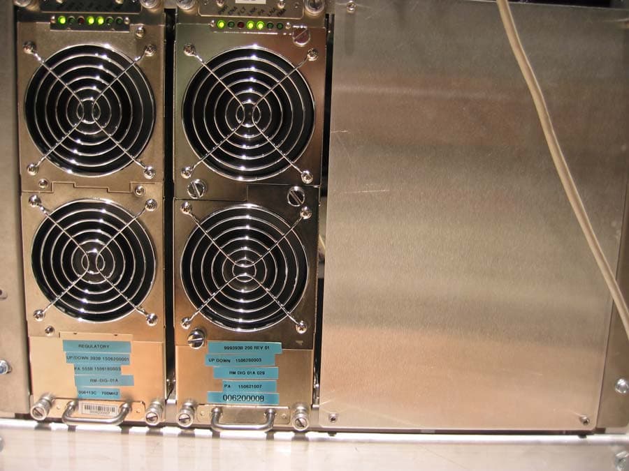
POZNPM700007168A
Sep 06, 2006FBS Wireless Base Station (NPM-2500)
Equipment Class
TNB - Licensed Non-Broadcast Station Transmitter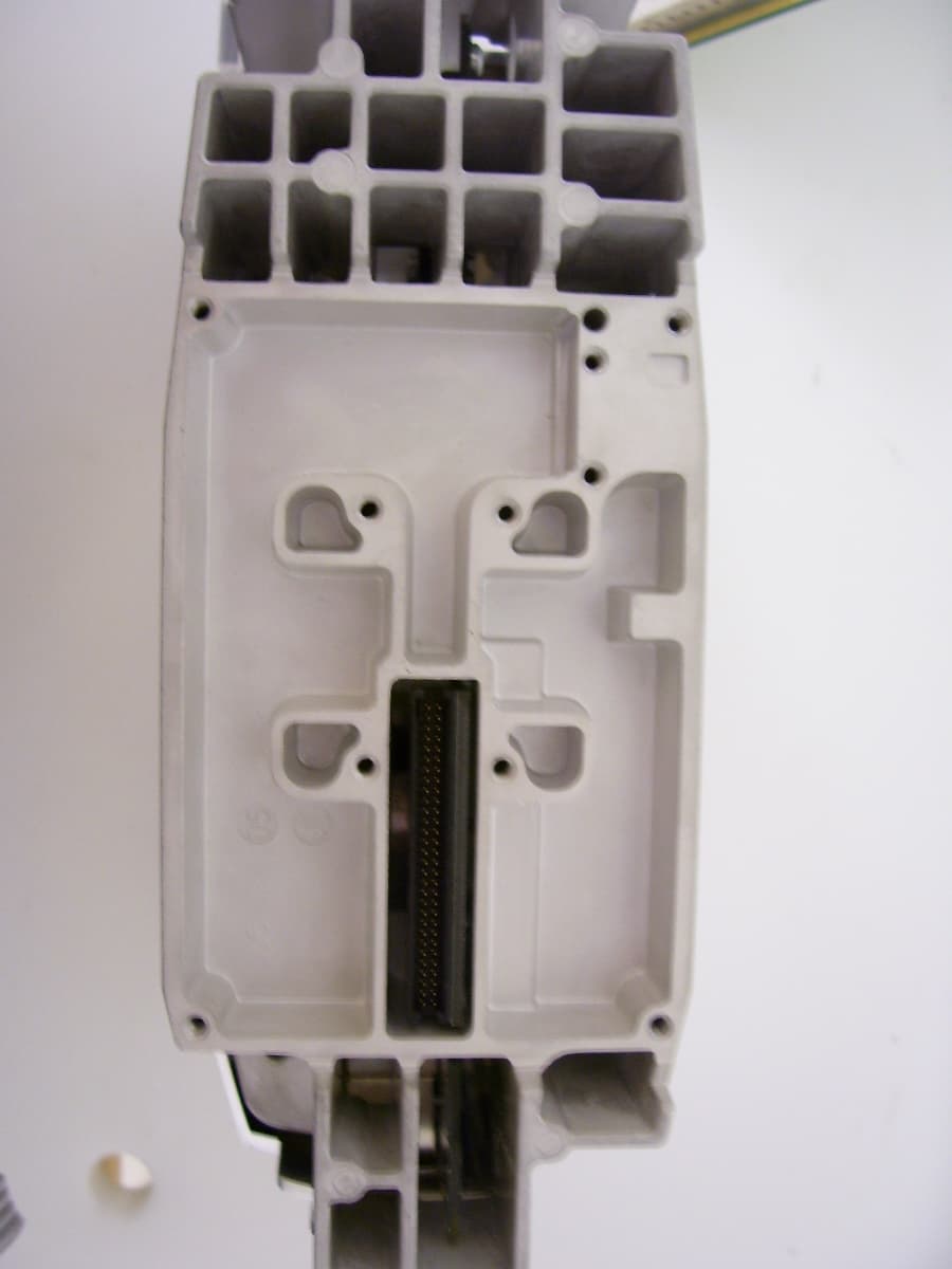
POZCPE700006553D
Aug 30, 2006CPE-300-2C0 (SOMAport Subscriber Terminal)
Equipment Class
TNB - Licensed Non-Broadcast Station Transmitter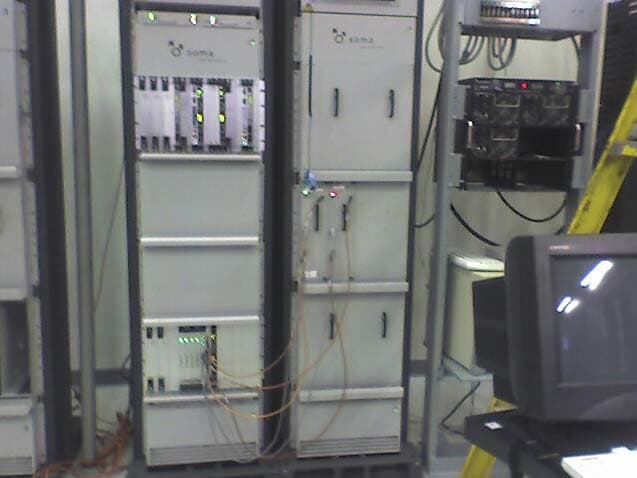
POZNPMWCS005777A
Apr 26, 2006NPM Wireless Base Station
Equipment Class
TNB - Licensed Non-Broadcast Station Transmitter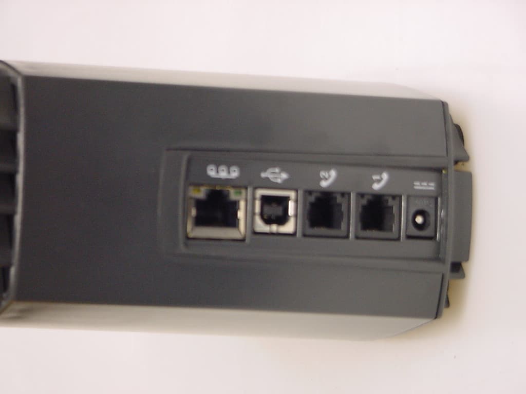
POZCPEWCS005239B
Apr 26, 2006SOMAport Subscriber wireless terminal
Equipment Class
TNB - Licensed Non-Broadcast Station Transmitter
POZNPMMDS004699
Oct 01, 2003Base Transmitter
Equipment Class
TNB - Licensed Non-Broadcast Station Transmitter