POZWAU0403110002External Radio Unit
SOMA Networks, Inc.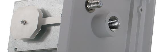
Click to zoom
Application Details
- Equipment Class
- AMP - Amplifier
- Date of Grant
- Apr 28, 2003
- Application Purpose
- Original Equipment
- Date of Application
- Apr 24, 2003
- Equipment Note
- External Radio Unit
- Frequency Range
- 2307.50000000 - 2307.50000000
- Company
- SOMA Networks, Inc.
- Country
- United States
Documents & Files
Document Text
Text extracted from the exhibit documents filed with the FCC. Open a document above to read the original.
Users Manual
NETWORKS TM TM External Radio Unit Installation Guide Release 2.0 Part 002739A revision 00d Revision History RevisionDateChanges Made 00aJanuary 15, 2003Document created based on the Release 1.0 version (revision 00e) of the Booster Antenna Installation Guide. 00bFebruary 10, 2003 Comments from technical review incorporated 00cFebruary 14, 2003 Comments from editorial review incorporated Removed references to use of a water pipe as the central building ground 00dFebruary 25, 2003 Product name changed to External Radio Unit (ERU) Added legal disclaimer to front matt er Copyright 2002, 2003 SOMA Networks, Inc. All Rights Reserved. SOMA Networks, Inc. 185 Berry Street Suite 2000 San Francisco, CA 94107 U.S.A. Phone +1.415.882.6500 Fax+1.415.882.6501 SOMA, SOMA Networks and the star-and-circle logo are trademarks of SOMA Networks, Inc. All SOMA Networks product names are trademarks of SOMA Networks, Inc. All other company and product names may be trademarks or registered trademarks of their respective owners. Products and services of SOMA Networks, Inc. may be protected by one or more pending or issued U.S. or foreign patents. A list of third-party software used in the production of or included in this product, as well as any available documentation for such software, can be obtained at www.somanetworks.com/thirdparty.html. SOMA Networks, Inc. assumes no responsibility for the accuracy or completeness of the information presented or for any use of the information contained in this document. SOMA Networks, Inc. reserves the right to, without notice, make changes to its products as progress in engineering or manufacturing methods or circumstances may warrant. 3 Important Notice An improperly installed ERU may cause serious damage to you and/or your property or may even cause fatal injuries. The External Radio Unit Installation Guide has been developed and is intended for those individuals with experience in performing various installation tasks involving outdoor telecommunication devices. It is strongly recommended that the ERU be installed by those individuals who have experience, at a minimum, with the following tasks: Familiarity and ability to use a power drill and associated tools and devices to safely drill holes into the exterior and interior structures of a house Familiarity and ability to determine with a high degree of accuracy and precision the location of support studs, water pipes, electrical wiring, or heating, air conditioning or gas lines or conduits in the structure near where holes are being drilled in the house Familiarity and ability to route coaxial cables through walls, under floors and/or interior walls, and if necessary, to safely cut coaxial cables and incorporate any necessary weatherproofing techniques Familiarity with the National Electrical Code (NEC) (published by the National Fire Protection Association), the Canadian Electrical Code (CEC), or the electrical code of your country, to have sufficient ability to ground the ERU in accordance with the national electrical code recommendations at the time of the publication of the External Radio Unit Installation Guide By undertaking to install the ERU by yourself, you are assuming full responsibility that your building and roof are structurally sound to support the load (including weight, wind, water and ice, in addition to your weight) in the process of installation of the ERU, that you are capable of sealing the installation against all leaks, that you have consulted with the latest applicable version of the national electrical codes of your country (NEC, CEC, or other) and that you have read and understood the contents of the External Radio Unit Installation Guide, including all safety precautions and alerts as provided at the beginning of, and throughout, the External Radio Unit Installation Guide. Any failure on your part to follow the safety precautions and alerts may cause serious injury, fatal injuries, damage to property and/or void any warranty provided by your service provider. Before installing the ERU, you are advised to check the zoning codes, covenants and community restrictions that may be applicable in your area. Certain areas may prohibit the installation of devices such as the ERU. 4 SOMA Networks, Inc. will not accept and is not responsible or liable for any damages or injuries that may result from the installation of the ERU by you. If you are not in agreement with this notice, or do not have the experience necessary to install the ERU, please contact your telecommunications service provider for further instructions with regard to the proper installation of the ERU. 5 Preface This document describes how to install the External Radio Unit (ERU), ground it, and connect it to the SOMAport. Related Documentation The following table lists the SOMA Networks consumer documents that cover SOMAport installation Conventions This section outlines the conventions used in this guide. Measurement Conventions Measurements in this guide are expressed according to the Systeme International d’Unites standards for metric units and abbreviation. Equivalent Imperial measurements (used in the United States) are provided in parentheses, except when Imperial is the international standard. Bits and bytes are not abbreviated, though their prefixes are; for example, “kbits” for kilobits, “Gbytes” for gigabytes. DocumentDescriptionAudience SOMAport Setup GuideInstallation and maintenance guide for the SOMAport Subscribers SOMAport Quick Setup Card Quick installation cardSubscribers 6 Trademark Identification The SOMAport TM subscriber device, a trademark of SOMA Networks, Inc., is referred to without notation in the rest of this document. Tell Us How We Are Doing If you have any feedback about this document, e-mail Technical Communications at SOMA Networks: [email protected]. Alerts used in this guide WARNING: Where you see this symbol and the WARNING heading, strictly follow the instructions to avoid pe…
Text truncated - open the document above for the full version.
Cover Letter(s)
Page 1 of 1 Soma Networks RE: FCC ID: POZWAU0403110002 1) Please explain the use of DoC labeling on the device. Due to the frequency of the RX, it is not regulated under Part 15 nor does the device directly attach to a computer and is therefore not a PC peripheral device. If a DoC authorization is not appropriate for this device, please remove this information from the labeling (FCC logo, FOR HOME OR OFFICE USE, etc.) Response: The FCC logo and statement were not supposed to be on the label. A revised label has been uploaded that does not include these elements. 2) The theory of operations did not contain the tune-up procedures as specified by the test report. Note that if the tune-up procedure appears to contain confidential information, confidentiality was not requested on this exhibit. Please confirm if confidentiality is desired and update the confidentiality letter if necessary. Response: The theory of operations document has been revised to add the tune up procedure. This document has been uploaded. 3) The theory of operations/Block Diagram state that the TX frequency is 2307.5 MHz, while the 731/Test Report (page 6 & 10 of 21) states 2306 MHz. Part 27 mentions the frequency block A of 2305 - 2310 MHz. Given the emission bandwidth of 4.18 MHz and a transmission frequency of 2306, the fundamental would extend outside the allotted band of 2305-2320 MHz. Please confirm that the TX frequency is 2307.5 MHz. Additionally, page 10 of 21 of the test report mentions a TX band of 2300-2320. This information and the "guard band" mentioned here does not appear correct . Please explain. Response: Both 731 form and report have been corrected and revised. Both documents have been uploaded. 2307.5 MHz is correct. 4) Please provide test data for 2.1055. This information does not appear to have been provided. Response: Since the ERU is an external power amplifier and antenna; no frequency stability test is required. The report has been revised to state this as well. Hopefully this answers all of your questions. Please contact me [email protected] you require more information. Regards, Juan Martinez Sr. EMC Engineer
Cover Letter(s)
American Telecommunications Certification Body Inc. 6731 Whittier Ave, McLean, VA 22101 April 14, 2003 RE: SOMA Networks, Inc. FCC ID: POZWAU0403110002 I have a few comments on the above referenced Application. 1) Please explain the use of DoC labeling on the device. Due to the frequency of the RX, it is not regulated under Part 15 nor does the device directly attach to a computer and is therefore not a PC peripheral device. If a DoC authorization is not appropriate for this device, please remove this information from the labeling (FCC logo, FOR HOME OR OFFICE USE, etc.) 2) The theory of operations did not contain the tune-up procedures as specified by the test report. Note that if the tune-up procedure appears to contain confidential information, confidentiality was not requested on this exhibit. Please confirm if confidentiality is desired and update the confidentiality letter if necessary. 3) The theory of operations/Block Diagram state that the TX frequency is 2307.5 MHz, while the 731/Test Report (page 6 & 10 of 21) states 2306 MHz. Part 27 mentions the frequency block A of 2305 - 2310 MHz. Given the emission bandwidth of 4.18 MHz and a transmission frequency of 2306, the fundamental would extend outside the allotted band of 2305-2320 MHz. Please confirm that the TX frequency is 2307.5 MHz. Additionally, page 10 of 21 of the test report mentions a TX band of 2300-2320. This information and the "guard band" mentioned here does not appear correct . Please explain. 4) Please provide test data for 2.1055. This information does not appear to have been provided. Timothy R. Johnson Examining Engineer mailto: [email protected] The items indicated above must be submitted before processing can continue on the above referenced application. Failure to provide the requested information may result in application termination. Correspondence should be considered part of the permanent submission and may be viewed from the Internet after a Grant of Equipment Authorization is issued. Please do not respond to this correspondence using the email reply button. In order for your response to be processed expeditiously, you must submit your documents through the AmericanTCB.com website. Also, please note that partial responses increase processing time and should not be submitted. Any questions about the content of this correspondence should be directed to the sender.
Cover Letter(s)
American Telecommunications Certification Body Inc. 6731 Whittier Ave, McLean, VA 22101 April 21, 2003 RE: SOMA Networks, Inc. FCC ID: POZWAU0403110002 I have a few comments on the above referenced Application. 1) Regarding the Frequency Stability, you stated that a 16 MHz Oscillator that is generated from the internal previously approved indoor unit is used for stabilization of the fundamental of the outdoor unit. Reviewing the block diagram for the previously approved indoor unit, this oscillator appears to only be used for the external unit now being approved, but not for the indoor unit which was previously approved. Therefore stability of this reference oscillator has not been shown. Additionally, it is uncertain how frequency error that occurs at the 16 MHz reference oscillator translates to frequency error at the fundamental. Please provide test data for 2.1055 (-30 degrees C to +50 degrees C in 10 degree increments with adequate soak times between, also 85% - 115% variation in input voltage to the indoor unit at 20 degrees C). Note: Due to the nature of the system, it would be recommended to subject both the indoor and outdoor unit to the temperature variation. Additionally, this information may be provided by the manufacturer. Timothy R. Johnson Examining Engineer mailto: [email protected] The items indicated above must be submitted before processing can continue on the above referenced application. Failure to provide the requested information may result in application termination. Correspondence should be considered part of the permanent submission and may be viewed from the Internet after a Grant of Equipment Authorization is issued. Please do not respond to this correspondence using the email reply button. In order for your response to be processed expeditiously, you must submit your documents through the AmericanTCB.com website. Also, please note that partial responses increase processing time and should not be submitted. Any questions about the content of this correspondence should be directed to the sender.
Cover Letter(s)
Page 1 of 2 Tim Johnson American TCB April 24, 2003 RE: FCC ID: POZWAU0403110002 Dear Tim, In your latest correspondence you asked for the following information: 1) Regarding the Frequency Stability, you stated that a 16 MHz Oscillator that is generated from the internal previously approved indoor unit is used for stabilization of the fundamental of the outdoor unit. Reviewing the block diagram for the previously approved indoor unit, this oscillator appears to only be used for the external unit now being approved, but not for the indoor unit which was previously approved. Therefore stability of this reference oscillator has not been shown. Additionally, it is uncertain how frequency error that occurs at the 16 MHz reference oscillator translates to frequency error at the fundamental. Please provide test data for 2.1055 (-30 degrees C to +50 degrees C in 10 degree increments with adequate soak times between, also 85% - 115% variation in input voltage to the indoor unit at 20 degrees C). Note: Due to the nature of the system, it would be recommended to subject both the indoor and outdoor unit to the temperature variation. Additionally, this information may be provided by the manufacturer. In response, Soma have provided the following information: The transmit fundamental frequency is set by a phase locked loop (synthesizer) that is phase locked to the external 16MHz reference oscillator. The chain of referencing is the following: the internal 16MHz is locked to the base station (oven/GPS stabilized <<0.1ppm), the external 16MHz is phase locked to the internal 16MHz oscillator, the transmit LO is phase locked to the external 16MHz oscillator. Thus, the SAU transmit frequency is precisely controlled by the Base Station’s transmitted signal and is better than +/-0.1ppm. The transmit frequency is 2307.5MHz thus the frequency error is less than +/-231 Hz. The SAU cannot start to transmit until it has locked on to a base station and therefore is dependent on the accuracy of the signal transmitted by the Base Station to determine the stability of its transmission. As the base station is already approved by the FCC and frequency stability for the base station directly affects that of the SAU, Soma do not consider it necessary to evaluate the stability of the SAU over the temperature extremes. Page 2 of 2 Hopefully this answers the requirements for demonstrating frequency stability without having to perform stability tests on the SAU, and would appreciate your comments on this. Please contact me via [email protected] if you require more information. Regards, for Juan Martinez Sr. EMC Engineer
External Photos
Exterior and Interior Photographs Soma ERU Page 1 of 8 Pages Exterior Photograph Interior Photographs
ID Label/Location Info
ACCESSORY UNIT Model: AU-100-130 CAUTION: FOR OUTDOOR USE ONLY! USE ONLY WITH COMPATIBLE SOMAport. FOR HOME OR OFFICE USE Made in U.S.A. label pn 004230A Rev01 FCC ID: POZWAU0403110002 U L CUS LISTED ITE 91LF E217858 S/N: This device complies with Part 15 of FCC Rules. Operation is subject to the following two conditions: (1) this device may not cause harmful interference, and (2) this device must accept any interference received, including interference that may cause undesired operation.
ID Label/Location Info
3 1 4 5 6 (8X) (8X) (8X) .10 .05 9 D C A A B C D 1 2345678 87 654 3 2 1 TITLE: SIZE B DWG. NO. REV SHEET 2 OF 2 SCALE: 1:1 ADM-000028 01 DWG. NO. REV SH ADM-000028 01 2 ASSY DWG,ERU,SP,PCS,Rel 2
Internal Photos
Page 3 of 8 Pages Page 4 of 8 Pages Page 5 of 8 Pages Page 6 of 8 Pages Page 7 of 8 Pages Page 8 of 8 Pages
Parts List/Tune Up Info
Level Item Number Item Description Rev Line Num Qty Ref Des BOM Notes 0 999300A-200 PCA,ERU,RF,WCS-A 01A 1 999300A-000 PCB,ERU,RF,WCS-A 01A 1 1 PCB 1 000031-0R00 RES,SMD,0R,0603 A21 R76 1 000031-220R RES,SMD,220R,5%,0603 A31 R188 1 000031-270R RES,SMD,270R,5%,0603 A41 R108 1 000035-100R RES,SMD,100R,1%,0603 A55 R85,R106,R107,R109,R110 1 000038-33R0 RES,SMD,33.0R,5%,0603 B62 R33,R263 1 000039-10R0 RES,SMD,10.0R,1%,0603 A73 R34,R47,R267 1 000039-1K82 RES,SMD,1.82K,1%,0603 A82 R203,R204 1 000039-1M00 RES,SMD,1.00M,1%,0603 A91 R236 1 000039-24K9 RES,SMD,24.9K,1%,0603 A101 R126 1 000039-4K99 RES,SMD,4.99K,1%,0603 A121 R56 1 000080-220P CAP,CER_NPO,SMD,220PF,50V,5%,0603 A131 C116 1 000080-22P0 CAP,CER_NPO,SMD,22PF,50V,5%,0603 A144 C147,C154,C159,C164 1 000080-33P0 CAP,CER_NPO,SMD,33PF,50V,5%,0603 A1521 C98,C99,C100,C101,C102,C103,C104,C105,C106,C107,C108,C109,C110,C111,C112,C113,C114,C304,C305,C309,C310 1 000081-102 CAP,CER_X7R,SMD,1000PF,50V,10%,0603 A1621 C19,C22,C28,C31,C39,C62,C146,C153,C158,C163,C167,C168,C169,C170,C194,C200,C231,C303,C307,C320,C326 1 000081-104 CAP,CER_X7R,SMD,0.1UF,16V,10%,0603 A1747 C1,C3,C4,C5,C6,C8,C9,C10,C18,C23,C25,C32,C37,C38,C40,C48,C54,C55,C57,C59,C60,C66,C68,C74,C94,C96,C120,C122,C126,C127,C128,C142,C143,C176,C234,C241,C249,C250,C252,C254,C256,C261,C295,C301,C324,C330,C332 1 000081-10N0 CAP,CER_X7R,SMD,0.01UF,50V,10%,0603 B1815 C2,C35,C41,C58,C76,C79,C81,C123,C244,C253,C255,C257,C318,C319,C321 1 000091-10U0 CAP,TAN,SMD,10UF,16V,20%,3528 A198 C15,C21,C36,C53,C121,C242,C302,C312 1 000095-47U0 CAP,TAN,SMD,47UF,10V,10%,6032 A202 C7,C49 1 000129-000 XTAL,20MHZ,20PF LOAD CAP,50PPM,5MM TALL A211 Y1 1 000182-000 HDR,TEST,8 PIN,2X4,0.1 IN,SMT A221 J3 1 000327-000 XSTR,NPN,SMT,SOT23 A231 Q17 1 000334-000 DIODE,PMBD914,SOT23 A2415 D1,D2,D4,D6,D20,D21,D22,D23,D24,D25,D26,D27,D28,D31,D32 1 000365-5N10 IND,RF,CER CHIP,WINDING,UNSHIELDED,5.1NH,2%,20 MIN Q,5.7GHZ MIN SRF,700MA RMS MAX,SMD,0603 A261 L62 1 000374-000 XSTR,NPN,MMBT3904LT1,SOT23 A272 Q8,Q20 1 000393-000 IC,AMP,RF,3.2 GHZ BW,14.9 DB GAIN, 14.7 DBM OUTPUT,SINGLE SUPPLY,SMD,4 PINS A282 U22,U29 1 000397-000 MOSFET,P-CH,1.25W,2.5V,SOT23 A291 Q18 1 000482-000 XSTR,PNP,SILICON,GENERAL PURPOSE,3906,SOT-23 A306 Q3,Q4,Q5,Q6,Q7,Q11 1 000555-000 IC,MAX2362,QUADRATURE TRANSMITTER,TQFP-EP48 A321 U12 1 000560-000 XSTR,NPN,SILICON,100 MA IC MAX,1.4 DB@ 1.0 GHZ NF,M03 A335 Q9,Q13,Q14,Q15,Q16 1 000571-000 CAP,CER_X5R,SMD,22UF,10V,20%,1812 A354 C12,C34,C51,C129 1 000626-000 CAP,CER_X7R,SMD,0.1UF,50V,20%,0805 A362 C47,C189 1 000646-000 RES,SMD,100K,1%,0603 A373 R205,R221,R228 1 000652-000 RES,SMD,3.32K,1%,0603 A381 R266 1 000710-000 IND,RF,CER CHIP,WINDING,UNSHIELDED,4.7NH,2%,20 MIN Q,5.8GHZ MIN SRF,700MA RMS MAX,SMD,0603 A391 L63 1 000712-000 RES,SMD,15.0K,1%,0603 A402 R105,R140 1 000738-000 RES,SMD,0.47R,1%,0805,1/16W A433 R202,R208,R483 1 000749-000 RES,SMD,2.20R,5%,0603 A451 R261 1 000987-000 CAP,CER_NPO,SMD,1.8PF,250V,+/-0.1PF,0603,LOW ESR A462 C239,C247 1 001154-000 CAP,CER_X7R,SMD,0.001UF,200V,10%,0805 A491 C183 1 001255-000 RES,SMD,32.4K,1%,0603 A511 R218 1 001302-000 IND,SMD,33NH,5%,0603 A525 L14,L15,L18,L21,L22 1 001303-000 IND,SMD,18NH,5%,0603 A536 L5,L12,L27,L28,L29,L30 1 001307-000 DIODE,3X SMALL SIGNAL SI A541 D5 1 001308-000 IC,DUAL COMPARATOR A551 U1 1 001310-000 IC,NAND GATE,2-INPUT,QUAD,HCMOS,SOIC-14 A571 U14 1 001321-000 RES,SMD,10M,5%,0603 A591 R79 1 001364-000 IC,QUAD,RAIL-TO-RAIL,LOW POWER OP AMP A611 U24 1 001365-000 RES,SMD,16.5K,1%,0603 A621 R129 1 001380-000 IND,SMD,27NH,5%,0603 A634 L24,L59,L60,L66 1 001420-000 IC,DECODER/DEMULTIPLEXER,HCMOS,SOIC-16 A651 U6 1 001421-000 XSTR,MICROWAVE NPN A662 Q2,Q21 1 001464-000 AMP,3 WATT GAAS HJFET A691 Q1 1 001535-000 CLIP,SMIT SHIELD A704 J2,J4,J5,J6 1 001613-000 RES,SMD,10.0R,1%,0402 A716 R35,R97,R118,R134,R138,R142 1 001672-000 RES,SMD,0R,0402 A731 R481 1 001673-000 RES,SMD,10.0K,1%,0402 A7437 R2,R8,R9,R10,R11,R12,R13,R14,R15,R16,R17,R18,R19,R31,R38,R54,R65,R81,R82,R87,R101,R113,R115,R116,R155,R158,R161,R164,R180,R183,R186,R212,R224,R229,R230,R234,R248 1 001998-000 CAP,CER_NPO,SMD,3.9PF,16V,+/-0.1PF,0402,LOW ESR A772 C201,C207 1 002004-000 CAP,CER_NPO,SMD,6.8PF,16V,+/-0.1PF,0402,LOW ESR A792 C299,C337 1 002006-000 CAP,CER_NPO,SMD,8.2PF,16V,+/-0.1PF,0402,LOW ESR A803 C203,C208,C209 1 002008-000 CAP,CER_NPO,SMD,10PF,16V,2%,0402,LOW ESR A811 C322 1 002021-000 IND,RF,MONO CHIP,AIR CORE,WINDING,SHIELDED,3.3NH,+/-0.3NH,8MIN Q,6000MHZ MIN SRF,300MA RMS MAX,0402 A822 L61,L67 1 002023-000 IND,RF,MONO CHIP,AIR CORE,WINDING,SHIELDED,4.7NH,+/-0.3NH,8MIN Q,6000MHZ MIN SRF,300MA RMS MAX,0402 A831 L70 1 002024-000 IND,RF,MONO CHIP,AIR CORE,WINDING,SHIELDED,5.6NH,+/-0.3NH,8MIN Q,5300MHZ MIN SRF,300MA RMS MAX,0402 A842 L68,L78 1 002039-000 RES,SMD,18R,5%,0402 A855 R59,R252,R254,R256,R480 1 002040-000 RES,SMD,20R,5%,0402 A866 R144,R145,R146,R147,R148,R206 1 002044-000 RES,SMD,30R,5%,0402 A882 R104,R172 1 002046-000 RES,SMD,39R,5%,0402 A892 R250,R251 1 002053-000 RES,SMD,75R,5%,0402 A911 R170 1 002054-000 RES,SMD,82R,5%,0402 A921 R257 1 002059-000 RES,SMD,150R,1%,0402 A941 R171 1 002060-000 RES,SMD,160R,1%,0402 A952 R262,R264 1 002066-000 RES,SMD,300R,1%,0402 A964 R26,R57,R58,R149 1 002067-000 RES,SMD,330R,1%,0402 A972 R189,R190 1 002068-000 RES,SMD,360R,1%,0402 A982 R167,R168 1 002071-000 RES,SMD,470R,1%,0402 A 100 2 R20,R21 1 002072-000 RES,SMD,510R,1%,0402 A 101 2 R88,R150 1 002155-000 CAP,CER_NPO,SMD,1.5PF,25V,+/-0.1PF,0402,LOW ESR A 105 4 C259,C300,C311,C329 1 002162-000 CAP,CER_NPO,SMD,2.2PF,25V,+/-0.1PF,0402,LOW ESR A 106 2 C313,C314 1 002176-000 CAP,CER_NPO,SMD,6.8PF,25V,+/-0.1PF,0402,LOW ESR A 108 1 C202 1 002252-000 OSC,VC-TCXO,SMD,16MHZ,2.5PPM,3.0V SUPPLY,0.8V MIN. P-P SINEWAVE OUTPUT,3X5MM A 109 1 U19 1 2261 FILTER,SAW,190 MHZ CF,2.5 MHZ MIN 1DB-BW,7 DB MAX IL,SMD-6P,5.0X3.2X1.4 MM A 110 1 F12 1 2362 IND,RF,CER CHIP,SHIELDED,1NH,+/-0.3NH,10 MIN Q,13500MHZ SRF,300MA RMS MAX,SMD,0402 A 112 1 L69 1 2363 IND,RF,CER CHIP,SHIELDED,150NH,5%,19 MIN Q,680MHZ SRF,200MA RMS MAX,SMD,06…
Text truncated - open the document above for the full version.
RF Exposure Info
MPE Calculations FCC part 1.1310, Table 1 limits the power density for uncontrolled exposure to 1mW/ cm 2 for systems operating in the PCS bands. The distance, d(cm) from the antenna at which the power density, P d (mW/cm 2 ) is below this limit is calculated from the maximum EIRP, P t (mW) using the equation: P d = P t /(4 pd 2 ) Re-arranging for the distance at which the power density is 1mW/cm2 gives: d = √ (P t /(4 p)) The device under test is designed to use an integral antenna with a gain of 10 dBi. The measured substitution method yield a 38.8dBm value The maximum substitution method reading was 38.8 dBm EIRP (7585.78 mW): Refer to Excel Spreadsheet for MPE calculated distance The distance from the antenna that the power density is 1mW/ cm 2 . The users guide instructs the user to install the device such that it has a separation of at least 25cm from persons (see text below) to comply with the FCC’s requirements. This separation of 25cm more than meets the FCC’s and Industry Canada RF exposure requirements. RF Exposure Requirements To ensure compliance with FCC RF exposure requirements, the antenna used for this device must be installed to provide a separation distance of at least 25 cm from all persons and must not be co-located or operating in conjunction with any other antenna or radio transmitter. Installers and end- users must follow the installation instructions provided in this user guide. Extract Of Text From The User’s Manual The following pages contain the RF exposure warning statement in the installation manual: Page 13, 18
RF Exposure Info
ERU, with a 10 dBi internal antenna LogLinear Gain (dBi/linear)1010.0 Antenna Power (dBm/mW) 28.8758.6 Subsitution EIRP (dBm/mW) 38.87585.8 Limit 1.000 mW/cm 2 MPE Distance: 24.6cm ERP (mW)36.664625.5
Test Report
File: R50589 Page 1 of 17 Electromagnetic Emissions Test Report and Application for Grant of Equipment Authorization pursuant to FCC Part 27, Subpart E (Miscellaneous Wireless Communication Services) on the Soma Networks Model: AU-100-130 FCC ID: POZWAU0403110002 GRANTEE: Soma Networks 185 Berry Street, Suite 2000 San Francisco, CA. 94107 TEST SITE: Elliott Laboratories, Inc. 684 W. Maude Avenue Sunnyvale, CA 94086 REPORT DATE: March 21, 2003 FINAL TEST DATE: March 19, 2003 REVISED: April 14, 2003 AUTHORIZED SIGNATORY: ______________________________ Juan Martinez Sr. EMC Engineer Elliott Laboratories, Inc. is accredited by the A2LA, certificate number 2016-01, to perform the test(s) listed in this report. This report shall not be reproduced, except in its entirety, without the written approval of Elliott Laboratories, Inc. Elliott Laboratories, Inc. -- EMC Department Test Report Report Date: March 21, 2003 Revised: April 14, 2003 File: R50589 Page 2 of 17 Pages DECLARATIONS OF COMPLIANCE Equipment Name and Model: AU-100-130 Manufacturer: Soma Networks 185 Berry Street, Suite 2000 San Francisco, CA. 94107 Tested to applicable standards: FCC Part 27 Subpart C (Miscellaneous Wireless Communications Services) Measurement Facility Description Filed With Department of Industry: Departmental Acknowledgement Number: IC2845 SV4, Dated July 19, 2001 I declare that the testing was performed or supervised by me; that the test measurements were made in accordance with the above mentioned departmental standards (through the use of ANSI C63.4 as detailed in section 5.3 of RSS-210, Issue 5); and that the equipment performed in accordance with the data submitted in this report. Signature ______________________________ Name Juan Martinez Title Sr. EMC Engineer Company Elliott Laboratories Inc. Address 684 W. Maude Ave Sunnyvale, CA 94086 USA Date: March 21, 2003 Maintenance of compliance with the above standards is the responsibility of the manufacturer. Any modification of the product, which may result in increased emissions, should be checked to ensure compliance has been maintained (i.e., printed circuit board layout changes, different line filter, different power supply, harnessing or I/O cable changes, etc.). Elliott Laboratories, Inc. -- EMC Department Test Report Report Date: March 21, 2003 Revised: April 14, 2003 File: R50589 Page 3 of 17 Pages TABLE OF CONTENTS COVER PAGE.............................................................................................................................................................1 DECLARATIONS OF COMPLIANCE..................................................................................................................2 TABLE OF CONTENTS ..........................................................................................................................................3 SCOPE........................................................................................................................................................................5 OBJECTIVE ..............................................................................................................................................................5 FCC CERTIFICATION INFORMATION.............................................................................................................6 SUMMARY OF RESULTS ......................................................................................................................................8 EMISSION TEST RESULTS................................................................................................................................. 8 SECTION 2.1046: RF POWER OUTPUT.............................................................................................................8 SECTION 2.1047: MODULATION CHARACTERISTICS .................................................................................8 SECTION 2.1049: OCCUPIED BANDWIDTH....................................................................................................9 SECTION 2.1051: SPURIOUS EMISSION AT ANTENNA TERMINAL. .........................................................9 SECTION 2.1053: FIELD STRENGTH OF SPURIOUS RADIATION...............................................................9 SECTION 2.1055: FREQUENCY STABILITY..................................................................................................10 MEASUREMENT UNCERTAINTIES ...............................................................................................................11 EQUIPMENT UNDER TEST (EUT) DETAILS ..................................................................................................12 GENERAL............................................................................................................................................................12 ENCLOSURE.......................................................................................................................................................12 MODIFICATIONS...............................................................................................................................................12 SUPPORT EQUIPMENT.....................................................................................................................................12 EXTERNAL I/O CABLING ................................................................................................................................12 TEST SOFTWARE ..............................................................................................................................................12 TEST SITE...............................................................................................................................................................13 GENERAL INFORMATION...............................................................................................................................13 CONDUCTED EMISSIONS CONS…
Text truncated - open the document above for the full version.
Test Setup Photos
TEST CONFIGURATION PHOTOS PHOTO# 1 PHOTO# 2 PHOTO# 3
Contact Information
Applicant
Robin Grindley(Chief Scientist-Hardware Systems)
Technical Contact
Elliott Laboratories Inc.Juan Martinez
[email protected]408-245-7800
684 West Maude Ave. · Sunnyvale, California · United States
Non-Technical Contact
Elliott Laboratories Inc.Juan Martinez
[email protected]408-245-7800
Test Firm
Elliott Laboratories LLCDavid Bare
Technical Specifications
| # | Rule Parts | Frequency Range | Power Output | Emission | Tolerance |
|---|---|---|---|---|---|
| 1 | 27 | 2.31 GHz - 2.31 GHz | 501.00 mW | 4M18FXW | 231.0000000000 Hz |
Other Applications from SOMA Networks, Inc.
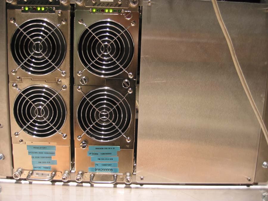
POZNPM700007168A
Sep 06, 2006FBS Wireless Base Station (NPM-2500)
Equipment Class
TNB - Licensed Non-Broadcast Station Transmitter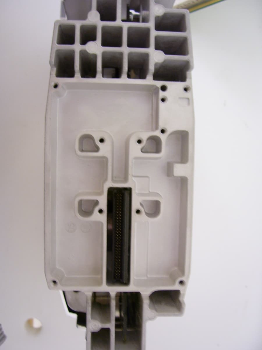
POZCPE700006553D
Aug 30, 2006CPE-300-2C0 (SOMAport Subscriber Terminal)
Equipment Class
TNB - Licensed Non-Broadcast Station Transmitter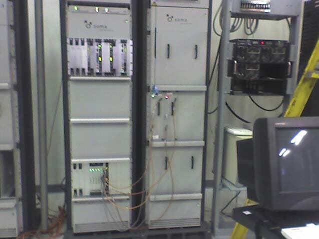
POZNPMWCS005777A
Apr 26, 2006NPM Wireless Base Station
Equipment Class
TNB - Licensed Non-Broadcast Station Transmitter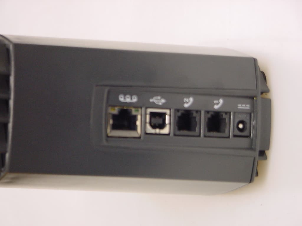
POZCPEWCS005239B
Apr 26, 2006SOMAport Subscriber wireless terminal
Equipment Class
TNB - Licensed Non-Broadcast Station Transmitter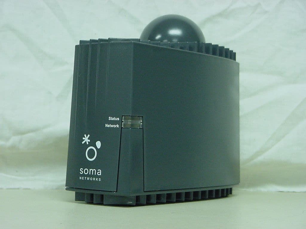
POZCPEPCS004886C
Sep 28, 2004SOMAport Subscriber Terminal
Equipment Class
PCB - PCS Licensed Transmitter