PPINPL-2HGSM PCS Cellular Telephone
Microsoft Corporation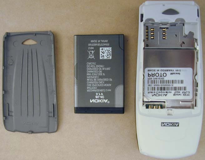
Click to zoom
Application Details
- Equipment Class
- PCE - PCS Licensed Transmitter held to ear
- Date of Grant
- Feb 20, 2003
- Application Purpose
- Original Equipment
- Date of Application
- Feb 20, 2003
- Equipment Note
- GSM PCS Cellular Telephone
- Frequency Range
- 1850.20000000 - 1909.80000000
- Company
- Microsoft Corporation
- Country
- United States
Documents & Files
Document Text
Text extracted from the exhibit documents filed with the FCC. Open a document above to read the original.
Users Manual
User’s Guide 9354993 Issue 1 DRAF T npl-2_en1_1.fm Page 1 Wednesday, August 7, 2002 10:18 AM The wireless phone described in this guide is approved for use in GSM 900, 1800 and 1900 networks. LEGAL INFORMATION Part No. 9354993 Issue No. 1 Copyright ©2003 Nokia. All rights reserved. Nokia is a registered trademark of Nokia Corporation. Nokia, Nokia Connecting People, Xpress-on, Pop-Port, the Original Accessories logos, Space Impact, Snake II, and Bumper are trademarks of Nokia Corporation and/or its affiliates. Printed in Canada 02/2003 US Patent No 5818437 and other pending patents. T9 text input software Copyright ©1999-2002. Tegic Communications, Inc. All rights reserved. Includes RSA BSAFE cryptographic or security protocol software from RSA Security. The information contained in this user guide was written for Nokia 6100 phone. Nokia operates a policy of continuous development. Nokia reserves the right to make changes and improvements to any of the products described in this document without prior notice. UNDER NO CIRCUMSTANCES SHALL NOKIA BE RESPONSIBLE FOR ANY LOSS OF DATA OR INCOME OR ANY SPECIAL, INCIDENTAL, AND CONSEQUENTIAL OR INDIRECT DAMAGES HOWSOEVER CAUSED. THE CONTENTS OF THIS DOCUMENT ARE PROVIDED “AS IS.” EXCEPT AS REQUIRED BY APPLICABLE LAW, NO WARRANTIES OF ANY KIND, EITHER EXPRESS OR IMPLIED, INCLUDING, BUT NOT LIMITED TO, THE IMPLIED WARRANTIES OF MERCHANTABILITY AND FITNESS FOR A PARTICULAR PURPOSE, ARE MADE IN RELATION TO THE ACCURACY AND RELIABILITY OR CONTENTS OF THIS DOCUMENT. NOKIA RESERVES THE RIGHT TO REVISE THIS DOCUMENT OR WITHDRAW IT AT ANY TIME WITHOUT PRIOR NOTICE. EXPORT CONTROLS This product contains commodities, technology or software exported from the United States in accordance with the Export Administration regulations. Diversion contrary to U.S. law is prohibited. FCC/INDUSTRY CANADA NOTICE Your phone may cause TV or radio interference (for example, when using a telephone in close proximity to receiving equipment). The FCC or Industry Canada can require you to stop using your telephone if such interference cannot be eliminated. If you require assistance, contact your local service facility. This device complies with part 15 of the FCC rules. Operation is subject to the condition that this device does not cause harmful interference. FCC_Layout.fm Page 91 Monday, February 10, 2003 5:16 PM Contents 3 Contents FOR YOUR SAFETY................... 5 General information 7 Stickers in the sales package ............. 7 Access codes ........................................... 7 Overview of the functions in the phone ........................................ 9 Multimedia messaging service (MMS)......................................... 9 Polyphonic sound (MIDI) ..................... 9 General Packet Radio Service (GPRS) 9 Loudspeaker .......................................... 10 MIDP JavaTM applications................ 10 Nokia OTA settings service ............... 10 Dynamic memory................................. 11 1. Your phone ......................... 12 Keys and connectors........................... 12 Standby mode....................................... 13 Screen saver....................................... 13 Wallpaper ........................................... 13 Essential indicators in standby mode ............................... 14 Putting on the wrist strap................. 15 2. Getting started................... 16 Installing the SIM card and the battery .................................... 16 Charging the battery .......................... 18 Switching the phone on and off ..... 18 Normal operating position................ 19 Keypad lock (Keyguard) ..................... 19 Changing the front cover.................. 20 3. Call functions ..................... 22 Making a call ........................................ 22 Speed dialling a phone number ... 22 Making a conference call .............. 23 Answering or rejecting an incoming call .................................. 23 Call waiting ....................................... 23 Options during a call .......................... 24 Loudspeaker ....................................... 24 4. Writing text ........................ 25 Setting predictive text input on or off ............................. 25 Using predictive text input ............... 25 Writing compound words .............. 26 Using traditional text input.............. 26 Tips for writing text ............................ 27 5. Phone book (Names) .......... 28 Selecting the phone book settings . 28 Saving names and phone numbers (Add name) .......................... 28 Saving multiple numbers and text items per name................ 29 Searching for a name in the phone book ............................... 30 Editing a name, number or text item ........................................... 30 Erasing names and numbers ............ 30 Copying phone books ......................... 30 Sending and receiving a business card..................................... 31 Speed dials ............................................ 32 Info numbers......................................... 32 Service numbers................................... 32 My numbers .......................................... 32 Caller groups......................................... 33 6. Using the menu .................. 34 Accessing a menu function .............. 34 List of menu functions ....................... 35 7. Menu functions .................. 38 Messages (Menu 1) ............................. 38 Text messages ................................... 38 Multimedia messages ..................... 43 Multimedia messages npl-2_en1_1.fm Page 3 Wednesday, August 7, 2002 1:56 PM Contents 4 memory full....................................... 46 Erasing messages............................. 47 Chat ..................................................... 47 Voice messages ................................ 48 Info messages ................................... 48 Message settings .......................…
Text truncated - open the document above for the full version.
Cover Letter(s)
American Telecommunications Certification Body Inc. 6731 Whittier Ave, McLean, VA 22101 February 17, 2003 RE: Nokia, Inc. FCC ID: PPINPL-2H After a review of the submitted information, I have a few comments on the above referenced Application. EMC Report/General: 1) Please provide photographs of both sides of the main board. Only one side appears in the internal photographs provided. Answer: Photos are uploaded to ATCB website to folder Internal Photographs. File name:Int_photog_ver2.pdf 2) Information in this application states that the device is capable of GSM 900 and GMS 1800 outside of the US. Please explain what precautions are built into the device to keep this part of the device from functioning in the U.S. Answer: This device is designed in a way that transmitter won’t get activated unless a base station is available. GSM900 and GSM1800 are not available in USA. 3) Information given in the theory of operation (pages 1 & 4) and tune up procedure (pages 5-7) state the conducted power maximum is 1 Watt, while the maximum conducted power measured was 0.818 W. Please explain. Answer: The original power level measurements were made with spectrum analyzer through power divider. We have remeasured the power levels with R&S CMU 200 GSM tester. The latter one is regarded to be more accurate. The results for the highest power level are: Ch 512 30.2 dBm Ch 661 29.9 dBm Ch 810 29.5 dBm Additionally, we have decided to change mass production target for the highest power level from 30.0 dBm to 29.7 dBm. Mass production power level tuning is carried out on mid channel. SAR Report: 4) The FCC likes to be able to confirm that the 15 cm liquid depth was present by supporting test configuration photographs or Z-axis data that is measured to 15 cm. This supplemental information was not provided for the actual test. Please confirm that the liquid depth was at least 15 cm, and if available please provide the photograph. Answer: The shape of the Z-axis plots show, that there were no harmful reflections from upper surface of the liquid in the depth where the actual cube scanning took place. We confirm that the liquid depth was 15 +/- 0.5 cm during all measurements as stated in the SAR report. 5) The FCC prefers for all plots to be provided. Please provide a justification for not providing allplots. Note that if the channels tested for each configuration (left, right, cheek, tilt/ear, extended,retracted etc.) have similar SAR distributions, a plot of the highest SAR for each test configuration should be sufficient as long as this is stated; otherwise additional plots should be included to document the different SAR distributions in order to identify peak locations relative to device and phantom. Answer: The SAR distribution plots are substantially similar or equivalent to the plots submitted regardless of used channel in each mode and position. 6) During z-axis plots, the first 2 points should be made in the first 10 mm. This does not appear to have been the case for one of the z-axis plots. Answer: The problem is related only to the visualization software. The SAR scans have been performed correctly. Please see quotation from SPEAG correspondence: We have carefully analyzed your problem. As predicted, it is just a problem of visualization. All data are assessed correctly. The surface is not at point 0 but at the location of the first triangle in the plot. This is a result of the measurement strategy implemented in DASY3 which has been completely revised in DASY4, i.e., DASY4 always evaluates the correct z- scan. Unfortunately, we are not able to fix this problem in DASY3 at this time. In summary: - The spatial peak SAR averaged over 1g and 10g are correctly evaluated - The z-scan is correctly displayed. The location of the surface is at the first shown triangular point, i.e., the first extrapolated point is on the surface. Please be aware that the z-scan is normal to the coordinate system of the probe and not necessarily to the surface of the phantom. 7) Please provide a description of the averaging (integration) procedures to get 1-g SAR from final interpolated grid. Answer: The measured volume of 32x32x35mm (cube 5x5x7) contains about 35g of tissue. The first procedure is an extrapolation (incl. boundary correction) to get the points between the lowest measured plane and the surface. The next step uses 3D interpolation to get all points within the measured volume in a 1mm grid (3500 points). In the last step, a 1g cube is placed numerically into the volume and its averaged SAR is calculated. This cube is then moved around until the highest averaged SAR is found. 8) The FCC asks that the SAR laboratory re-measure the peak power to ensure that the device is fully functioning during the SAR test at maximum TX power. Reported power results appear to be identical to EMC EIRP reported values. Were conducted measurements made during SAR testing? . What assurance can be provided that the device was functioning correctly at full maximum power during the SAR test. Answer: Power levels were not measured during or after SAR measurements and so such data is not available. The phone was packed carefully for transportation between the labs. If the package had shown signs of rough handling, the sample had not been used for SAR measurements. Power level setting is stored in digital format in memory and power level setting does not change due to environmental conditions. The phones have been designed to stand transportation e.g. from factory to consumer. Call was established by communication tester and highest power level was chosen for EMC and SAR measurements. The battery was fully charged for each scan. It is evident, that power levels have been the same in EIRP and SAR measurements except for the minor power drift typical for the tested handset model. Timothy R. Johnson Examining Engineer mailto: [email protected] The items indicated above must be submitted before processing can continue on the above referenc…
Text truncated - open the document above for the full version.
Cover Letter(s)
American Telecommunications Certification Body Inc. 6731 Whittier Ave, McLean, VA 22101 February 17, 2003 RE: Nokia, Inc. FCC ID: PPINPL-2H After a review of the submitted information, I have a few comments on the above referenced Application. EMC Report/General: 1) Please provide photographs of both sides of the main board. Only one side appears in the internal photographs provided. 2) Information in this application states that the device is capable of GSM 900 and GMS 1800 outside of the US. Please explain what precautions are built into the device to keep this part of the device from functioning in the U.S. 3) Information given in the theory of operation (pages 1 & 4) and tune up procedure (pages 5-7) state the conducted power maximum is 1 Watt, while the maximum conducted power measured was 0.818 W. Please explain. SAR Report: 4) The FCC likes to be able to confirm that the 15 cm liquid depth was present by supporting test configuration photographs or Z-axis data that is measured to 15 cm. This supplemental information was not provided for the actual test. Please confirm that the liquid depth was at least 15 cm, and if available please provide the photograph. 5) The FCC prefers for all plots to be provided. Please provide a justification for not providing all plots. Note that if the channels tested for each configuration (left, right, cheek, tilt/ear, extended, retracted etc.) have similar SAR distributions, a plot of the highest SAR for each test configuration should be sufficient as long as this is stated; otherwise additional plots should be included to document the different SAR distributions in order to identify peak locations relative to device and phantom. 6) During z-axis plots, the first 2 points should be made in the first 10 mm. This does not appear to have been the case for one of the z-axis plots. 7) Please provide a description of the averaging (integration) procedures to get 1-g SAR from final interpolated grid. 8) The FCC asks that the SAR laboratory re-measure the peak power to ensure that the device is fully functioning during the SAR test at maximum TX power. Reported power results appear to be identical to EMC EIRP reported values. Were conducted measurements made during SAR testing? . What assurance can be provided that the device was functioning correctly at full maximum power during the SAR test. Timothy R. Johnson Examining Engineer mailto: [email protected] The items indicated above must be submitted before processing can continue on the above referenced application. Failure to provide the requested information may result in application termination. Correspondence should be considered part of the permanent submission and may be viewed from the Internet after a Grant of Equipment Authorization is issued. z Page 2February 17, 2003 Please do not respond to this correspondence using the email reply button. In order for your response to be processed expeditiously, you must submit your documents through the AmericanTCB.com website. Also, please note that partial responses increase processing time and should not be submitted. Any questions about the content of this correspondence should be directed to the sender.
External Photos
FCCID: PPINPL-2H External Photographs
Internal Photos
FCCID: PPINPL-2H Picture 1 Picture 2 FCCID: PPINPL-2H Picture 3 Picture 4 FCCID: PPINPL-2H Picture 5
Internal Photos
FCCID: PPINPL-2H Picture 6 FCCID: PPINPL-2H Picture 7 FCCID: PPINPL-2H Picture 8
RF Exposure Info
SAR Test Report Template / Version 1.0 T:\Projects\npl-2\results\emc\SAR\SAR0305_04.doc Copyright 2003 TCC Salo Copyright TCC Salo P.O. Box 86 Joensuunkatu 7E / Kiila 1B FIN-24101 SALO, FINLAND Tel. +358 (0) 7180 08000 Fax. +358 (0) 7180 45220 2 (54) CONTENTS CONTENTSCONTENTS CONTENTS 1. SUMMARY FOR SAR TEST REPORT............................................................................................................................. 4 1.1 MAXIMUM RESULTS FOUND DURING SAR EVALUATION............................................................................................................ 4 1.1.1 Head Configuration....................................................................................................................................................... 4 1.1.2 Body Worn Configuration........................................................................................................................................... 4 1.1.3 Body Worn Configuration, SAR values doubled, corresponding to GPRS mode................................. 5 1.1.4 Measurement Uncertainty......................................................................................................................................... 5 1.2 EIRP MEASUREMENTS................................................................................................................................................................ 5 2. DESCRIPTION OF THE TESTED DEVICE(S)................................................................................................................ 6 2.1 DEVICE DESCRIPTION................................................................................................................................................................... 6 2.2 PICTURE OF PHONE..................................................................................................................................................................... 6 2.3 DESCRIPTION OF THE ANTENNA .................................................................................................................................................. 6 2.4 BATTERY OPTIONS...................................................................................................................................................................... 7 2.5 ACCESSORIES................................................................................................................................................................................ 7 2.6 BODY WORN ACCESSORIES......................................................................................................................................................... 7 3. DESCRIPTION OF THE TEST EQUIPMENT................................................................................................................. 8 3.1 A UTOMATED NEAR - FIELD SCANNING SYSTEM .............................................................................................................................. 8 3.2 ROBOT......................................................................................................................................................................................... 8 3.3 ISOTROPIC E-FIELD PROBE ET3DV6R........................................................................................................................................ 9 3.4 DEVICE HOLDER ............................................................................................................................................................................ 9 3.5 DIPOLE ANTENNAS FOR VALIDATION..........................................................................................................................................10 3.6 PHANTOM..................................................................................................................................................................................10 3.7 BASE STATION SIMULALTOR......................................................................................................................................................11 3.8 ADDITIONAL EQUIPMENT NEEDED IN SYSTEM CHECK.................................................................................................................11 3.9 RF CHARACTERISTICS OF THE TEST SITE ....................................................................................................................................11 4. TEST CONDITIONS.........................................................................................................................................................12 4.1 AMBIENT CONDITIONS..............................................................................................................................................................12 4.2 SYSTEM PERFORMANCE CHECK..................................................................................................................................................12 4.3 TISSUE SIMULANTS....................................................................................................................................................................13 4.3.1 Measured values of liqid parameters ..................................................................................................................13 4.3.2 Recipes of tissue simulating liquids....................................................................................................................13 5. DEVICE POSITIONING...................................................................................................................................................14 5.1 POSITIONING PROCEDURES.......................................................................................................................................................14 5.1.1 Cheek/Touch Position...................................................................................................................…
Text truncated - open the document above for the full version.
Test Report
DOCUMENT NAME: NPL2_504.DOC 1 (22) The test results are valid for the tested unit(s) only. This report shall not be reproduced except in full, without the written permission of the testing laboratory. TCC Tampere Box 68 FIN-33721 TAMPERE FINLAND Tel. +358 7180 46800 Fax. +358 7180 46880 TCC Tampere Test report for NPL-2 DOCUMENT NAME: NPL2_504.DOC 2 (22) The test results are valid for the tested unit(s) only. This report shall not be reproduced except in full, without the written permission of the testing laboratory. TCC Tampere Box 68 FIN-33721 TAMPERE FINLAND Tel. +358 7180 46800 Fax. +358 7180 46880 TCC Tampere CONTENTS 1 LABORATORY INFORMATION ................................................................................................................3 2 CUSTOMER INFORMATION ....................................................................................................................3 3 SUMMARY OF TEST RESULTS...............................................................................................................4 4 EUT INFORMATION..................................................................................................................................5 4.1 EUT description ..................................................................................................................................5 4.2 EUT certification codes.......................................................................................................................5 5 EUT TEST SETUPS ..................................................................................................................................5 6 APPLICABLE STANDARDS......................................................................................................................5 7 CONDUCTED RF OUTPUT POWER .......................................................................................................6 7.1 Test setup ...........................................................................................................................................6 7.2 EUT operation mode...........................................................................................................................6 7.3 Results ................................................................................................................................................6 7.4 Screen shots .......................................................................................................................................7 8 RADIATED RF OUTPUT POWER ............................................................................................................9 8.1 Test setup ...........................................................................................................................................9 8.2 Test method ........................................................................................................................................9 8.3 EUT operation mode.........................................................................................................................10 8.4 Limit ..................................................................................................................................................10 8.5 Results ..............................................................................................................................................10 9 99% OCCUPIED BANDWIDTH...............................................................................................................11 9.1 Test setup .........................................................................................................................................11 9.2 EUT operation mode.........................................................................................................................11 9.3 Results ..............................................................................................................................................11 9.4 Screen shots .....................................................................................................................................12 10 BAND-EDGE COMPLIANCE...................................................................................................................14 10.1 Test setup .........................................................................................................................................14 10.2 EUT operation mode.........................................................................................................................14 10.3 Limit ..................................................................................................................................................14 10.4 Results ..............................................................................................................................................14 10.5 Screen shots .....................................................................................................................................15 11 SPURIOUS EMISSIONS AT ANTENNA TERMINALS ...........................................................................16 11.1 Test setup .........................................................................................................................................16 11.2 Test method ......................................................................................................................................16 11.3 EUT operation mode.........................................................................................................................16 11.4 Limit ..................................................................................................................................................16 11.5 Results .........................................................................................................................................…
Text truncated - open the document above for the full version.
Test Setup Photos
FCC ID: PPINPL-21 (2) TCC Tampere P.O. Box 68 FIN -33721 Tampere FINLAND Tel. +358 7180 46800 Fax. +358 7180 46880 TCC Tampere EUT test setup FCC ID: PPINPL-22 (2) TCC Tampere P.O. Box 68 FIN -33721 Tampere FINLAND Tel. +358 7180 46800 Fax. +358 7180 46880 TCC Tampere
Contact Information
Applicant
Hasnain Syed(Director, EMC, SI, and RF Compliance)
Technical Contact
Non-Technical Contact
Nokia GmbHTomi Vahatiitto
[email protected]+49 173 2830 836
Test Firm
TCC TampereJari Jantunen
Technical Specifications
| # | Rule Parts | Frequency Range | Power Output | Emission | Tolerance |
|---|---|---|---|---|---|
| 1 | 24E | 1.85 GHz - 1.91 GHz | 840.00 mW | 300KGXW | 0.1000000000 ppm |
Other Applications from Microsoft Corporation

PPIRM-884
Jul 24, 2012GSM/WCDMA cellular phone w/BT and WLAN
Equipment Class
PCE - PCS Licensed Transmitter held to ear
PPIRM-714
Mar 31, 2012GSM/WCDMA Cellular phone w/BT and WLAN
Equipment Class
DTS - Digital Transmission System
PPIRM-813
Nov 20, 2011GSM/WCDMA cellular phone w/BT and WLAN
Equipment Class
DSS - Part 15 Spread Spectrum Transmitter
PPIRM-800
Nov 15, 2011GSM cellular phone w/BT
Equipment Class
PCE - PCS Licensed Transmitter held to ear
PPIRM-781
Oct 10, 2011GSM/WCDMA cellular phone w/BT
Equipment Class
DSS - Part 15 Spread Spectrum Transmitter