PPIRM-77XHGSM 850/1800/1900 Cellular Telephone
Microsoft Corporation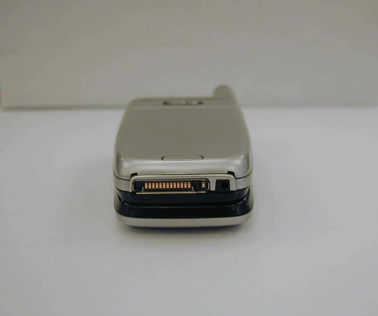
Click to zoom
Application Details
- Equipment Class
- PCE - PCS Licensed Transmitter held to ear
- Date of Grant
- Sep 08, 2005
- Application Purpose
- Original Equipment
- Date of Application
- Jul 28, 2005
- Equipment Note
- GSM 850/1800/1900 Cellular Telephone
- Frequency Range
- 824.20000000 - 848.80000000
- Company
- Microsoft Corporation
- Country
- United States
Documents & Files
Document Text
Text extracted from the exhibit documents filed with the FCC. Open a document above to read the original.
Users Manual
Nokia 6101 and Nokia 6102 User Guide1Copyright © 2005 Nokia Nokia 6101 and Nokia 6102 User Guide 9240568 Issue 1 Issue 1te 6101_6102.ENv1_9240568_UG.fm Page 1 Tuesday, June 7, 2005 2:59 PM 2Copyright © 2005 Nokia DECLARATION OF CONFORMITY We, NOKIA CORPORATION declare under our sole responsibility that the products RM-76 and RM-77 are in conformity with the provisions of the following Council Directive:1999/5/EC. A copy of the Declaration of Conformity can be found at http://www.nokia.com/phones/declaration of conformity/ . LEGAL INFORMATION Part No. 9240568, Issue No. 1 Copyright © 2005 Nokia. All rights reserved. Reproduction, transfer, distribution or storage of part or all of the contents in this document in any form without the prior written permission of Nokia is prohibited. Nokia, Nokia Connecting People, Xpress-on, the Nokia Original Enhancements logo, and Pop-Port are trademarks or registered trademarks of Nokia Corporation. Other product and company names mentioned herein may be trademarks or tradenames of their respective owners. Nokia tune is a sound mark of Nokia Corporation. US Patent No 5818437 and other pending patents. T9 text input software Copyright (C) 1997-2005. Tegic Communications, Inc. All rights reserved. Includes RSA BSAFE cryptographic or security protocol software from RSA Security. Java is a trademark of Sun Microsystems, Inc. The information contained in this user guide was written for the Nokia 6101 and Nokia 6102 products. Nokia operates a policy of ongoing development. Nokia reserves the right to make changes to any of the products described in this document without prior notice. UNDER NO CIRCUMSTANCES SHALL NOKIA BE RESPONSIBLE FOR ANY LOSS OF DATA OR INCOME OR ANY SPECIAL, INCIDENTAL, AND CONSEQUENTIAL OR INDIRECT DAMAGES HOWSOEVER CAUSED. THE CONTENTS OF THIS DOCUMENT ARE PROVIDED "AS IS." EXCEPT AS REQUIRED BY APPLICABLE LAW, NO WARRANTIES OF ANY KIND, EITHER EXPRESS OR IMPLIED, INCLUDING, BUT NOT LIMITED TO, THE IMPLIED WARRANTIES OF MERCHANTABILITY AND FITNESS FOR A PARTICULAR PURPOSE, ARE MADE IN RELATION TO THE ACCURACY AND RELIABILITY OR CONTENTS OF THIS DOCUMENT. NOKIA RESERVES THE RIGHT TO REVISE THIS DOCUMENT OR WITHDRAW IT AT ANY TIME WITHOUT PRIOR NOTICE. 6101_6102.ENv1_9240568_UG.fm Page 2 Wednesday, June 8, 2005 1:36 PM Nokia 6101 and Nokia 6102 User Guide3Copyright © 2005 Nokia EXPORT CONTROLS This device may contain commodities, technology, or software subject to export laws and regulations from the U.S. and other countries. Diversion contrary to law is prohibited. FCC/INDUSTRY CANADA NOTICE Your device may cause TV or radio interference (for example, when using a telephone in close proximity to receiving equipment). The FCC or Industry Canada can require you to stop using your telephone if such interference cannot be eliminated. If you require assistance, contact your local service facility. This device complies with part 15 of the FCC rules. Operation is subject to the condition that this device does not cause harmful interference. 6101_6102.ENv1_9240568_UG.fm Page 3 Tuesday, June 7, 2005 2:59 PM Contents 4Copyright © 2005 Nokia Contents For your safety...................................................................................... 8 General information ........................................................................... 11 Overview of functions........................................................................................................ 11 Access codes......................................................................................................................... 11 Configuration settings service ........................................................................................ 12 Download content and applications ............................................................................. 12 Nokia support on the Web ............................................................................................... 12 1. Get started.................................................................................... 13 Open the fold............................................................................................................... 13 Install the SIM card and the battery .................................................................... 13 Charge the battery..................................................................................................... 14 Switch the phone on and off .................................................................................. 14 Normal operating position ...................................................................................... 15 2. Your phone ................................................................................... 16 Keys and parts............................................................................................................. 16 Standby mode ............................................................................................................. 17 Keypad lock (keyguard)............................................................................................. 19 3. Call functions ............................................................................... 20 Make a call................................................................................................................... 20 Answer or reject a call .............................................................................................. 20 Options during a call................................................................................................. 21 4. Write text ..................................................................................... 22 Settings ......................................................................................................................... 22 Predictive text input.................................................................................................. 22 Traditional text input…
Text truncated - open the document above for the full version.
Users Manual
Draf t Nokia 6102h User Guide addendum ■Hearing Aid Compatibility Your mobile device model complies with FCC rules governing hearing aid compatibility with hearing aids operating in microphone mode. These rules require phone models to fulfil the telephone near field category M3 or higher category. The M-value, shown on the device box, refers to lower radio frequency (RF) emissions. A higher M-value generally indicates that a device model has a lower RF emissions level, which may improve the likelihood that the device will operate with certain hearing aids. Some hearing aids are more immune than others are to interference. Please consult your hearing health professional to determine the M rating of your hearing aid and whether your hearing aid will work with this device. GSM networks in the United States utilize 850 and 1900 MHz bands. Your phone operates on both bands, and is enhanced with a "hearing aid mode" to activate if needed. In this mode, the phone reduces the maximum power that it can use when operating in the GSM 850 MHz band, thus potentially reducing interference with a hearing aid. When your phone is operating in the GSM 1900 MHz band, using the hearing aid mode does not impact the phone's operations. There is also no benefit to using the hearing aid mode if you do not wear hearing aids. The type of hearing aid and how far the phone is from a network base station both contribute to whether the hearing aid mode is beneficial. Hearing aid users should experiment with use of the hearing aid mode to determine whether it affects the operation of their hearing aids while using the mobile phone. Activate the hearing aid mode Select Menu> Settings> Enhancement settings> Hearing aid> On. An "ear" icon is displayed on the start screen. If you make an emergency call to 911 while the phone is in the hearing aid mode, the phone will use as much power as it needs (up to the maximum available) to connect the call. More information on accessibility can be found at www.nokiaaccessibility.com ■Certification information (SAR) The following text supplements the section entitled "Certification Information" in the User Guide: THIS MOBILE DEVICE MEETS GUIDELINES FOR EXPOSURE TO RADIO WAVES. Your mobile device is a radio transmitter and receiver. It is designed not to exceed the limits for exposure to radio waves recommended by international guidelines. These guidelines were Draf t developed by the independent scientific organization ICNIRP and include safety margins designed to assure the protection of all persons, regardless of age and health. The exposure guidelines for mobile devices employ a unit of measurement known as the Specific Absorption Rate or SAR. The SAR limit stated in the ICNIRP guidelines is 2.0 watts/ kilogram (W/kg) averaged over ten grams of tissue. Tests for SAR are conducted using standard operating positions with the device transmitting at its highest certified power level in all tested frequency bands. The actual SAR level of an operating device can be below the maximum value because the device is designed to use only the power required to reach the network. That amount changes depending on a number of factors such as how close you are to a network base station. The highest SAR value under the ICNIRP guidelines for use of the device at the ear is 0.68 W/kg. Use of device accessories and enhancements may result in different SAR values. SAR values may vary depending on national reporting and testing requirements and the network band. Additional SAR information may be provided under product information at www.nokia.com. Your mobile device is also designed to meet the requirements for exposure to radio waves established by the Federal Communications Commission (USA) and Industry Canada. These requirements set a SAR limit of 1.6 W/kg averaged over one gram of tissue. The highest SAR value for reported for the Nokia 6102h phone under this standard during product certification for use at the ear is 0.48 W/kg and when properly worn on the body is 1.07 W/kg. Information can be found at http://www.fcc.gov/oet/fccid by searching the equipment authorization system using FCCID PPIRM-77XH. Nokia Inc. 7725 Woodland Center Blvd., Ste. 150 Tampa, FL 33614 Telephone: 1-888-NOKIA-2U (1-888-665-4228) Facsimile: 1-813-249-9619 TTY/TDD Users: 1-800-24-NOKIA (1-800-246-6542) www.nokia.com/us www.nokiahowto.com Copyright © 2005 Nokia. All rights reserved. Version 1 xxxxxxx
Cover Letter(s)
NCKIA NOKIA MOBILE PHONES Lise-Meitner-Strasse 11 D-89081 Ulm, Germany +49(0)731-1754-0 +49(0)731-1754-6800 19-July-200S Federal Communications Commission Authorization Et Evaluation Division, 7435 Oakland Mills Road, Columbia, MD. 21046 Attention: Equipment Authorization Branch REOUEST FOR CONFIDENTIALllY and HAC GRANT NOTE Pursuant to Sections 0.457 (d)(1)(ii) and 0.459 of the Commission's Rules, the Applicant hereby requests confidential treatment of same of the information accompanying this Application of FCC ID: PPIRM-77XH and as outlined below: -Exhibit 4: RF Block Diagram -Exhibit 5: Schematic Diagrams -Exhibit 10: List ofActive Devices, Tune-Up Procedure and Part list Exhibit 12: Theory of Operation, Frequency determining part24, frequency range and Harmonics part 24 These materials contain trade secrets and proprietary information not customarily released to the public and the public disclosure of these matters might be harmful 10 the Applicant and provide unjustified benefits to its competitors. The Applicant understands that pursuant to Rule 0.457 (d)(1)(ii) disclosure of this Application and all accompanying documentation will not be made before the date of the Grant für thisApplication. Together with this filing we request the grant note regarding Hearing Aid Compatibility (HAC) capability. NOKIA MOBILE PHONES Br~'ng Program Manager, Ulm
Cover Letter(s)
1 (4) Sept. 9 th , 2005 PPIRM-77XH Answers Re: FCC ID PPIRM-77XH To: Martin Perrine [email protected] FCC Application Processing Branch Applicant: Nokia GmbH Correspondence Reference Number: 29544 SAR 1) Please justify that multi-peak SAR procedures were followed. See page 26. Remeasure as necessary. • The principle of carrying out cube scans with the peaks inside 2 dB from the highest peak is valid with the measurements in this SAR report. None of the measurements required scan of second cube based on the 2 dB rule. 2) Please explain the statement "EGPRS mode was not measured, because maximum averaged output power is more than 3 dB lower in EGPRS mode than in GPRS mode." on page 4. EGPRS results were later provided also the power statement does not appear to be correct. Please also confirm that the GPRS mode does not have voice capability. The EMC radiated power report suggests that GPRS works with the flip open. • The SAR reports of PPIRM-77H and PPIRM-77XH may be confusing as the both have only the type RM-77 in footer and full FCC ID is given only on cover page. The statement "EGPRS mode was not measured, because maximum averaged output power is more than 3 dB lower in EGPRS mode than in GPRS mode." is valid for PPIRM-77XH. PPIRM-77XH does not have voice capability in EGPRS or GPRS mode. EMC 1) For the radiated power test -Please provide details of the receiver including measurement settings and BW. -Please explain the differences in power noted for GPRS and EGPRS noted on pages 6 and 7 of 9. -Please explain the differences in the form 731 line items. • RMS Average peak, 1 MHz Band Width • GPRS lists values in dual slot GMSK mode, EGPRS shows results of single slot EDGE • Difference is due to GMSK and Edge modulation supported by the phone 2) Form 731 shows emission designator G7W has been associated with EDGE PSK modualtion. Does this phone have EDGE capability? If so please provide test results. • Phone is supporting EDGE, EDGE results can be found in Part 22 and part 24 EMC report. 2 (4) Sept. 9 th , 2005 PPIRM-77XH Answers HAC 1) Please provide validation test information for AM and WD signal types as recommended by C63.19. • Information for AM not available, response to AM modulated signal is not relevant to the test results. GSM-signal is simulated with pulse modulation in the both frequency bands, 850MHz and 1900MHz, and modulation response is examined. 2) Please state the FCC ID in the test report. • FCC ID is mentioned on the front page of the HAC report. 3) Please provide full details of the device measured power at the time of testing. Please detail how HAC mode power compares to full power. • Calibration data can be found in the Exhibit 10 “Tune up procedure”. Radiated powers were measured from the SAR samples. 4) Please provide an uncertainty budget and separately discuss locally determined components. • Document uploaded beside this correspondence. See file: HAC_ProbeCalibrationUncertainty.doc 5) Please provide full calibration documents for the system including verification hardware and target value justification. • Documents uploaded beside this correspondence. See files: 1) Probe H3DV6_2005 01 20.pdf 2) Dipole CD835V3_SN 1004_2005 02 23.pdf 3) Dipole CD1880V3_SN 1003_2005 02 23.pdf 4) Probe ER3DV6_2005 01 31.pdf 6) Please confirm the E field results given on page 8. There appears to be a discrepancy with data on page 15. • The reference result in the Table on page 8 is averaged maximum of high end and of low end of the dipole arms: 133.9 V/m. Corresponding value from the validation measurement is (141.8+136.3)/2 = 139.1. • The other E-field measurement result given in the same table (163.8) should be correspondingly: (162.8+163.8)/2 = 163.3. 7) Please provide full setup details for the validation measurement. 3 (4) Sept. 9 th , 2005 PPIRM-77XH Answers • The input signal was an unmodulated continuous wave, and average input power = 100mW after adjustment for return loss. The proper measurement of the 1cm probe to dipole separation, which is measured from the top surface of the dipole to the calibration reference point of the sensor, defined by the probe manufacturer. A dipole antenna meeting the requirements in PC63.19 was placed in the position normally occupied by the WD. The length of the dipole was scanned with both E-field and H- field probes and the maximum values for each were recorded. Setup for desired output power to dipole: dipole Power meter for input power Power meter for return loss 8) Please provide full details of the scan setup including resolutions, and dwell and integration times. • Measurement step size is 5mm, measurement time 0.5s, zeroing time 0.5s and zeroing period 10s. Measuring time is long compared to burst repetition period. 9) Please provide results after probe rotation in the worst case configuration. • This is not done. Standard requires this for 1-D probes, and we have 3- D probes. 10) Please reestablish peak field values using C63.19 PMF procedures given in Annex C.3.1. • See question/answer 1): Theoretical Crest Factor 8.3 was used. 11) Please clarify information on the contour plots. Page 18 seems to report a value after exclusion while page 19 seems to report a value prior to the exclusion. • The plots are documenting measuring setup and results for each subgrid. The results after exclusion are tabulated in Section 5. 12) Please detail drift measurement procedures. • Power reference measurement, which is the field measurement at a specified reference position, is done just before the actual measurement(e.g. HAC E-field measurement). Just after the actual measurement the field is remeasured at the same location as the most recent Power reference was measured. The field difference between the two reference measurements in dB is giving drift. This is monitoring power drift of the device under test. 4 (4) Sept. 9 th , 2005 PPIRM-77XH Answers 13) Please provide data demonstrating that measurement to probe center is conservative if …
Text truncated - open the document above for the full version.
External Photos
1 (4) NOKIA Mobile Phones R&D Ulm 8 July 2005 External Photos of FCC ID : PPIRM-77XH Front view, flap closed 2 (4) NOKIA Mobile Phones R&D Ulm 8 July 2005 Front view, flap closed 3 (4) NOKIA Mobile Phones R&D Ulm 8 July 2005 Rear view. 4 (4) NOKIA Mobile Phones R&D Ulm 8 July 2005 Bottom view.
ID Label/Location Info
1 (1) NOKIA Mobile Phones R&D ULM 21.7.2005 POSITION OF AREAS FOR LABEL STICKERS FOR NOKIA PPIRM-77XH Type label as below will be placed hereType label as below will be placed here FCC ID: PPIRM-77XH
Internal Photos
1 (6) NOKIA Mobile Phones R&D Ulm 12.7.2005 Internal Photos of FCC ID: PPIRM-77XH Rear view, back cover removed. 2 (6) NOKIA Mobile Phones R&D Ulm 12.7.2005 Phone disassembled, front view 3 (6) NOKIA Mobile Phones R&D Ulm 12.7.2005 Phone disassembled, rear view 4 (6) NOKIA Mobile Phones R&D Ulm 12.7.2005 Engine Module Board, Flap Module Board, Antenna (Shielding assembled) 5 (6) NOKIA Mobile Phones R&D Ulm 12.7.2005 Engine Module Board (Shieldings disassembled) 6 (6) NOKIA Mobile Phones R&D Ulm 12.7.2005 Flap Module (Shieldings disassembled) Mini Display side (outer) Main Display side (inner)
RF Exposure Info
Nokia ____________________________________________________________________________ SAR Report Salo_SAR_0528_01 Applicant: Nokia Corporation Type: RM-77 Copyright © 2005 TCC Nokia 2/38 CONTENTS 1. SUMMARY OF SAR TEST REPORT............................................................................................................................................. 3 1.1 TEST DETAILS.............................................................................................................................................................................3 1.2 MAXIMUM RESULTS....................................................................................................................................................................3 1.2.1 Head Configuration........................................................................................................................................................ 3 1.2.2 Body Worn Configuration............................................................................................................................................ 3 1.2.3 Maximum Drift................................................................................................................................................................ 3 1.2.4 Measurement Uncertainty........................................................................................................................................... 4 2. DESCRIPTION OF THE DEVICE UNDER TEST........................................................................................................................... 4 2.1 PICTURE OF THE DEVICE..............................................................................................................................................................4 2.2 DESCRIPTION OF THE ANTENNA..................................................................................................................................................5 3. TEST CONDITIONS..................................................................................................................................................................... 5 3.1 TEMPERATURE AND HUMIDITY....................................................................................................................................................5 3.2 TEST SIGNAL, FREQUENCIES AND OUTPUT POWER......................................................................................................................5 4. DESCRIPTION OF THE TEST EQUIPMENT...............................................................................................................................5 4.1 MEASUREMENT SYSTEM AND COMPONENTS................................................................................................................................5 4.1.1 Isotropic E-field Probe 1396........................................................................................................................................ 7 4.2 PHANTOMS................................................................................................................................................................................7 4.3 TISSUE SIMULANTS....................................................................................................................................................................7 4.3.1 Tissue Simulant Recipes............................................................................................................................................... 8 4.3.2 System Checking............................................................................................................................................................. 8 4.3.3 Tissue Simulants used in the Measurements.......................................................................................................... 9 5. DESCRIPTION OF THE TEST PROCEDURE............................................................................................................................. 10 5.1 DEVICE HOLDER....................................................................................................................................................................... 10 5.2 TEST POSITIONS...................................................................................................................................................................... 11 5.2.1 Against Phantom Head.............................................................................................................................................. 11 5.2.2 Body Worn Configuration......................................................................................................................................... 11 5.3 SCAN PROCEDURES.................................................................................................................................................................. 12 5.4 SAR AVERAGING METHODS..................................................................................................................................................... 12 6. MEASUREMENT UNCERTAINTY.............................................................................................................................................. 13 7. RESULTS.................................................................................................................................................................................... 14 APPENDIX A: SYSTEM CHECKING SCANS........................................................................................................................................ 16 APPENDIX B: MEASUREMENT SCANS.............................................................................................................................................. 20 APPENDIX C: RELEVANT PAGES FROM PROBE CALIBRATION REPORT(S)................................................................................ 37 A…
Text truncated - open the document above for the full version.
Test Report
FCC Part 15B Compliance Test Report / Template Version 2.0 T:\Projects\RM-77\results\emc\FCC\Tre_FCC_0528_03.doc Copyright © TCC Nokia 1 (10) TCC Nokia Tampere Laboratory P.O. Box 68 Sinitaival 5 FIN-33720 TAMPERE, FINLAND Tel. +358 (0) 7180 46800 Fax. +358 (0) 7180 46880 FCC Part 15B Compliance Test Report Test Report no.: Tre_FCC_0528_03.doc Date of Report: 15.7.2005 Number of pages: 10 Customer’s Contact person: Thomas Reitmayer Testing laboratory: TCC Nokia Tampere Laboratory P.O. Box 68 Sinitaival 5 FIN-33720 TAMPERE, FINLAND Tel. +358 (0) 7180 46800 Fax. +358 (0) 7180 46880 FCC listing no.: IC recognition no.: 94436 3608 Client: Nokia Corporation Lise Meitner Strasse 10 89081 ULM GERMANY Tel. +49 731 1754 0 Fax. +49 731 1754 6800 Tested devices/ accessories: GSM phone RM-77 / Battery BL-4C, Headset HS-23, AC charger AC-3 FCC ID: PPIRM-77XH IC: 661U-RM77 Supplement reports: - Testing has been carried out in accordance with: CFR 47, FCC rules Part 15 Subpart B, ANSI C63.4 (2003), ICES-003, CISPR 22 and IC standards RSS-132, RSS-133 and RSS-210. Deviations, modifications or clarifications (if any) to above mentioned documents are written in each section under "Test method and limit". Documentation: The test report must always be reproduced in full; reproduction of an excerpt only is subject to written approval of the testing laboratory. The documentation of the testing performed on the tested devices is archived for 15 years at TCC Nokia. Test Results: The EUT complies with the requirements in respect of all parameters subject to the test. The test results relate only to devices specified in this document. Date and signature for the contents: Jari Jantunen, System Manager FCC Part 15B Compliance Test Report / Template Version 2.0 T:\Projects\RM-77\results\emc\FCC\Tre_FCC_0528_03.doc Copyright © TCC Nokia 2 (10) TCC Nokia Tampere Laboratory P.O. Box 68 Sinitaival 5 FIN-33720 TAMPERE, FINLAND Tel. +358 (0) 7180 46800 Fax. +358 (0) 7180 46880 1. Summary for FCC Part 15B Compliance Test Report Date of receipt 12.7.2005 Testing completed 13.7.2005 The customer's contact person Thomas Reitmayer Test Plan referred to \EMC\TESTPLAN\ Notes - Document name T:\Projects\RM-77\results\emc\FCC\Tre_FCC_0528_03.doc 1.1. EUT and Accessory Information The EUT is a triple band (GSM850/1800/1900) mobile phone with GPRS and EGPRS. GSM bands are tested in idle mode. Product Type SN HW MV SW DUT GSM phone RM-77 356643000001955 5040 - 3.37 40301 Battery BL-4C M136D20691577 - - - 40303 Headset HS-23 - 0.6 0.4 0.2 40224 AC Charger AC-3 - 1.1 0.3 - 40239 1.2. Summary of Test Results GSM 850: Section in CFR 47 Section in ICES-003 (RSS-132) Name of the test Result 15.107, a 5.3 AC powerline conducted emissions PASSED 15.109, a 5.5 (6.6) Radiated emissions PASSED GSM 1900: Section in CFR 47 Section in ICES-003 (RSS-133) Name of the test Result 15.107, a 5.3 AC powerline conducted emissions NP 15.109, a 5.5 (9) Radiated emissions PASSED PASSED The EUT complies with the essential requirements in the standard. FAILED The EUT does not comply with the essential requirements in the standard. NP The test was not performed by the TCC Nokia Tampere Laboratory. FCC Part 15B Compliance Test Report / Template Version 2.0 T:\Projects\RM-77\results\emc\FCC\Tre_FCC_0528_03.doc Copyright © TCC Nokia 3 (10) TCC Nokia Tampere Laboratory P.O. Box 68 Sinitaival 5 FIN-33720 TAMPERE, FINLAND Tel. +358 (0) 7180 46800 Fax. +358 (0) 7180 46880 CONTENTS 1. Summary for FCC Part 15B Compliance Test Report.............................................. 2 1.1. EUT and Accessory Information ............................................................................................2 1.2. Summary of Test Results .......................................................................................................2 2. AC powerline conducted emissions (FCC §15.107, ICES-003 section 5.3)...................... 4 2.1. Test setup ..............................................................................................................................4 2.2. Test method and limit .............................................................................................................4 2.3. GSM 850 Test results ............................................................................................................5 3. Radiated emissions (FCC §15.109, ICES-003 section 5.5, RSS-132 6.6, RSS-133 9)............. 6 3.1. Test setup ..............................................................................................................................6 3.2. Test method and limit .............................................................................................................6 3.3. GSM 850 Test results ............................................................................................................7 3.4. GSM 1900 Test results ..........................................................................................................8 4. Test Equipment...................................................................................…
Text truncated - open the document above for the full version.
Contact Information
Applicant
Hasnain Syed(Director, EMC, SI, and RF Compliance)
Technical Contact
Non-Technical Contact
Nokia GmbHJukka K Pekkala
[email protected]+491735459941
Technical Specifications
| # | Rule Parts | Frequency Range | Power Output | Emission | Tolerance |
|---|---|---|---|---|---|
| 4 | 22H | 824.2 MHz - 848.8 MHz | 589.00 mW | 300KG7W | 0.024 ppm |
Other Applications from Microsoft Corporation

PPIRM-884
Jul 24, 2012GSM/WCDMA cellular phone w/BT and WLAN
Equipment Class
PCE - PCS Licensed Transmitter held to ear
PPIRM-714
Mar 31, 2012GSM/WCDMA Cellular phone w/BT and WLAN
Equipment Class
DTS - Digital Transmission System
PPIRM-813
Nov 20, 2011GSM/WCDMA cellular phone w/BT and WLAN
Equipment Class
DSS - Part 15 Spread Spectrum Transmitter
PPIRM-800
Nov 15, 2011GSM cellular phone w/BT
Equipment Class
PCE - PCS Licensed Transmitter held to ear
PPIRM-781
Oct 10, 2011GSM/WCDMA cellular phone w/BT
Equipment Class
DSS - Part 15 Spread Spectrum Transmitter