PPMFU15A4Radio control
Sist & Matica S.r.l.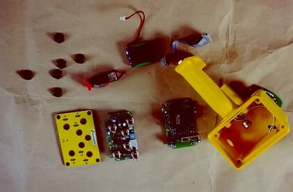
Click to zoom
Application Details
- Equipment Class
- DXT - Part 15 Low Power Transceiver, Rx Verified
- Date of Grant
- Sep 06, 2001
- Application Purpose
- Original Equipment
- Date of Application
- Jun 11, 2001
- Equipment Note
- Radio control
- Frequency Range
- 903.33000000 - 921.33000000
- Company
- Sist & Matica S.r.l.
- Country
- Italy
Documents & Files
Document Text
Text extracted from the exhibit documents filed with the FCC. Open a document above to read the original.
Users Manual
FreeHand User’s Manual REV 1.0 24/07/00 USER’S MANUAL FREEHAND FREEHAND SIST&MATICA S.r.l. - 2 - LIST OF CONTENTS 1. GENERAL DESCRIPTION OF THE PRODUCT 2. INSTALLATION 3. USE AND MAINTENANCE 4. TROUBLESHOOTING AND RESOLUTION OF PROBLEMS USER’S MANUAL FREEHAND FREEHAND SIST&MATICA S.r.l. - 3 - 1. GENERAL DESCRIPTION OF THE PRODUCT FreeHand is the remotely-operated radio control switch, which permits to control, with or wireless and in an ergonomic manner, the moving functions of electrically-operated machines or devices. FreeHand is a flexible electronic system; it consists of a Radio control with handle and lever- switches, and a Receiver Unit, suitable to specific operation requirements; it substitutes or integrates the traditional control systems, electric or hydraulics. A version with proportional control is available; by means of a trigger placed on the handle of the radio control, the control strength applied to the proportional element placed downstream the directional parts, may be adjusted, while the machine components are handled at the wanted speed. The electronics of the proportional control permits to directly control the proportional valve, thus removing any need for further control cards. - Microprocessor electronics both on the Radio Control and on the Receiver Unit; - Paneuropean working frequency: 433.92 MHz; - No control relay, rather utilization of steady-state devices capable to protect the electronics in case of breakdown of the part to be controlled; - Direct connection to the solenoid valves; - Built-in circulation diodes; - Protection against polarity reversal; - Power supply: - Radio control: 4.8 Volt rechargeble battery; - Receiver unit: 12/24 Volts d.c. USER’S MANUAL FREEHAND FREEHAND SIST&MATICA S.r.l. - 4 - DESCRIPTION OF THE RADIO CONTROL The radio control Series FreeHand is power supplied by a 4.8 Volt rechargeble battery, which automatically powers up immediately when any one of the control switches is moved. To give a command to the receiver unit, the switch corresponding to the wanted movement has to be moved. When a switch is operated, a LED placed at the top of the radio control lights up for a split second to signal that the command transmission has started; the same LED turns on immediately when the switch is released. To make wire comunication is necessary to connect the radio control to the receiver group with the elicoidal wire. In this way the radio trasmission is desabled and the wire comunication is enabled to allow to work in particular zone where the radio transmission isn’t consented. USER’S MANUAL FREEHAND FREEHAND SIST&MATICA S.r.l. - 5 - DESCRIPTION OF THE RECEIVER UNIT The receiver unit Series FreeHand may be 12 VDC or 24 VDC (this latter on request) power supplied, through a connection to the battery of the means where it’s installed. Function of the receiver unit FreeHand is receiving the signals from the radio control and to transform them into commands given to the solenoid valves of the electro-hydraulic distributor. USER’S MANUAL FREEHAND FREEHAND SIST&MATICA S.r.l. - 6 - 2. INSTALLATION - Location of the receiver unit - Drilling template - Connecting instructions USER’S MANUAL FREEHAND FREEHAND SIST&MATICA S.r.l. - 7 - LOCATION OF THE RECEIVER UNIT To insure a good reception, the receiver unit FreeHand has to be positioned as shown on the figure below (CORRECT POSITION), with aerial on sight. USER’S MANUAL FREEHAND FREEHAND SIST&MATICA S.r.l. - 8 - DRILLING TEMPLATE The drilling template (in mm) shown on the figure below has to be used for fixing the receiver unit FreeHand to the equipment. 168 149 USER’S MANUAL FREEHAND FREEHAND SIST&MATICA S.r.l. - 9 - CONNECTING INSTRUCTIONS Sample connection of a 16-pin connector: Pin 1 EV 1 Pin 2 EV 2 Pin 3 EV 3 Pin 4 EV 4 Pin 5 EV 5 Pin 6 EV 6 Pin 7 EV 7 Pin 8 EV 8 Pin 9 EV 9 Pin 10 EV 10 Pin 11 Lamp Pin 12 Proportional EV Pin 13 Proportional EV Pin 14 Emergency Stop Pin 15 Emergency Stop Pin 16 Battery + GND Battery - / EV Common Sample connection of a 6-pin connector: Pin 1 Bozzello Pin 2 Pressostato Pin 3 Common Inputs Pin 4 EM 1 Pin 5 EM 2 Pin 6 Battery + GND Battery - USER’S MANUAL FREEHAND FREEHAND SIST&MATICA S.r.l. - 10 - 3. USE AND MAINTENANCE - Description of the control keypad - Preliminary operations - Safety rules - Recharge of the battery USER’S MANUAL FREEHAND FREEHAND SIST&MATICA S.r.l. - 11 - DESCRIPTION OF THE CONTROL KEYPAD 1. Control Lever 1 (Up/Down) 2. Control Lever 2 (Up/Down) 3. Control Lever 3 (Up/Down) 4. Control Lever 4 (Up/Down) 5. Control Lever 5 (Up/Down) 6. Control Lever 6 (Up/Down) PRELIMINARY OPERATIONS This section describes the checking to be performed before starting to use the FreeHand system. - Check the emergency stop mushroom head push button is released; - Check the proportional solenoid valve is working correctly; - Check the consistency of the radio control switches (see under DESCRIPTION OF THE CONTROL KEYPAD) with the commands executed by the utilities. In case of consistency failure between switch and command or of reversed action, check the connections towards the utilities. USER’S MANUAL FREEHAND FREEHAND SIST&MATICA S.r.l. - 12 - SAFETY RULES In case of anomalies (es. encontrollable movements or not desired commands) press the emergency’s fungus placed in the side of the radio control and to apply to the qualified personal. REPLACEMENT OF THE BATTERY The radio control Series FreeHand is power supplied by a 4.8 Volt rechargeble battery. When the battery is down (LED placed at the top of the radio control lights up by intermittence), it must to be recharged. This operation is make by connecting the radio control to the receiver group (wire comunication). When the radio control is connected, the led placed at the top of the radio control fixed lights up as long as the battery is completely recharged. When the battery is completely recharged the led lights up by intermittence. USER’S MANUAL FREEHAND FREEHAND SIST&MATICA S.r.l. - 13 - 4. TROUBLESHO…
Text truncated - open the document above for the full version.
Block Diagram
File: 154463 Sist&matica S.r.l. 12030 MANTA (CN) – VIA S. PERTINI, 17 TEL. (+39) 175 255700 FAX (+39) 175 255715 Email: info@sistema tica.it Manta, 08 giugno 2001 FREEHAND TRANSMITTER BLOCK DIAGRAM COMMAND PANEL MICROCONTROLLER BATTERY SUPPLY 4.8 V BATTERY CHARGE EX TERN AL S UPPLY 24 V TRAN SMI TTER MODULE TRANSMISSION TO RECEIVER PROPORTIONAL COMMAND
Block Diagram
File: 154467 Sist&matica S.r.l. 12030 MANTA (CN) – VIA S. PERTINI, 17 TEL. (+39) 175 255700 FAX (+39) 175 255715 Email: info@sistema tica.it Manta, 08 giugno 2001 OSCILLATOR BLOCK DIAGRAM TRANSMITTER FREEHAND QUARZ OSCILLATOR 8 MHz MICROCONTROLLER DA TA TO TRN SMI TT TXM-900-HP-II (TRANSMITTER MODULE) Modulation Low Pa ss Filte r Modulation in Re fe re nce VCXO Precision 12.00 MHz Crystal Phase-Locked Loop 12.00 MHz FREF 902-928 MHz V.C.O. Output Amp lifier Armonic Filte r Antenna Port M icroco ntro ller Channel Select Lines
External Photos
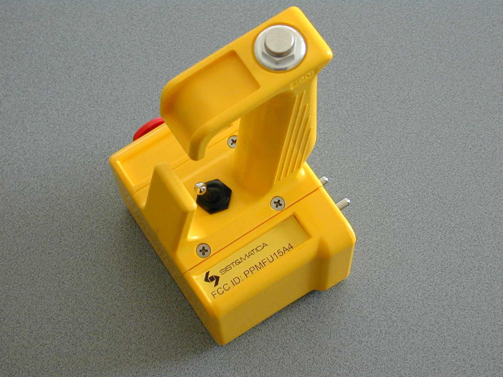
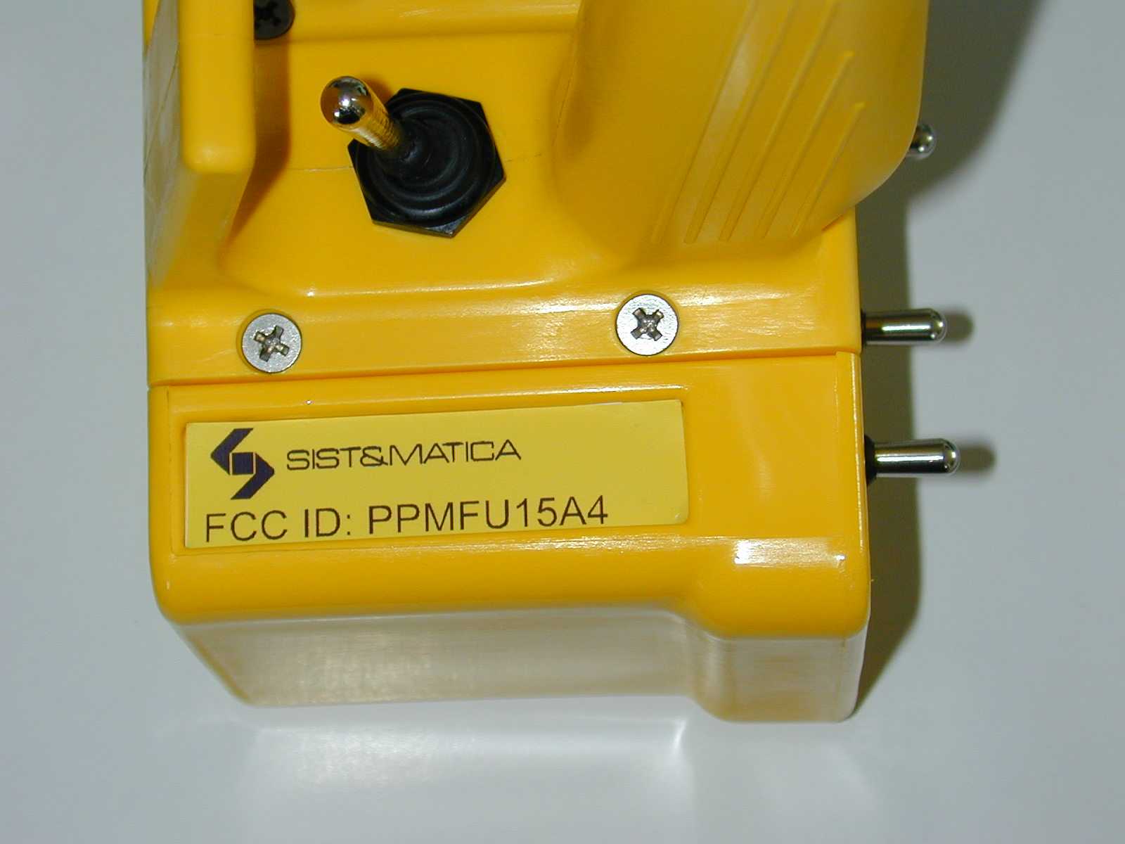
File: 154462 External view of the appliance The appliance closed The appliance open
ID Label/Location Info
FCC ID Location informations
Internal Photos
File: 154461 Internal View of the appliance R F boa rd Co mpo ne nt si de R F boa rd Sol de r s i de File: 154461 Switc h boa rd co mpo ne nt si de Switc h boa rd sol de r si de
Test Report
CiaoLab eTechnology Standard Compliance Services FCC CFR 47 PART 15 Subpart C E.M.I. TEST REPORT Test report No................ :01NM003EM-R01 Prepared by.................... :C. CarùSignature .................................... Approved by...................:G. BaroniSignature .................................... Date of issue................... :June 8, 2001 Number of pages............ :19 Test Laboratory Name..............................:CiaoLab eTechnology S.p.A. - Standard Compliance Services Address.......................... :Via ai Laboratori Olivetti, 79 - 20010 Pregnana Milanese (MI) - I Applicant for the test Name................................................ :SIST&MATICA S.r.l. Equipment under test Model................................................ :FREEHAND – FU15A4 Serial Number................................... :213213 Trade Mark....................................... :SIST&MATICA Manufacturer.....................................:SIST&MATICA S.r.l. Via S. Pertini, 17 12030 Manta - (Cuneo)Italy Rating’s............................................. :2.5VDC ÷ 8VDC Operating temperature range............ :From -20°C to +55°C Equipment information Equipment category.......................... :Radio CONTROLS Classification of the equipment........ :Intentional Radiator Weight............................................... :About 0.6Kg Tested for IT power system.............. :No Test specification Applicable standard.......................... :FCC CFR 47 - Part 15 - Subpart C - § 15.249 Additional installation requirements :No Test results Summary of test results..................... : COMPLIANT Legend:..............................................:NA: Not Applicable - P: Pass - F: Fail Date: June 8, 2001Test report No: 01NM003EM-R01 Page 2 of 19 CiaoLab eTechnology Standard Compliance Services General Remarks The test results presented in this report related only to the item tested. This test report shall not be reproduced except in full without the written approval of the testing laboratory. As stated in FCC §2.902: Verification attaches to all items subsequently marketed by the manufacturer or importer which are identical as defined in §2.908 to the sample tested and found acceptable by the manufacturer. In order to clarify the identical concept the §2.908 states: As used in this subpart the term identical means identical within the variation that can be expected to arise as a result of quantity production techniques. General Information of the Appliance Manufacturer SIST&MATICA S.r.l.Via S. Pertini, 17 12030 Manta (Cuneo) - Italy Applicant for Certification SIST&MATICA S.r.l.Via S. Pertini, 17 12030 Manta (Cuneo) - Italy FCC ID PPMFU15A4 Official of the Responsible party for Certification Name Claudio ArcanoTechnical Director Signature.................................... Description of the Appliance FreeHand is the remotely-operated radio CONTROLS switch, which permits to CONTROLS, with or wireless and in an ergonomic manner, the moving functions of electrically-operated machines or devices. It consists of a Radio CONTROLS with handle and lever-switches, and a Receiver Unit, suitable to specific operation requirements; it substitutes or integrates the traditional CONTROLS systems, electric or hydraulics. A version with proportional CONTROLS is available; by means of a trigger placed on the handle of the radio CONTROLS, the CONTROLS strength applied to the proportional element placed downstream the directional parts, may be adjusted, while the machine components are handled at the wanted speed. Date: June 8, 2001Test report No: 01NM003EM-R01 Page 3 of 19 CiaoLab eTechnology Standard Compliance Services Hereafter are described the mains characteristics of the appliance. - Microprocessor electronics both on the Radio CONTROLS and on the Receiver Unit. - Working frequency: It is possible to select up to 8 different channels w orking at the follow ing frequencies: Switch PositionFre que ncy 0921.33 1919.88 2915.33 3912.33 4909.33 5907.83 6906.33 7903.33 8921.33 9919.83 - - No CONTROLS relay, rather utilization of steady-state devices capable to protect the electronics in case of breakdown of the part to be CONTROLSled; - - Direct connection to the solenoid valves; - - Built-in circulation diodes; - - Protection against polarity reversal; - - Power supply: - - Radio CONTROLS: 4.8 Volt rechargeable battery; - - Receiver unit: 12/24 Volts d.c. The radio CONTROLS Series FreeHand is power supplied by a 4.8 Volt rechargeable battery, which automatically powers up immediately when any one of the CONTROLS switches is moved. To give a command to the receiver unit, the switch corresponding to the wanted movement has to be moved. When the switch is activated the unit generate the RF signal that remains active until the switch is released. When a switch is operated, a LED placed at the top of the radio CONTROLS lights up for a split second to signal that the command transmission has started; the same LED turns on immediately when the switch is released. To make wire communication is necessary to connect the radio CONTROLS to the receiver group with the elicoidal wire. In this way the radio transmission is disabled and the wire communication is enabled to allow to work in particular zone where the radio transmission isn’t allowed. Date: June 8, 2001Test report No: 01NM003EM-R01 Page 4 of 19 CiaoLab eTechnology Standard Compliance Services The appliance submitted to test is the top of a family of devices, the one tested is equipped with 6 switches that allow 12 different operating of the solenoid valves, there are also different configurations with just 4 switches and 2 switches, the differences between the 6 switch version and the 4 / 2 switch version consisting in the absence of the switches in the board defined as “Switch board”. Considering that the circuit generating the RF signal is exactly the same in all the configurations and that a preliminary analysis demonstrate that the RF …
Text truncated - open the document above for the full version.
Test Setup Photos
File: 154460 Test Setup
Contact Information
Applicant
Claudio Arcano(Mr)
Technical Contact
Ciao Lab S.p.A.Carlo Caru'
[email protected]+39 02 23033087
Via S.Pertini, 17 · Pregnana Milanese (Milano) · Italy
Non-Technical Contact
SIST&MATICA S.r.l.Claudio Arcano
[email protected]+39 0175 255700
Test Firm
Ciao Lab S.p.A.Carlo Caru
Technical Specifications
| # | Rule Parts | Frequency Range | Power Output |
|---|---|---|---|
| 1 | 15C | 903.33 MHz - 921.33 MHz | - |
Other Applications from Sist & Matica S.r.l.
PPMRXEASY4
Apr 09, 2007Receiver Radio Control
Equipment Class
CYY - Communications Receiver used w/Pt 15 Transmitter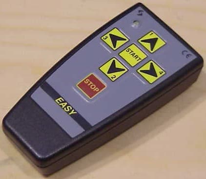
PPMTXEASY4
Apr 09, 2007Transmitter Radio Control
Equipment Class
DSC - Part 15 Security/Remote Control Transmitter