PPMRXEASY4Receiver Radio Control
Sist & Matica S.r.l.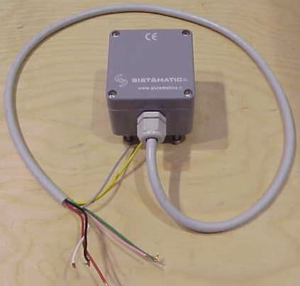
Click to zoom
Application Details
- Equipment Class
- CYY - Communications Receiver used w/Pt 15 Transmitter
- Date of Grant
- Apr 09, 2007
- Application Purpose
- Original Equipment
- Date of Application
- Apr 09, 2007
- Equipment Note
- Receiver Radio Control
- Frequency Range
- 433.92000000 - 433.92000000
- Company
- Sist & Matica S.r.l.
- Country
- Italy
Documents & Files
Document Text
Text extracted from the exhibit documents filed with the FCC. Open a document above to read the original.
Users Manual
SIST&MATICA Srl SIST&MATICA SrlSIST&MATICA Srl SIST&MATICA Srl Pag. 1 Via S. Pertini, 17 - 12030 MANTA (CN) ITALY Tel. +39 0175 255.700 r.a. - Fax +39 0175 255.715 http://www.sistematica.it e-mail: [email protected] ...RADIO REMOTE CONTROL RECEIVERS USER AND MAINTENANCE MANUAL WARNINGS This manual is an essential part of the device and it should be thoroughly kept for later consultation. Carefully read the warnings contained in this manual, concerning safety and a proper preservation of the product. These warnings are ALWAYS to be carefully read before using the device. SIST&MATICA S.r.l. declines all responsibility for any trouble arising from the non-compliance with these warnings. • DO NOT TRAVEL WITH THE DEVICE SWITCHED ON • CONNECT THE SYSTEM ONLY TO THE VEHICLE’S BATTERY • BEFORE CARRYING OUT ANY MECHANICAL MAINTENANCE OPERATION (WELDING) ON THE VEHICLE, DISCONNECT THE BATTERY CLIPS. • AVOID ATTEMPTING TO REPAIR THE DEVICE BY YOURSELF. REPAIRS PERFORMED BY UNSKILLED PEOPLE CAN CAUSE SERIOUS DAMAGES OR FAILURES. FOR ASSISTANCE, APPLY TO YOUR LOCAL AUTHORIZED SERVICE CENTRE. USE ONLY ORIGINAL SPARE PARTS. • ALWAYS KEEP AT A SAFE DISTANCE FROM THE MOVING PARTS. SIST&MATICA Srl SIST&MATICA SrlSIST&MATICA Srl SIST&MATICA Srl Pag. 2 Via S. Pertini, 17 - 12030 MANTA (CN) ITALY Tel. +39 0175 255.700 r.a. - Fax +39 0175 255.715 http://www.sistematica.it e-mail: [email protected] TECHNICAL FEATURES • Microprocessor electronics control; • Glass reinforced polyester casing 80x75x55 grade of enclosure IP65; • 12/24 VDC ±10% (10-30 allowed) rating power supply through connection to the vehicle’s battery; • Typical quiescent current: - 18mA a 12Vcc; - 14mA a 24Vcc. • Maximum suppliable current for each channel: 4A • Maximum total suppliable current: 7A SYSTEM CODING It is necessary to code the system only if you have to replace the transmitter unit or if you want to use it with a different receiver from the one it was purchased with. Follow the instructions to code the system: 1. Take the power supply off the receiver (emergency stop button released); 2. Open the receiver box, by unscrewing the 4 screws fixed on its top 3. Locate the coding pushbutton on the receiver board, shown in the picture below. 4. Push the coding button (and keep it pushed); 5. Put power into the receiver (emergency stop button released) keeping the coding pushbutton pushed 6. Wait for a few seconds (3-4 secs) 7. Release the coding pushbutton 8. Press any 3 keys at the same time on the radio control transmitter within 15 seconds since it has been switched on (also more times if it is necessary) 9. Check all the system functions (first, press START to enable the system reception) 10. Close the receiver box; N.B.: The receiver can work with the radio control transmitters type: EASY, TREND and SMART RELAY MOTOR RESETTING The relay motor resetting is an operation to carry out in order to change its coupling with the other outputs (OUT1, OUT2, OUT3...) from the original standard system setting. By a standard system setting when any key is pressed on the radio control transmitter the correspondent output + relay motor output is activated. (see “Instructions for use” in the radio control transmitter manual). N.B.: The resetting operations can be carried out only by using the radio control transmitter Easy or Trend. To change the relay motor output coupling with the output required, it is necessary to act as follows: 1. Open the receiver box, by unscrewing the 4 screws on the top 2. Put power on the receiver (emergency stop button released) 3. Press the coding button (and keep it pushed) on the receiver board (see the picture on the left hand side column) 4. Press START (and keep it pressed) on the radio control transmitter (Easy/Trend type) 5. Release the coding button and the key on the radio control transmitter 6. Activate in a row, by the radio control transmitter, the outputs that are to be coupled with the relay motor. 7. Press the coding button (and keep it pressed) on the receiver’s board. 8. Press STOP (and keep it pressed) on the radio control transmitter. Now the new output + relay motor coupling is recorded 9. Release the coding button and the key on the radio control transmitter 10. Check all the system functioning.. In case any error should occur while resetting the system, it is possible to cancel the operation, by taking the power off the system and repeating the operation. SIST&MATICA Srl SIST&MATICA SrlSIST&MATICA Srl SIST&MATICA Srl Pag. 3 Via S. Pertini, 17 - 12030 MANTA (CN) ITALY Tel. +39 0175 255.700 r.a. - Fax +39 0175 255.715 http://www.sistematica.it e-mail: [email protected] CONNECTING INSTRUCTIONS Description of the 2output receiver + relay motor connection to the users: INPUTS/OUTPUTS LIST CABLE NO. CABLE COLOUR OUT1 1 GREEN OUT2 2 YELLOW RELAY MOTOR 3 WHITE + BATTERY 4 RED - BATTERY YELLOW / GREEN BLACK Description of the 4output receiver+ relay motor connection to the users: INPUTS/OUTPUTS LIST CABLE NO. CABLE COLOUR OUT1 1 GREEN OUT2 2 YELLOW OUT3 3 GREY OUT4 4 PINK RELAY MOTOR 5 WHITE + BATTERY 6 RED - BATTERY YELLOW / GREEN BLACK Description of the 8output receiver+ relay motor connection to the users: INPUTS/OUTPUTS LIST CABLE NO. OUT1 1 OUT2 2 OUT3 3 OUT4 4 OUT 5 5 OUT 6 6 OUT 7 7 OUT 8 8 RELAY MOTOR 10 + BATTERY 11 - BATTERY YELLOW / GREEN DATAPLATES AND THEIR POSITIONING Identification data plate of the receiver. Positioning on the receiver box. N.B.: Removing the identification data plates causes the existing warrantees loss and involves the responsibility of SIST&MATICA S.R.L. to lapse with respect to the competent bodies SIST&MATICA Srl SIST&MATICA SrlSIST&MATICA Srl SIST&MATICA Srl Pag. 4 Via S. Pertini, 17 - 12030 MANTA (CN) ITALY Tel. +39 0175 255.700 r.a. - Fax +39 0175 255.715 http://www.sistematica.it e-mail: [email protected] POSITIONING OF THE RECEIVER UNIT For a proper functioning, locate the receiver EASY with the cable output downwards, as shown in the following picture: …
Text truncated - open the document above for the full version.
Cover Letter(s)
Cert. Nr. 50 100 3249 SIST&MATICA S.r.l. Via S.Pertini 17 – I – 12030 MANTA (CN) – Tel. (+39) 0175 255700 r.a. – Fax (+39) 0175 255715 Internet: www.sistematica.it – Email: [email protected] Cap.Soc. € 100.000 R.E.A. n. 146566 – Reg. Imprese C.C.I.A.A. Cuneo n. 3110 P.IVA 01959190040 Federal Communications Commission 7435 Oakland Mills Road Columbia, MD 21046 Gentlemen: This letter is to comply with Section 0.457(d)(2)(i) pertaining to confidential material. SIST&MATICA S.r.l. would like the following documents regarding this submission for FCC ID: PPM RXEASY4 to be kept confidential. 1. Document: Electrical schematics – SM0043. 2. Document: Bill of materials – SM0044 3. Document: Block diagram – SM0046 4. Document: Operative description – SM0049 The above material contains trade secrets or technical data, which would customarily be guarded from competitors. We do not want these documents to be accessible to the general public. Sincerely,
Test Report
NOTICE: The results of tests and checks reported in this Test Report refer exclusively to the samples tested and described in the Report itself. This report shall not be reproduced partially or in its entirety without the written approval of IMQ S.p.A. IMQ S.p.A. - Via Quintiliano, 43 – I-20138 MILANO T ELECOMMUNICATIONS & T ELEMATICS FOR T RANSPORTS L ABORATORY Telecommunications & Telematics for Transports Lab. TEST REPORT Ref. No. ARSG00133/2 Date: 2007-03-07 Measurements performed in accordance with: FCC Rules: Code of Federal Regulations (CFR) no. 47 - PART 15 – RADIO FREQUENCY DEVICES PRODUCT : Radio control transmitter APPLICANT : SIST&MATICA S.r.l. – Via S.Pertini, 17 – I-12030 Manta MANUFACTURER : SIST&MATICA S.r.l. – Via S.Pertini, 17 – I-12030 Manta TRADEMARK : SIST&MATICA TESTED MODEL : EASY4 FCC ID : PPMRXEASY4 SERIAL NUMBER : 0270107 RATING : DC 12/24 V OTHER INFORMATION : Samples received on : 2006-07-06 Testing dates : 2006-07-06 ÷ 2006-07-07 Samples tested No. : 1 Testing site : IMQ S.p.A:Viale Lombardia, 20 – I-20021 Bollate Tested by : R. Torri Signature: Date : 2007-03-07 Checked by: Ing. C. Cantaluppi (EMC and R&TTE Lab Head) Signature: Date : 2007-03-09 Revision Sheet Release No. Date Revision Description Rev. 0 2006-09-01 Test Results and Evaluation Report Rev. 1 2007-03-07 Test report format and measurement updating TT&T Laboratory Test Report no. ARSG00133/2 Date: 2007-03-07 page 2 of 15 T ELECOMMUNICATIONS & T ELEMATICS FOR T RANSPORTS L ABORATORY CONTENTS 1 TEST SPECIFICATIONS, METHODS & PROCEDURES ...............3 1.1 EMISSION TESTS ........................................................................3 1.2 EQUIPMENT CLASSIFICATION ...................................................3 1.3 ENVIRONMENTAL CONDITIONS ................................................3 2 EQUIPMENT UNDER TEST DETAILS............................................4 2.1 EUT IDENTIFICATION ..................................................................4 2.2 EUT TECHNICAL DATA................................................................5 2.3 TESTED SAMPLES.......................................................................5 2.4 SYSTEM INTERFACE IDENTIFICATION .....................................6 2.5 DESCRIPTION OF SUPPORT EQUIPMENT................................7 3 GENERAL MEASUREMENT CONDITIONS ...................................8 3.1 OPERATION OF THE EQUIPMENT (EUT)...................................8 3.2 EUT PERFORMANCE ASSESSMENT .........................................9 4 SUMMARY OF TEST RESULTS...................................................10 4.1 EMISSION TESTS......................................................................10 5 EMC TEST DATA ..........................................................................11 RADIATED DISTURBANCE AT ENCLOSURE PORT ........................12 6 ADDITIONAL TECHNICAL INFORMATION .................................13 6.1 ELECTROMAGNETICALLY RELEVANT COMPONENTS:.........13 6.2 RFI SUPPRESSION DEVICES: ..................................................13 6.3 EMI PROTECTION DEVICES: ....................................................13 7 TECHNICAL DOCUMENTATION..................................................13 8 PHOTOGRAPHIC DOCUMENTATION .........................................14 8.1 EUT IDENTIFICATION ................................................................14 9 MEASUREMENT AND TEST EQUIPMENT ..................................15 TT&T Laboratory Test Report no. ARSG00133/2 Date: 2007-03-07 page 3 of 15 T ELECOMMUNICATIONS & T ELEMATICS FOR T RANSPORTS L ABORATORY 1 TEST SPECIFICATIONS, METHODS & PROCEDURES The following tests and relevant standards have been applied to the Equipment Under Test (EUT): 1.1 EMISSION TESTS Product family standard Date Title FCC Rules February 1, 2006 Code of Federal Regulations (CFR) no. 47 PART 15 – RADIO FREQUENCY DEVICES 1.2 EQUIPMENT CLASSIFICATION According to the definition 15.3 (o) EUT is a Class B digital device. A digital device that is marketed for use in a residential environment notwithstanding use in commercial, business and industrial environments. Examples of such devices include, but are not limited to, personal computers, calculators, and similar electronic devices that are marketed for use by the general public. Note: The responsible party may also qualify a device intended to be marketed in a commercial, business or industrial environment as a Class B device, and in fact is encouraged to do so, provided the device complies with the technical specifications for a Class B digital device. In the event that a particular type of device has been found to repeatedly cause harmful interference to radio communications, the Commission may classify such a digital device as a Class B digital device, regardless of its intended use so it shall fulfil provisions of 47CFR Part 15 Subpart C – Intentional radiators – Section 15.209 and 15.231. 1.3 ENVIRONMENTAL CONDITIONS TEST CONDITIONS MEASURED Ambient Temperature 20 ÷ 25 °C Relative Humidity 50 ÷ 60 % Atmospheric Pressure 900 ÷ 1000 mbar TT&T Laboratory Test Report no. ARSG00133/2 Date: 2007-03-07 page 4 of 15 T ELECOMMUNICATIONS & T ELEMATICS FOR T RANSPORTS L ABORATORY 2 EQUIPMENT UNDER TEST DETAILS 2.1 EUT IDENTIFICATION The EUT is composed by the following modules/parts: Receiver module EUT classification Unintentional radiator EUT use / installation (fixed/vehicular use/portable use) : Vehicular EUT single or system: Single EUT standing (floor- standing/Table-top-wall- mounted) : --- Dimension of EUT (H x W x D): 80x75x55 mm Weight of EUT: 55 g TT&T Laboratory Test Report no. ARSG00133/2 Date: 2007-03-07 page 5 of 15 T ELECOMMUNICATIONS & T ELEMATICS FOR T RANSPORTS L ABORATORY 2.2 EUT TECHNICAL DATA Power supply: DC 12/24 V (rating power supply through connection to the vehicle’s battery) Power specification --- Working frequency 433.92 MHz Processor --- Main Battery None Main SW identification ---- Main…
Text truncated - open the document above for the full version.
Contact Information
Applicant
Claudio Arcano(Mr)
Test Firm
IMQ S.p.A.Vincenzo La Fragola
Technical Specifications
| # | Rule Parts | Frequency Range | Power Output |
|---|---|---|---|
| 1 | 15B | 433.92 MHz - 433.92 MHz | - |
Other Applications from Sist & Matica S.r.l.
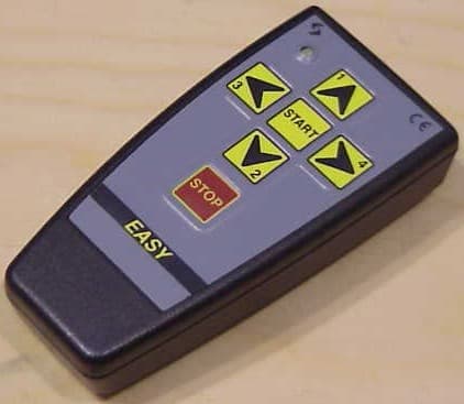
PPMTXEASY4
Apr 09, 2007Transmitter Radio Control
Equipment Class
DSC - Part 15 Security/Remote Control Transmitter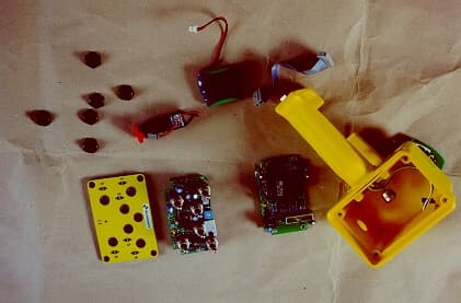
PPMFU15A4
Sep 06, 2001Radio control
Equipment Class
DXT - Part 15 Low Power Transceiver, Rx Verified