PPMTXEASY4Transmitter Radio Control
Sist & Matica S.r.l.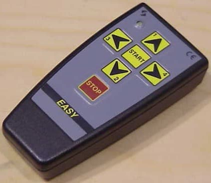
Click to zoom
Application Details
- Equipment Class
- DSC - Part 15 Security/Remote Control Transmitter
- Date of Grant
- Apr 09, 2007
- Application Purpose
- Original Equipment
- Date of Application
- Apr 09, 2007
- Equipment Note
- Transmitter Radio Control
- Frequency Range
- 433.92000000 - 433.92000000
- Company
- Sist & Matica S.r.l.
- Country
- Italy
Documents & Files
Document Text
Text extracted from the exhibit documents filed with the FCC. Open a document above to read the original.
Users Manual
SIST&MATICA Srl SIST&MATICA SrlSIST&MATICA Srl SIST&MATICA Srl Pag. 1 Via S. Pertini, 17 - 12030 MANTA (CN) ITALY Tel. +39 0175 255.700 r.a. - Fax +39 0175 255.715 http://www.sistematica.it e-mail: [email protected] ...RADIO REMOTE CONTROL TRANSMITTERS USER AND MAINTENANCE MANUAL WARNINGS This manual is an essential part of the device and it should be thoroughly kept for later consultation. Carefully read the warnings contained in this manual, concerning safety and a proper preservation of the product. These warnings are ALWAYS to be carefully read before using the device. SIST&MATICA S.r.l. declines all responsibility for any trouble arising from the non-compliance with these warnings. • AVOID ATTEMPTING TO REPAIR THE DEVICE BY YOURSELF. REPAIRS PERFORMED BY UNSKILLED PEOPLE CAN CAUSE SERIOUS DAMAGES OR FAILURES. FOR ASSISTANCE, APPLY TO YOUR LOCAL AUTHORIZED SERVICE CENTRE. USE ONLY ORIGINAL SPARE PARTS. • ALWAYS KEEP AT A SAFE DISTANCE FROM THE MOVING PARTS. • KEEP THE RADIO CONTROL OUT OF THE CHILDREN’S REACH. SIST&MATICA Srl SIST&MATICA SrlSIST&MATICA Srl SIST&MATICA Srl Pag. 2 Via S. Pertini, 17 - 12030 MANTA (CN) ITALY Tel. +39 0175 255.700 r.a. - Fax +39 0175 255.715 http://www.sistematica.it e-mail: [email protected] TECHNICAL FEATURES • Working frequency 433.92 MHz; • Battery supply (no. 2 "AAA" 1,5V Cell, Alkaline Batteries) • Transmission average absorption < 5 mA • Quiescent absorption < 0.2 uA • Average batteries life: 8 mths • Light signals to indicate controls transmission and low battery • IP 67 protected, oil, diluted alkali and acids proof keypad • Up to 4 control functions • Response time after a button push: <35 ms • Emergency stop function response time (stop button): <35 ms • Working temperature: -20°C to + 70°C • Transmitter weight (batteries included): 55 gr. • Working distance in open spaces: 80 m.- 260 ft (with fresh batteries) • Size (in mm): 96 x 47 x 24 INSTRUCTIONS FOR USE 1. Switch the receiver on (emergency stop button released) 2. Wait for a few seconds (self-testing) 3. Press START to allow the system to receive the transmission (the system stays active for n. 2 minutes after the last control has been given, after which it resets. Then press START again to restart the system) 4. Press the required key on the transmitter to activate the related output on the receiver. Ex. KEY 1→ OUT 1 + RELAY MOTOR 5. Press the STOP key to inhibit the controls reception. In this phase all the controls are reset. To activate again the system press START LED INDICATED ON THE RADIO TRANSMITTER REGULAR FUNCTIONING While functioning regularly, the LED flashes when any key is pressed. LOW BATTERY When the battery is low, the LED keeps flashing as far as a key is pressed. At this point, the system will function for a few more time: replace with new batteries (see “TRANSMITTER’S BATTERIES REPLACEMENT”). Do not leave flat batteries inside the transmitter SYSTEM CODING It is necessary to code the system only if you have to replace the transmitter unit or if you want to use it with a different receiver from the one it was purchased with. To recode the system refer to the receiver user manual SIST&MATICA Srl SIST&MATICA SrlSIST&MATICA Srl SIST&MATICA Srl Pag. 3 Via S. Pertini, 17 - 12030 MANTA (CN) ITALY Tel. +39 0175 255.700 r.a. - Fax +39 0175 255.715 http://www.sistematica.it e-mail: [email protected] TRANSMITTER’S BATTERIES REPLACEMENT Due to the electronical microelements of the radio control transmitter, carefully handle the under described operations in a clean environment. 1. Use n. 2 “AAA” 1,5 V type alkaline batteries (due to the low radio control transmitter consumption it is not advisable to use carbon zinc batteries as they can undergo self-discharge more rapidly than alkaline ones. Do not use rechargeable batteries) 2. Open the transmitter case by screwing the screw located on its back, as the arrow indicates in the above picture; 3. Open the transmitter: the keypad is connected to the lower part of the transmitter by a flexible conductor: handle it carefully to avoid it to come out; 4. Turn the keypad cover of 90° 5. Unscrew the screw that keeps the batteries locked, as the arrows indicates in the above picture, and take it off (see the following picture) SIST&MATICA Srl SIST&MATICA SrlSIST&MATICA Srl SIST&MATICA Srl Pag. 4 Via S. Pertini, 17 - 12030 MANTA (CN) ITALY Tel. +39 0175 255.700 r.a. - Fax +39 0175 255.715 http://www.sistematica.it e-mail: [email protected] 6. Take the discharged batteries off. 7. Put the new batteries in, taking care of the polarity indicated next to every contact. Before closing the battery case, check that the LED flashes when any key is pressed and released on the transmitter. If this should not happen, check the correct positioning of the batteries. 8. Close the battery case by following backwards the instructions given. TROUBLESHOOTING AND SOLUTIONS PROBLEM POSSIBLE CAUSE SOLUTION The led on the radio control transmitter does not flash when pressing any key Flat battery Replace the radio control transmitter battery The system does not react to any command Flat battery Replace the radio control transmitter battery The system does not react to any command Wrong replacement of the batteries Check the correct batteries positioning The system does not react to any command System coding loss Code again the system following the instructions related only to the correspondent receiver’s coding. The system reacts to any command in a not continuous way Flat battery Replace the radio control transmitter battery The system reacts to any command in a not continuous way Transmission out of the radio control transmitter range Keep at a distance ≤ 80m from the receiver “Changes or modifications not expressly approved by the party responsible for compliance could void the user’s authority to operate the equipment”.
Cover Letter(s)
Cert. Nr. 50 100 3249 SIST&MATICA S.r.l. Via S.Pertini 17 – I – 12030 MANTA (CN) – Tel. (+39) 0175 255700 r.a. – Fax (+39) 0175 255715 Internet: www.sistematica.it – Email: [email protected] Cap.Soc. € 100.000 R.E.A. n. 146566 – Reg. Imprese C.C.I.A.A. Cuneo n. 3110 P.IVA 01959190040 Federal Communications Commission 7435 Oakland Mills Road Columbia, MD 21046 Gentlemen: This letter is to comply with Section 0.457(d)(2)(i) pertaining to confidential material. SIST&MATICA S.r.l. would like the following documents regarding this submission for FCC ID: PPM TXEASY4 to be kept confidential. 1. Document: Electrical schematics – SM0042. 2. Document: Bill of materials – SM0045 3. Document: Block diagram – SM0047 4. Document: Operative description – SM0048 The above material contains trade secrets or technical data, which would customarily be guarded from competitors. We do not want these documents to be accessible to the general public. Sincerely,
Test Report
NOTICE: The results of tests and checks reported in this Test Report refer exclusively to the samples tested and described in the Report itself. This report shall not be reproduced partially or in its entirety without the written approval of IMQ S.p.A. IMQ S.p.A. - Via Quintiliano, 43 – I-20138 MILANO T ELECOMMUNICATIONS & T ELEMATICS FOR T RANSPORTS L ABORATORY Telecommunications & Telematics for Transports Lab. TEST REPORT Ref. No. ARSG00133/1 Date: 2007-03-07 Measurements performed in accordance with: FCC Rules: Code of Federal Regulations (CFR) no. 47 - PART 15 – RADIO FREQUENCY DEVICES PRODUCT : Radio control transmitter APPLICANT : SIST&MATICA S.r.l. – Via S.Pertini, 17 – I-12030 Manta MANUFACTURER : SIST&MATICA S.r.l. – Via S.Pertini, 17 – I-12030 Manta TRADEMARK : SIST&MATICA TESTED MODEL : EASY4 FCC ID : PPMTXEASY4 SERIAL NUMBER : 0270107 RATING : DC 2 x 1.5 V size AAA alkaline battery OTHER INFORMATION : Samples received on : 2007-03-01 Testing dates : 2007-03-06 ÷ 2007-03-07 Samples tested No. : 1 Testing site : IMQ S.p.A – Via Quintiliano, 43 I-20138 MILANO Tested by : R. Torri Signature: Date : 2007-03-07 Checked by: R. Colombo (EMC and R&TTE Lab. deputy) Signature: Date : 2007-03-09 Revision Sheet Release No. Date Revision Description Rev. 0 2006-09-01 Test Results and Evaluation Report Rev. 1 2007-03-07 Test report format and measurement updating TT&T Laboratory Test Report No. ARSG00133/1 Date: 2007-03-07 page 2 of 24 T ELECOMMUNICATIONS & T ELEMATICS FOR T RANSPORTS L ABORATORY CONTENTS 1 TEST SPECIFICATIONS, METHODS & PROCEDURES ...............2 1.1 EMISSION TESTS ........................................................................3 1.2 EQUIPMENT CLASSIFICATION ...................................................3 1.3 ENVIRONMENTAL CONDITIONS ................................................3 2 EQUIPMENT UNDER TEST DETAILS............................................4 2.1 EUT IDENTIFICATION ..................................................................4 2.2 EUT TECHNICAL DATA................................................................5 2.3 TESTED SAMPLES.......................................................................5 2.4 SYSTEM INTERFACE IDENTIFICATION .....................................6 2.5 DESCRIPTION OF SUPPORT EQUIPMENT................................6 3 GENERAL MEASUREMENT CONDITIONS ...................................7 3.1 OPERATION OF THE EQUIPMENT (EUT)...................................7 3.2 EUT PERFORMANCE ASSESSMENT .........................................8 4 SUMMARY OF TEST RESULTS.....................................................9 4.1 EMISSION TESTS ........................................................................9 5 EMC TEST DATA ..........................................................................10 6 ADDITIONAL TECHNICAL INFORMATION .................................21 6.1 ELECTROMAGNETICALLY RELEVANT COMPONENTS:.........21 6.2 RFI SUPPRESSION DEVICES: ..................................................21 6.3 EMI PROTECTION DEVICES: ....................................................21 7 TECHNICAL DOCUMENTATION..................................................21 8 PHOTOGRAPHIC DOCUMENTATION .........................................22 8.1 EUT IDENTIFICATION ................................................................22 9 MEASUREMENT AND TEST EQUIPMENT ..................................24 1 TEST SPECIFICATIONS, METHODS & PROCEDURES The following tests and relevant standards have been applied to the Equipment Under Test (EUT): TT&T Laboratory Test Report No. ARSG00133/1 Date: 2007-03-07 page 3 of 24 T ELECOMMUNICATIONS & T ELEMATICS FOR T RANSPORTS L ABORATORY 1.1 EMISSION TESTS Product family standard Date Title FCC Rules February 1, 2006 Code of Federal Regulations (CFR) no. 47 PART 15 – RADIO FREQUENCY DEVICES 1.2 EQUIPMENT CLASSIFICATION According to the definition 15.3 (o) EUT is a Class B digital device. A digital device that is marketed for use in a residential environment notwithstanding use in commercial, business and industrial environments. Examples of such devices include, but are not limited to, personal computers, calculators, and similar electronic devices that are marketed for use by the general public. Note: The responsible party may also qualify a device intended to be marketed in a commercial, business or industrial environment as a Class B device, and in fact is encouraged to do so, provided the device complies with the technical specifications for a Class B digital device. In the event that a particular type of device has been found to repeatedly cause harmful interference to radio communications, the Commission may classify such a digital device as a Class B digital device, regardless of its intended use so it shall fulfil provisions of 47CFR Part 15 Subpart C – Intentional radiators – Section 15.231 and 15.209. 1.3 ENVIRONMENTAL CONDITIONS TEST CONDITIONS MEASURED Ambient Temperature 20 ÷ 25 °C Relative Humidity 50 ÷ 60 % Atmospheric Pressure 900 ÷ 1000 mbar TT&T Laboratory Test Report No. ARSG00133/1 Date: 2007-03-07 page 4 of 24 T ELECOMMUNICATIONS & T ELEMATICS FOR T RANSPORTS L ABORATORY 2 EQUIPMENT UNDER TEST DETAILS 2.1 EUT IDENTIFICATION The EUT is composed by the following modules/parts: Transmitter module 433,92 MHz EUT classification Intentional radiator EUT use / installation (fixed/vehicular use/portable use) : Portable EUT single or system: Single EUT standing (floor- standing/Table-top-wall- mounted) : --- Dimension of EUT (H x W x D): 96 x 47 x 25 mm Weight of EUT: --- TT&T Laboratory Test Report No. ARSG00133/1 Date: 2007-03-07 page 5 of 24 T ELECOMMUNICATIONS & T ELEMATICS FOR T RANSPORTS L ABORATORY 2.2 EUT TECHNICAL DATA Power supply : DC 2 x 1.5 V size AAA alkaline battery Power specification : --- Working frequency : 433.92 MHz Modulation : --- Bit rate : --- RX Sensitivity : --- Processor : --- Main Battery : --- Main SW identification : --- M…
Text truncated - open the document above for the full version.
Contact Information
Applicant
Claudio Arcano(Mr)
Test Firm
IMQ S.p.A.Vincenzo La Fragola
Technical Specifications
| # | Rule Parts | Frequency Range | Power Output |
|---|---|---|---|
| 1 | 15.231 | 433.92 MHz - 433.92 MHz | - |
Other Applications from Sist & Matica S.r.l.
PPMRXEASY4
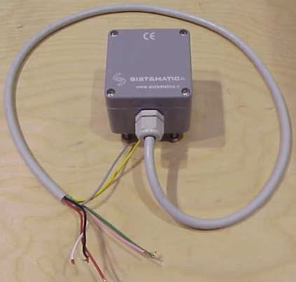
Apr 09, 2007Receiver Radio Control
Equipment Class
CYY - Communications Receiver used w/Pt 15 Transmitter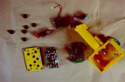
PPMFU15A4
Sep 06, 2001Radio control
Equipment Class
DXT - Part 15 Low Power Transceiver, Rx Verified