PQ4IPROS401Mobile Phone
HONG KONG IPRO TECHNOLOGY CO.,LIMITED
Click to zoom
Application Details
- Equipment Class
- JBP - Part 15 Class B Computing Device Peripheral
- Date of Grant
- Nov 12, 2020
- Application Purpose
- Original Equipment
- Date of Application
- Nov 12, 2020
- Equipment Note
- Mobile Phone
- Country
- China
Documents & Files
Document Text
Text extracted from the exhibit documents filed with the FCC. Open a document above to read the original.
Users Manual
Quick starter guide Device location diagram To turn on the device, press the switch button for 2-3 seconds. Battery Charging Batteries must be charged before they are first used. When charging, the charger should be close to the power socket and easy to unplug. Insert card descriptionThis will prevent the phone from being recognized or causing damage to the card slot. In case the phone cannot be recognized or the card slot is damaged. In order to avoid the cell phone can not identify or cause damage to the card slot. Dual Sim dual standby security information According to your mood of dual sim dual standby management, work and life are great. In the setting interface, click SIM card management, select 3G card slot settings according to needs, and easily switch 3G networks Dual card dual standby single channel instructions Your mobile phone adopts the design of “dual sim dual standby” and the two cards inserted into the phone can’t use voice services or data services at the same time When one of the cards is on a call, the other card can’t answer the phone. If someone just dials another card at the moment, you may hear voice prompts such as”the number you dialed is not in service area”The user you dialed can’t be connected temporarily, please dial later”. When one of the cards is using data services, the data services of the other card can’t be used. The above situation is a single channel feature of the mobile phone, which can significantly reduce power consumption, improve standby time, and has nothing to do with the network status of operators. Before using the device, please read all safety information to ensure safe and correct use. Use of an unapproved or incompatible power supply, charger or battery that may cause fire, explosion or other hazard. When charging the device, the power sockets should be installed near the device and easily accessible. When charging is complete or not, please disconnect the charger from the device and remove the charging from the power socket If the device is equipped with a non-removable internal battery, do not replace the battery by yourself to avoid damaging to battery or device. The battery can only be replaced by authorized service center. Please dispose the equipment, batteries and other accessories according to local regulations and do not treat them as domestic waste disposal. Batteries may explode if improperly disposed of. If other types of accessories are used, it may violate the warranty terms of the device and relevant provisions of the country where the device is located, and may lead to safety accidents. For approved accessories, please contact the authorized service center. In order to prevent possible hearing damage, do not use high volume for a long time. Please use the device in the temperature range of 0 °C-35 °C, and store the device and accessories in the temperature range of -20 °C-45 °C. When the ambient temperature is too high or too low, it may cause device failure. Do not expose the device and batteries to high temperature or heating device, such as sunshine, heater, microwave oven, oven or water heater. Overheating of the battery may cause an explosion. ! Do not flashing by yourself If the user adds the third-party ROM system or modifies the system files by cracking, the system maybe unstable and may bring security risks and threats. IPRO will not be responsible for these situations. This device uses standard Nano-SIM and micro-SIM cards. If you need to replace or purchase SIM cards, please contact the network operator. Insert the needle into the small hole on the SIM card tray and pop up the card tray. Please insert the SIM card as shown in the picture. Front camera Rear camera Recelver Flash light Volume Key+ Volume Key- Power Key Speaker menu home back Earphone jackUSB jack S401 the cell broadcast Enter Message menu to view Broadcast list The purpose of cell broadcasting is to inform mobile phone users of the danger, such as serious threats, child abduction and so on, through some alerts issued by operators,the function is activated by default FCC Warning Specific Absorption Rate (SAR) information SAR tests are conducted using standard operating positions accepted by the FCC with the phone transmitting at its highest certified power level in all tested frequency bands, although the SAR is determined at the highest certified power level, the actual SAR level of the phone while operating can be well below the maximum value, in general, the closer you are to a wireless base station antenna, the lower the power output. Before a new model phone is a available for sale to the public, it must be tested and certified to the FCC that it does not exceed the exposure limit established by the FCC, Tests for each phone are performed in positions and locations (e.g. at the ear and worn on the body)as required by the FCC. For body worn operation, this mobile phone has been tested and meets the FCC RF exposure guidelines when used with an accessory designated for this product or when used with an accessory that contains no metal and that positions the handset a minimum of 1.0cm from the body. pursuant to part 15 of the FCC Rules. These limits are designed to provide reasonable protection against harmful interference in a residential installation. This equipment generates uses and can radiate radio frequency energy and, if not installed and used in accordance with the instructions, may cause harmful interference to radio communications. However, there is no guarantee that interference will not occur in a particular installation. If this equipment does cause harmful interference to radio or television reception, which can be determined by turning the equipment off and on, the user is encouraged to try to This device complies with part 15 of the FCC Rules. Operation is subject to the following two conditions: (1) This device may not cause harmful interference, and (2) this device must accept any interference received, including interference…
Text truncated - open the document above for the full version.
Cover Letter(s)
QA-FR-170-B HONG KONG IPRO TECHNOLOGY CO.,LIMITED ADD: 12/F 3 LOCKHART ROAD WANCHAI HK TEL: 0755-83829199 FAX: 0755-83828199 E-mail: [email protected] FCC Authorization Date: 2020-10-21 FEDERAL COMMUNICATIONS COMMISSION Authorization and Evaluation Division 7435 Oakland Mills Road Columbia, MD 21046 Subject: Agent Authorization To whom it may concern: We , HONG KONG IPRO TECHNOLOGY CO.,LIMITED, Hereby authorizes Bay Area Compliance Laboratories Corporation to act on its behalf in all matters relating to application for Equipment authorization, including the signing of all documents relating to these matters. All acts carried out by Bay Area Compliance Laboratory Corporation on our behalf shall have the same effect as our own action. We, the undersigned, hereby certify that we are not subject to a denial of federal benefits, that includes FCC benefits, pursuant to Section 5301 of the Anti-Drug Abuse Act of 1988, 21 U.S.C. 862. This authorization is valid until further written notice from the applicant. Sincerely Yours, Client’s signature SAM HUANG Project VP
Cover Letter(s)
QA-FR-171-A HONG KONG IPRO TECHNOLOGY CO.,LIMITED ADD: 12/F 3 LOCKHART ROAD WANCHAI HK TEL: 0755-83829199 FAX: 0755-83828199 E-mail: [email protected] FCC Confidential Authorization Date: 2020-10-21 FEDERAL COMMUNICATIONS COMMISSIONS Authorization and Evaluation Division 7435 Oakland Mills Road Columbia, MD 21046 Subject: Confidentiality Request regarding application for certification of FCC ID: PQ4IPROS401 In accordance with Sections 0.457 and 0.459 of the Commission’s Rules, (HONG KONG IPRO TECHNOLOGY CO.,LIMITED) hereby requests long-term confidential treatment of information accompanying this application as outlined below: Block Diagram Schematics Operation Description Parts List/Tune up procedure (for licensed devices) The above materials contain proprietary and confidential information not customarily released to the public. The public disclosure of these materials provides unjustified benefits to its competitors in the market. Sincerely, Signature: SAM HUANG Project VP
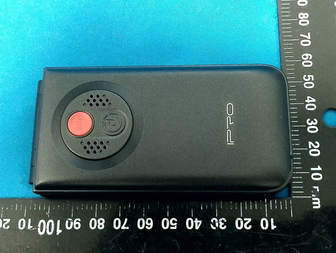
External Photos
EXHIBIT B - EUT EXTERNAL PHOTOGRAPHS
Internal Photos
EXHIBIT C - EUT INTERNAL PHOTOGRAPHS 2G &3G Antenna Wifi & BT Antenna
Test Report
FCC PART 15B TEST REPORT For HONG KONG IPRO TECHNOLOGY CO.,LIMITED 12/F 3 LOCKHART ROAD WANCHAI HK FCC ID: PQ4IPROS401 Report Type: Original Report Product Type: Mobile Phone Report Number: RDG200924011-00B Report Date: 2020-10-20 Reviewed By: Ivan Cao Assistant Manager Test Laboratory: Bay Area Compliance Laboratories Corp. (Dongguan) No.69 Pulongcun, Puxinhu Industry Area, Tangxia, Dongguan, Guangdong, China Tel: +86-769-86858888 Fax: +86-769-86858891 www.baclcorp.com.cn Bay Area Compliance Laboratories Corp. (Dongguan) Report No.: RDG200924011-00B Page 2 of 18 TABLE OF CONTENTS General Information ...................................................................................................................................................... 3 PRODUCT DESCRIPTION FOR EQUIPMENT UNDER TEST (EUT) ..................................................................................... 3 OBJECTIVE ................................................................................................................................................................... 3 RELATED SUBMITTAL(S)/GRANT(S) ............................................................................................................................. 3 TEST METHODOLOGY .................................................................................................................................................. 3 MEASUREMENT UNCERTAINTY .................................................................................................................................... 4 TEST FACILITY ............................................................................................................................................................. 4 DECLARATIONS ............................................................................................................................................................ 4 System Test Configuration ............................................................................................................................................ 5 DESCRIPTION OF TEST CONFIGURATION ...................................................................................................................... 5 EUT EXERCISE SOFTWARE .......................................................................................................................................... 5 SUPPORT EQUIPMENT LIST AND DETAILS .................................................................................................................... 5 SUPPORT CABLE LIST AND DETAILS ............................................................................................................................ 5 BLOCK DIAGRAM OF TEST SETUP ................................................................................................................................ 6 TEST EQUIPMENT LIST ................................................................................................................................................. 7 ENVIRONMENTAL CONDITIONS .................................................................................................................................... 7 Sumary of Test Results .................................................................................................................................................. 8 FCC Part 15B §15.107 – Conducted emissions ........................................................................................................... 9 EUT SETUP .................................................................................................................................................................. 9 EMI TEST RECEIVER SETUP ......................................................................................................................................... 9 TEST PROCEDURE ...................................................................................................................................................... 10 CORRECTED AMPLITUDE & MARGIN CALCULATION ................................................................................................. 10 TEST DATA ................................................................................................................................................................ 10 FCC Part 15B §15.109 – Radiated emissions ............................................................................................................ 13 EUT SETUP ................................................................................................................................................................ 13 EMI TEST RECEIVER SETUP ....................................................................................................................................... 14 TEST PROCEDURE ...................................................................................................................................................... 14 CORRECTED AMPLITUDE & MARGIN CALCULATION ................................................................................................. 14 TEST DATA ................................................................................................................................................................ 14 Bay Area Compliance Laboratories Corp. (Dongguan) Report No.: RDG200924011-00B Page 3 of 18 GENERAL INFORMATION Product Description for Equipment under Test (EUT) EUT Name: Mobile Phone EUT Model: S401 Highest Operation Frequency: 2480 MHz Rated Input Voltage: DC 3.7V from battery or DC 5V from adapter Adapter Information Model: NTR-S01 Input: 100Vac-240Vac 50/60Hz 150mA Output: 5.0Vdc 1000mA Serial Number: RDG200924011-RF-S1 EUT Received Date: 2020.09.28 EUT Received Status: Good Objective This report is prepared on behalf of HONG KONG IPRO TECHNOLOGY CO.,LIMITED in accordance with FCC Part 15B Part 2, Part J, and Part 15, Subpart A and B of the Federal Communications Commis…
Text truncated - open the document above for the full version.
Test Setup Photos
EXHIBIT C - TEST SETUP PHOTOGRAPHS Conducted Emissions Front View Conducted Emissions Side View Radiated Emission Below 1GHz Front View Radiated Emission Below 1GHz Rear View Radiated Emission Above 1GHz Front View Radiated Emission Above 1GHz Rear View
Contact Information
Applicant
Frank Fan(Project VP)
Test Firm
Bay Area Compliance Laboratories Corp.(Dongguan)David Zhang
[email protected]0086 0769 86858888
Technical Specifications
| # | Rule Parts | Frequency Range | Power Output |
|---|---|---|---|
| 1 | 15B | - | - |
Other Applications from HONG KONG IPRO TECHNOLOGY CO.,LIMITED
PQ4IPROV20S
Feb 11, 2026Mobile Phone
Equipment Class
DSS - Part 15 Spread Spectrum Transmitter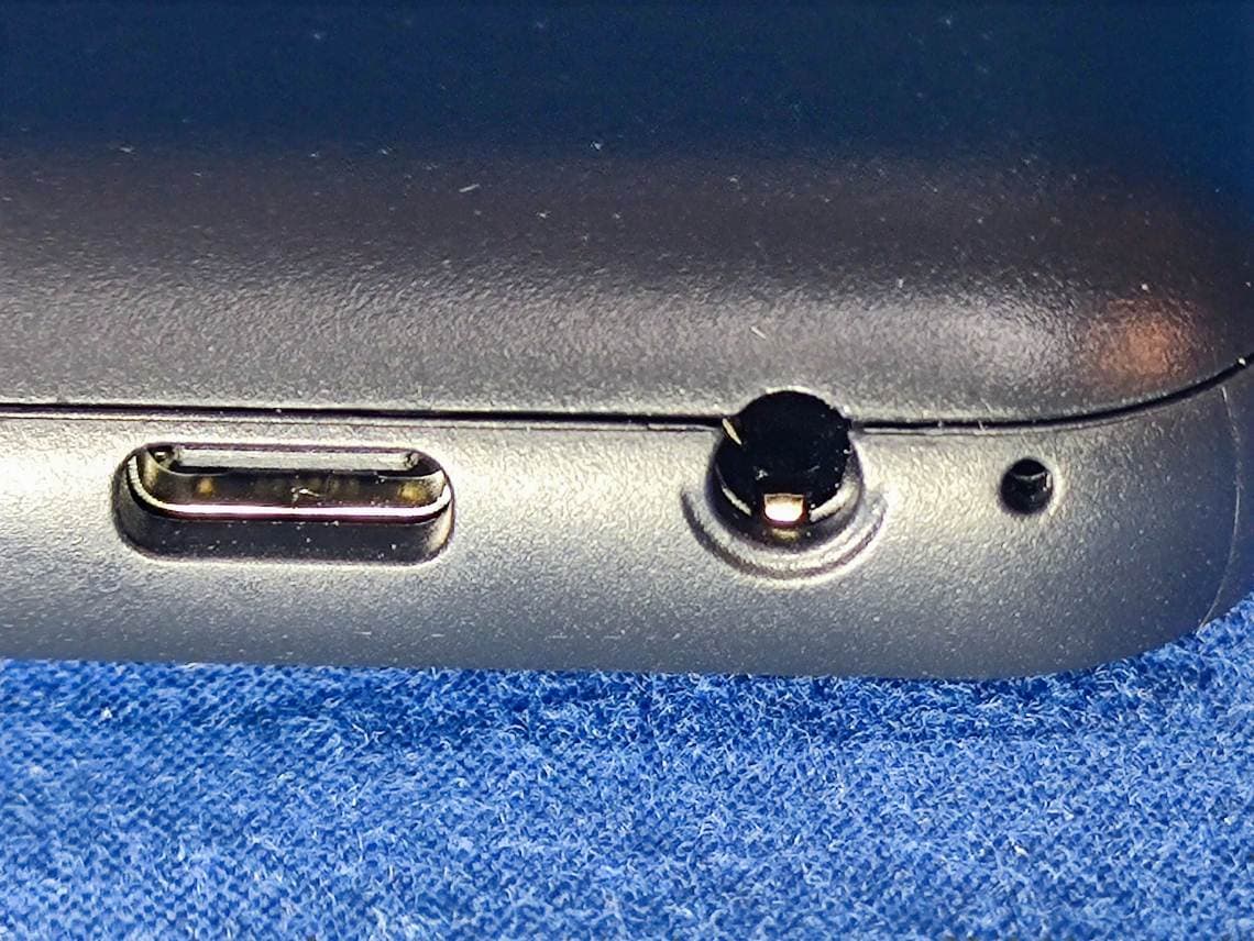
PQ4IPROK3
Jun 16, 2024Mobile Phone
Equipment Class
PCE - PCS Licensed Transmitter held to ear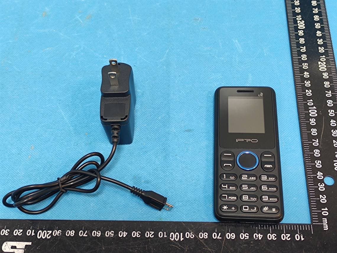
PQ4IPROK5
Jul 23, 2023Mobile Phone
Equipment Class
JBP - Part 15 Class B Computing Device Peripheral
PQ4IPROY300
Apr 13, 2023Smart Phone
Equipment Class
DSS - Part 15 Spread Spectrum Transmitter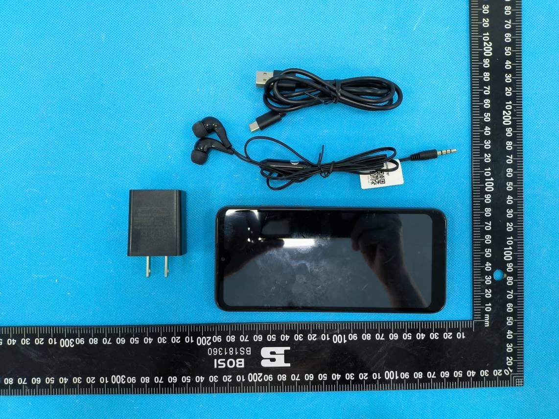
PQ4IPROS300
Nov 06, 2022Smart Phone
Equipment Class
PCE - PCS Licensed Transmitter held to ear