PQ4IPROY300Smart Phone
HONG KONG IPRO TECHNOLOGY CO.,LIMITED
Click to zoom
Application Details
- Equipment Class
- DSS - Part 15 Spread Spectrum Transmitter
- Date of Grant
- Apr 13, 2023
- Application Purpose
- Original Equipment
- Date of Application
- Apr 13, 2023
- Equipment Note
- Smart Phone
- Frequency Range
- 2402.00000000 - 2480.00000000
- Country
- China
Documents & Files
Document Text
Text extracted from the exhibit documents filed with the FCC. Open a document above to read the original.
Users Manual
Y300 FCC WarningSpecific Absorption Rate (SAR) information SAR tests are conducted using standard operating positions accepted by the FCC with the phone transmitting at its highest certified power level in all tested frequency bands, although the SAR is determined at the highest certified power level, the actual SAR level of the phone while operating can be well below the maximum value, in general, the closer you are to a wirelessbase station antenna, the lower the power output.Before a new model phone is a available for sale to the public, it must be tested and certified to the FCC that it does not exceed the exposure limit establishedby the FCC, Tests for each phone are performed inpositions and locations (e.g. at the ear and worn onthe body)as required by the FCC.For body worn operation, this mobile phone has beentested and meets the FCC RF exposure guidelineswhen used with an accessory designated for this product or when used with an accessory that containsno metal and that positions the handset a minimumof 1.0cm from the body. This device complies with part 15 of the FCC Rules. Operation is subject to the following two conditions: (1) This device may not cause harmful interference, and (2) this device must accept any interference received, including interference that may cause undesired operation. Any Changes or modifications not expressly approved by the party responsible for compliance could void the user’s authority to operate the equipment. Note: This equipment has been tested and found to comply with the limits for a Class B digital device, pursuant to part 15 of the FCC Rules. These limits are designed to provide reasonable protection against harmful interference in a residential installation. This equipment generates uses and can radiate radio frequency energy and, if not installed and used in accordance with the instructions, may cause harmful interference to radio communications. However, there is no guarantee that interference will not occur in a particular installation. If this equipment does cause harmful interference to radio or television reception, which can be determined by turning the equipment off and on, the user is encouraged to try to correct the interference by one or more of the following measures:--Reorient or relocate the receiving antenna. --Increase the separation between the equipment andreceiver. --Connect the equipment into an outlet on a circuit different from that to which the receiver is connected. --Consult the dealer or an experienced radio/TV technician for help. Quick starter guide Device location diagramTo turn on the device, press the switch button for 2-3 seconds. Battery ChargingBatteries must be charged before they are first used.When charging, the charger should be close to the power socket and easy to unplug. Insert card description This will prevent the phone from being recognized or causing damage to the card slot.In case the phone cannot be recognized or the card slot is damaged.In order to avoid the cell phone can not identify or cause damage to the card slot.Dual Sim dual standby security information According to your mood of dual sim dual standby management, work and life are great.In the setting interface, click SIM card management, select 4G card slot settings according to needs, and easily switch 4G networksDual card dual standby single channel instructionsYour mobile phone adopts the design of “dual sim dual standby” and the two cards inserted into the phone can’t use voice services or data services at the same timeWhen one of the cards is on a call, the other card can’t answer the phone. If someone just dials another card at the moment, you may hear voice prompts such as”the number you dialed is not in service area”The user you dialed can’t be connected temporarily, please dial later”.When one of the cards is using data services, the data services of the other card can’t be used. The above situation is a single channel feature of the mobile phone, which can significantly reduce power consumption, improve standby time, and has nothing to do with the network status of operators.Before using the device, please read all safety information to ensure safe and correct use.Use of an unapproved or incompatible power supply, charger or battery that may cause fire, explosion or other hazard.When charging the device, the power sockets should be installed near the device and easily accessible.When charging is complete or not, please disconnect the charger from the device and remove the charging from the power socketIf the device is equipped with a non-removable internal battery, do not replace the battery by yourself to avoid damaging to battery or device. The battery can only be replaced by authorized service center.Please dispose the equipment, batteries and other accessories according to local regulations and do not treat them as domestic waste disposal. Batteries may explode if improperly disposed of. If other types of accessories are used, it may violate the warranty terms of the device and relevant provisions of the country where the device is located, and may lead to safety accidents. For approved accessories, please contact the authorized service center.In order to prevent possible hearing damage, do not use high volume for a long time.Please use the device in the temperature range of 0 °C-35 °C, and store the device and accessories in the temperature range of -20 °C-45 °C. When the ambient temperature is too high or too low, it may cause device failure.Do not expose the device and batteries to high temperature or heating device, such as sunshine, heater, microwave oven, oven or water heater. Overheating of the battery may cause an explosion.! Do not flashing by yourselfIf the user adds the third-party ROM system or modifies the system files by cracking, the system maybe unstable and may bring security risks and threats. IPRO will not be responsible for these situations. This device uses standard Nano-SIM and micro-SIM cards. If you …
Text truncated - open the document above for the full version.
External Photos
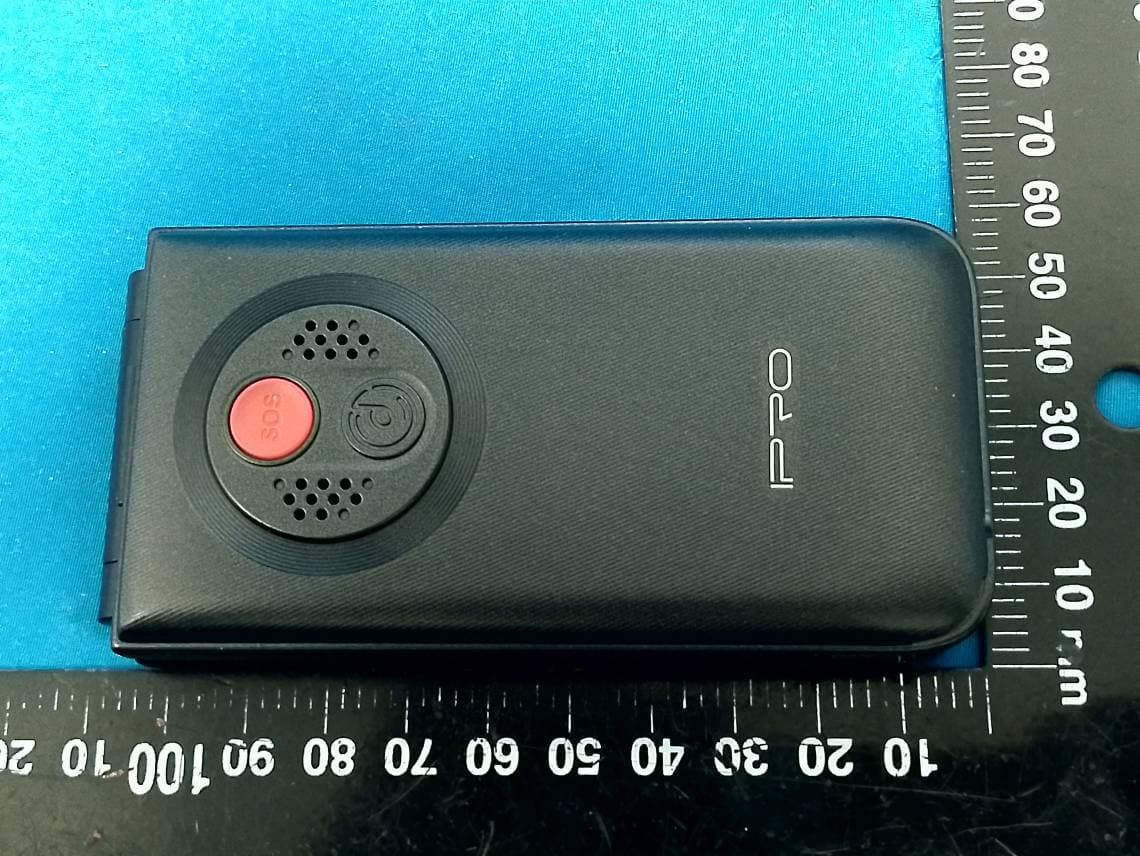
EXHIBIT B - EUT EXTERNAL PHOTOGRAPHS
Internal Photos
EXHIBIT C - EUT INTERNAL PHOTOGRAPHS WWAN DIV Antenna WiFi/Bluetooth Antenna WWAN Main Antenna Battery Label
RF Exposure Info
China Certification ICT Co., Ltd (Dongguan) Report No.: CR230206153-00C Page 58 of 58 5. RF EXPOSURE EVALUATION 5.1 Applicable Standard According to§15.247(i) and §1.1310, systems operating under the provisions of this section shall be operated in a manner that ensure that the public is not exposed to radio frequency energy level in excess of the Commission’s guideline. According to KDB447498 D01 General RF Exposure Guidance v06: The 1-g and 10-g SAR test exclusion thresholds for 100 MHz to 6 GHz at test separation distances ≤ 50 mm are determined by: [(max. power of channel, including tune-up tolerance, mW)/(min. test separation distance, mm)] ꞏ [√f(GHz)] ≤ 3.0 for 1-g SAR and ≤ 7.5 for 10-g extremity SAR, where • f(GHz) is the RF channel transmit frequency in GHz • Power and distance are rounded to the nearest mW and mm before calculation • The result is rounded to one decimal place for comparison • 3.0 and 7.5 are referred to as the numeric thresholds in the step 2 below The test exclusions are applicable only when the minimum test separation distance is ≤ 50 mm and for transmission frequencies between 100 MHz and 6 GHz. When the minimum test separation distance is < 5 mm, a distance of 5 mm according to 5) in section 4.1 is applied to determine SAR test exclusion. 5.2 Measurement Result The max conducted power including tune-up tolerance is 9.0 dBm (7.94 mW). [(max. power of channel, mW)/(min. test separation distance, mm)][√f(GHz)] =7.94/5*(√2.480) = 2.5< 3.0 Result: Compliant. The stand-alone SAR evaluation is not necessary. ===== END OF REPORT =====
Test Report
Heyuan Xunwei Communication Technology Co., Ltd. Antennaspecification 1-1. Antennasizediagram 1-2, Basicprojectinformation Antennatype I955C Frequencyband G900/1800/850/1900+W850/900/1900+FDD B1/2/4/7/8/28 Typeofantenna FPC Companyname Heyuan Xunwei Communication Technology Co., Ltd. Address Zone M, 8/F, Building 1, Baisha New Industrial Park, 3011 Shahe West Road, Nanshan District, Shenzhen 2:Antenna gain EGSM900:-0.85dBi GSM850: -0.81dBi DCS1800: -0.52dBi PCS1900: -0.51dBi WCDMA-B2: -0.51dBi WCDMA-B5: -0.81dBi WCDMA-B8: -0.85dBi LTE-B1: -0.29dBi LTE-B2: -0.51dBi LTE-B4: -0.41dBi LTE-B7: -0.89dBi LTE-B8: -0.85dBi LTE-B28: -0.79dBi WIFI/BT: -0.44dBi Gps: -0.63dBi 3. Apple an tenna diagram 700MHZ~960MHZ 1710MHZ~2170MHZ 2500MHZ~2700MHZ 1550MHZ~1600MHZ(GPS) 2400MHZ~2500MHZ(BT/WIFI 2.4G)
Test Report
TEST REPORT Applicant: HONG KONG IPRO TECHNOLOGY CO.,LIMITED Address: 12/F., San Toi Building137-139 Connaught Road Central HK FCC ID: PQ4IPROY300 Product Name: Smart Phone Standard(s): 47 CFR Part 15, Subpart C(15.247) ANSI C63.10-2013 KDB 558074 D01 15.247 Meas Guidance v05r02 The above equipment has been tested and found compliant with the requirement of the relative standards by China Certification ICT Co., Ltd (Dongguan) Report Number: CR230206153-00C Date Of Issue: 2023/3/3 Reviewed By: Sun Zhong Title: Manager Test Laboratory: China Certification ICT Co., Ltd (Dongguan) No. 113, Pingkang Road, Dalang Town, Dongguan, Guangdong, China Tel: +86-769-82016888 China Certification ICT Co., Ltd (Dongguan) Report No.: CR230206153-00C Page 2 of 58 Test Facility The Test site used by China Certification ICT Co., Ltd (Dongguan) to collect test data is located on the No. 113, Pingkang Road, Dalang Town, Dongguan, Guangdong, China. The lab has been recognized as the FCC accredited lab under the KDB 974614 D01 and is listed in the FCC Public Access Link (PAL) database, FCC Registration No. : 442868, the FCC Designation No. : CN1314. The lab has been recognized by Innovation, Science and Economic Development Canada to test to Canadian radio equipment requirements, the CAB identifier: CN0123. Declarations China Certification ICT Co., Ltd (Dongguan) is not responsible for the authenticity of any test data provided by the applicant. Data included from the applicant that may affect test results are marked with a triangle symbol “▲”. Customer model name, addresses, names, trademarks etc. are not considered data. Unless otherwise stated the results shown in this test report refer only to the sample(s) tested. This report cannot be reproduced except in full, without prior written approval of the Company. This report is valid only with a valid digital signature. The digital signature may be available only under the Adobe software above version 7.0. This report may contain data that are not covered by the accreditation scope and shall be marked with an asterisk “★”. China Certification ICT Co., Ltd (Dongguan) Report No.: CR230206153-00C Page 3 of 58 CONTENTS T EST FACILITY .......................................................................................................................................... 2 DECLARATIONS .......................................................................................................................................... 2 DOCUMENT REVISION HISTORY .......................................................................................... 5 1. GENERAL INFORMATION .................................................................................................... 6 1.1 PRODUCT DESCRIPTION FOR EQUIPMENT UNDER TEST (EUT) ....................................................... 6 1.2 DESCRIPTION OF TEST CONFIGURATION ........................................................................................... 7 1.2.1 EUT Operation Condition: ............................................................................................................................. 7 1.2.2 Support Equipment List and Details .............................................................................................................. 7 1.2.3 Support Cable List and Details ...................................................................................................................... 7 1.2.4 Block Diagram of Test Setup ......................................................................................................................... 7 1.3 MEASUREMENT UNCERTAINTY .......................................................................................................... 9 2. SUMMARY OF TEST RESULTS .......................................................................................... 10 3. REQUIREMENTS AND TEST PROCEDURES .................................................................. 11 3.1 AC LINE CONDUCTED EMISSIONS .................................................................................................... 11 3.1.1 Applicable Standard ..................................................................................................................................... 11 3.1.2 EUT Setup.................................................................................................................................................... 12 3.1.3 EMI Test Receiver Setup ............................................................................................................................. 12 3.1.4 Test Procedure ............................................................................................................................................. 13 3.1.5 Corrected Amplitude & Margin Calculation ................................................................................................ 13 3.2 RADIATION SPURIOUS EMISSIONS .................................................................................................... 14 3.2.1 Applicable Standard ..................................................................................................................................... 14 3.2.2 EUT Setup.................................................................................................................................................... 14 3.2.3 EMI Test Receiver & Spectrum Analyzer Setup ......................................................................................... 15 3.2.4 Test Procedure ............................................................................................................................................. 15 3.2.5 Corrected Amplitude & Margin Calculation ................................................................................................ 15 3.3 20 DB EMISSION BANDWIDTH ........................................................................................................... 16 3.3.1 Applicable Standard .…
Text truncated - open the document above for the full version.
Test Setup Photos
EXHIBIT D - TEST SETUP PHOTOGRAPHS Conducted Emissions Front View Conducted Emissions Side View Radiated Emission Below 1GHz View Radiated Emission Above 1GHz View
Contact Information
Applicant
Frank Fan(Project VP)
Test Firm
CHINA CERTIFICATION ICT CO., LTD (DONGGUAN)Tanie Ou
[email protected]0086 0769 86858888
Technical Specifications
| # | Rule Parts | Frequency Range | Power Output |
|---|---|---|---|
| 1 | 15C | 2.40 GHz - 2.48 GHz | 8.00 mW |
Other Applications from HONG KONG IPRO TECHNOLOGY CO.,LIMITED
PQ4IPROV20S
Feb 11, 2026Mobile Phone
Equipment Class
DSS - Part 15 Spread Spectrum Transmitter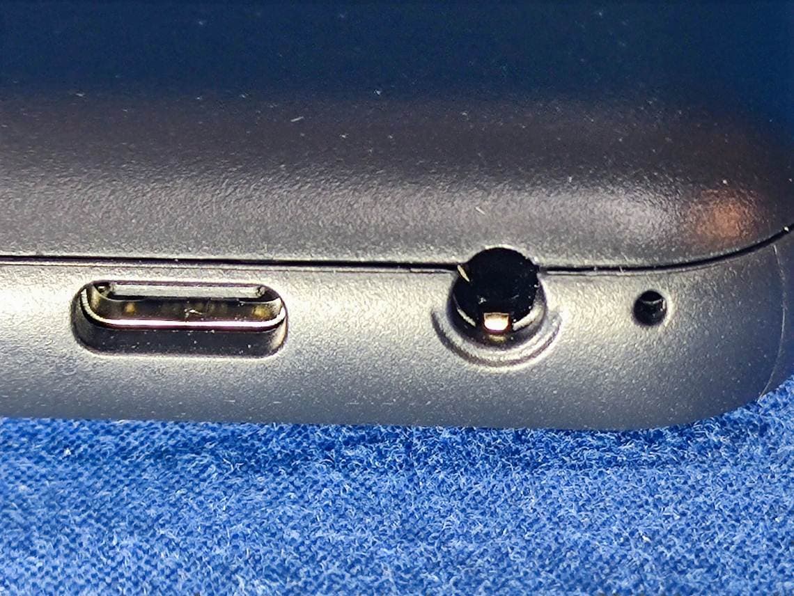
PQ4IPROK3
Jun 16, 2024Mobile Phone
Equipment Class
PCE - PCS Licensed Transmitter held to ear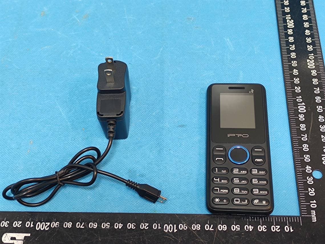
PQ4IPROK5
Jul 23, 2023Mobile Phone
Equipment Class
JBP - Part 15 Class B Computing Device Peripheral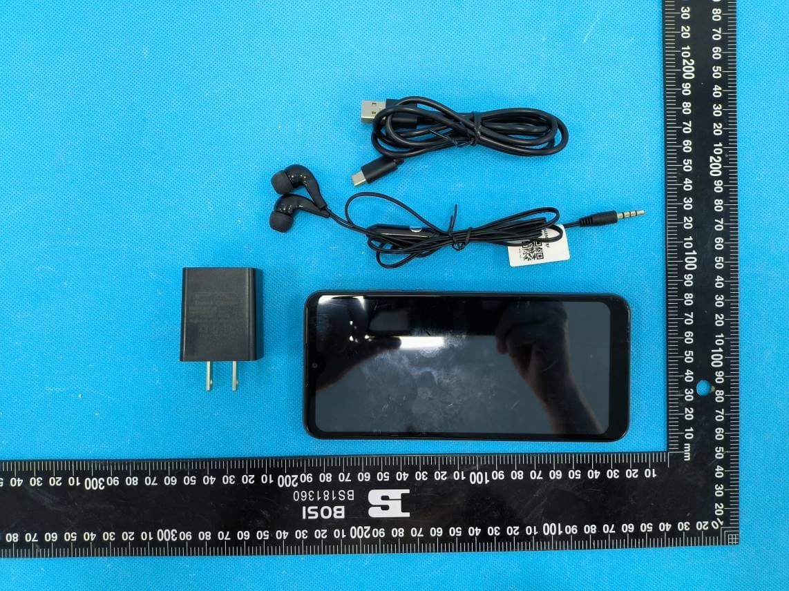
PQ4IPROS300
Nov 06, 2022Smart Phone
Equipment Class
PCE - PCS Licensed Transmitter held to ear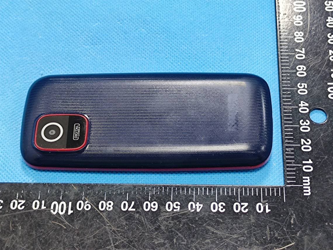
PQ4IPROA7MINI
Aug 30, 2022Mobile Phone
Equipment Class
DSS - Part 15 Spread Spectrum Transmitter