PQA-CS200B-SUBWireless Subwoofer
Jam Industries Ltd
Click to zoom
Application Details
- Equipment Class
- DSS - Part 15 Spread Spectrum Transmitter
- Date of Grant
- Nov 11, 2012
- Application Purpose
- Original Equipment
- Date of Application
- Nov 08, 2012
- Equipment Note
- Wireless Subwoofer
- Frequency Range
- 2404.00000000 - 2479.00000000
- Company
- Jam Industries Ltd
- Country
- Canada
Documents & Files
Document Text
Text extracted from the exhibit documents filed with the FCC. Open a document above to read the original.
Users Manual
Thank you for purchasing the Soundstage Sound Bar, you are about to greatly enhance your listening experience. At Soundstage we strive to create loudspeakers and loudspeaker systems engineered to deliver the best value in stereo and home theatre applications. Soundstage loudspeakers are designed for ease of use, installation, and will provide you with excellent sound quality for years to come. Reading this manual will assist you in getting acquainted with your Soundstage system. Soundstage provides a 1 year parts and service warranty on all drivers and amplifiers. To obtain servicing, please contact your Soundstage representative. The original bill of sale is required for service. VOL POWER BT CODE SRC 12 EFFECTS CS200B (1) Power Cord (1) x cordon d’alimentation (1) x CS200B Sound Bar (1) x CS200B Barre de Son (1) x Remote with batteries (1) x télécommande avec piles (1) x Rubber Bumpers (1) jeu de coussins en feutre (1) x Manual (1) x Manuel Carton Contents / Contenu de la boite Merci de vous être procuré la Barre de Son de Soundstage, vous êtes sur le point d’améliorer de façon extraordinaire votre expérience d’écoute. Chez Soundstage nous travaillons sans cesse à créer des haut-parleurs et des enceintes conçus pour offrir le meilleur rendement possible pour les utilisations en stéréophonie et pour le cinéma maison. Les enceintes Soundstage sont conçues pour être faciles à utiliser et à installer, de plus elles vous offriront une excellente qualité sonore pendant de nombreuses années. La lecture de ce mode d’emploi vous aidera à vous familiariser avec vos enceintes Soundstage. Soundstage offre une garantie d’une (1) année sur les pièces et sur le service pour tous les haut-parleurs et les amplificateurs. Pour obtenir du service sous garantie, veuillez communiquer avec votre représentant Soundstage. La facture originale de l’achat doit être présentée pour obtenir du service. CS200B Owners Manual Manuel de l’Utilisateur Powered Sound bar / Barre de son Siubwoofer / Sous-grave 1. Read Instructions - All the safety and operation instructions should be read before the sound bar is operated. 2 Reta Instructions - The safety and operating instructions should be kept for future reference. 3. Heed Warnings - All warnings on the sound bar and in these operating instructions should be followed. 4. Follow Instructions - All operating and other instructions should be followed. 5. Water and Moisture - The sound bar should not be used near water. For example, near a bathtub, washbowl, kitchen sink, laundry tub, in a wet basement or near a swimming pool. 6. Ventilation - The Sound Bar should be situated so that its location or position does not interfere with its proper ventilation. For example, the system should not be situated on a bed, sofa, rug or similar surface that may block airflow past the rear heat sinks; or placed in a built-in installation such as a bookcase or cabinet that may impede the flow of air past the heat sinks. 7. Heat - The sound bar should be situated away from heat sources such as radiators, heaters, furnace outflow vents or other devices which produce heat. 8. Power Sources - The Sound Bar should be connected to a power supply only of the type described in these operation instructions or as marked on the Component. 9. Grounding or Polarization - The sound bar is equipped with a polarized alternating-current line plug (a plug having one blade wider than the other). This plug will fit into the power outlet only one way. This is an intentional safety feature. If you are unable to insert the plug fully into the outlet, try reversing the plug. If the plug should still fail to fit, contact an electrician to replace the obsolete (unpolarized) outlet. Do not defeat the safety purpose of the polarized plug. 10. Power Cord Protection - Power supply cords should be routed so that they are not likely to be walked upon or pinched by items placed upon or against them. Pay particular attention to cords at plugs, convenience receptacles, and the point where they exit the Sound Bar. To prevent electric shock, do not use the sound bar polarized plug with an extension cord, receptacle or other outlet unless the blades can be fully inserted to prevent blade exposure. 11. Non-use Periods - The power cord of the sound bar should be unplugged from the outlet when left unused for a long period of time. 12. Damage Requiring Service - The sound bar should be serviced only by qualified service personnel when: A.Sound Bar power supply cord or the plug has been damaged; or B.Objects have fallen or liquid has spilled into the sound bar; or C. The sound bar has been exposed to rain; or D.The sound bar does not appear to operate or exhibits a marked change in performance; or E. The sound bar has been dropped or damaged. 13.Servicing - The user should not attempt to service the sound bar beyond those means described in this operating manual. All other servicing should be referred to an authorized Service Center. 14.Cleaning - Unplug the sound bar from the wall outlet before cleaning. Do not use liquid cleaners or aerosol cleaners. Use a damp cloth for cleaning. 15.Attachments - Do not use attachments not recommended as they may cause hazards. 16.Accessories - Do not place the sound bar on an unstable cart, stand, tripod, bracket, or table. The sound bar may fall, causing serious injury to a child or adult, and serious damage to the product. Use only with a cart, stand, tripod, bracket or table recommended by manufacturer, or sold with the product. Any mounting of the sound bar should follow manufacturer's instructions, and should use a mounting accessory recommended by manufacturer. An sound bar and cart combination should be moved with care. Quick stops, excessive force, and uneven surfaces may cause the product and cart combination to overturn. 17. Lightning - For added protection for the sound bar during a lightning storm, or when it is left unattended and unused for long periods of time, unplug it from t…
Text truncated - open the document above for the full version.
Cover Letter(s)
JAM INDUSTRIES LTD. FCC Confidentiality Request Number: CF303 Version: V01 Date: 01-02-2010 To the FCC and FCC TCB handling this application for certification Pursuant to 47 CFR Section 0.459(a) & (b), we, (the applicant / grantee) Company name JAM INDUSTRIES LTD. Addresss 21000 Trans Canada Highway, City Baie D’ Urfe Quebec Country Canada request non-disclosure and confidential treatment for our certification under: Grantee Code Product Number FCC ID: PQA -CS200B-SUB of the following materials submitted within this certification application: (please cross what is applicable, or add other documents) Operational Description Block Diagrams Schematics Diagrams Above materials contain secrets, proprietary and technical information, which would customarily be guarded from competitors under 47 CFR, section 0.457(d)(2). Disclosure or publication or any portion of this company confidential material to other parties could cause substantial competitive harm and provide unjustified benefits for competitors. We understand that pursuant to 47 CFR section 0.457(d)(1)(ii) disclosure of the applicant and all accompanying documentation will not be made before the date of the grant. Attestation:
Cover Letter(s)
JAM INDUSTRIES LTD. FCC Authorization Letter Number: CF304 Version: V01 Date: 01-02-2010 We, (the approval holder) Company name JAM INDUSTRIES LTD. Addresss 21000 Trans Canada Highway, City Baie D’ Urfe Quebec Country Canada declare that the following representative (agent): Name (person) Sam Lv Company name DONGGUAN EMTEK CO., LTD. Addresss No.281, Guantai Road, Nancheng District, City Dongguan Country China is hereby authorized to apply the following equipment for certification on our behalf: Product Description WIRELESS SUBWOOFER Type or Model(s) 8 inch wireless subwoofer Tradename or Brand(s) SOUNDSTAGE We also authorize Teleconformity, Mr. M. Koop, (address: Rietven 31, 7534NH Enschede, Netherlands) to process this application. Attestation:
External Photos
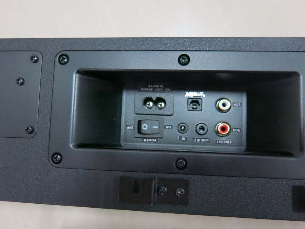
General Appearance of the EUT
ID Label/Location Info
Label Location on EUT:
Internal Photos
RF Module RF Module
RF Exposure Info
MPE evaluation FCC ID: PQA-CS200B-SUB The highest measured Peak power for each transmitter in this device: (Peak leads to worst case calculation compared to average): For FSK module (2404-2479 MHz): 0.214 mW (-6.96 dBm), with 2 dBi antenna gain The power density for each transmitter must be under the given limit . For FSK: Pradiated = Pconducted + Glinear = -6.96 dBm + 2 dBi = -4.96 dBm = 0.32 mW Power density S = (Pradiated) / (4π x d2) = 0.32 / 5026 =0.00007 mW/cm2 The calculated power density for this transmitter is far below the limit, so PASS. Remark: This device would be also generally exempted for RF exposure, because the power lies below 60/f mW. For the 2.4 G band, the limit would be 24mW, and the actual powers is 0.32 mW.
Test Report
DONGGUAN EMTEK CO., LTD. REPORT NO:KAD120817020E FCC ID: PQA-CS200B-SUB DATE: 11/01/2012 Page 1 of 44 ELECTROMAGNETIC EMISSIONS COMPLIANCE REPORT INTENTIONAL RADIATOR CERTIFICATION TO FCC PART 15 SUBPART C REQUIREMENT OF WIRELESS SUBWOOFER MODEL No.: 8 inch wireless subwoofer TRADE MARK: SOUNDSTAGE FCC ID: PQA-CS200B-SUB REPORT NO: KAD120817020E ISSUE DATE: November 01, 2012 Prepared for JAM INDUSTRIES LTD. 21000 Trans Canada Highway, Baie D’Urfe Quebec H9X 4B7 Canada Prepared by DONGGUAN EMTEK CO., LTD. No.281, Guantai Road, Nancheng District, Dongguan, Guangdong, China TEL: 86-769-22807078 FAX: 86-769-22807079 DONGGUAN EMTEK CO., LTD. REPORT NO:KAD120817020E FCC ID: PQA-CS200B-SUB DATE: 11/01/2012 Page 2 of 44 VERIFICATION OF COMPLIANCE Applicant: JAM INDUSTRIES LTD. 21000 Trans Canada Highway, Baie D’Urfe Quebec H9X 4B7 Canada Manufacturer: JAM INDUSTRIES LTD. 21000 Trans Canada Highway, Baie D’Urfe Quebec H9X 4B7 Canada Product Description: WIRELESS SUBWOOFER Trade Mark: SOUNDSTAGE Model Number: 8 inch wireless subwoofer Serial Number: N/A File Number: KAD120817020E Date of Test: August 17, 2012 to November 01, 2012 We hereby certify that: The above equipment was tested by DONGGUAN EMTEK CO., LTD. The test data, data evaluation, test procedures, and equipment configurations shown in this report were made in accordance with the procedures given in ANSI C63.4 (2009) and the energy emitted by the sample EUT tested as described in this report is in compliance with conducted and radiated emission limits of FCC Rules Part 15.247. The test results of this report relate only to the tested sample identified in this report. Approved By Sam Lv / Q.A. Manager DONGGUAN EMTEK CO., LTD. DONGGUAN EMTEK CO., LTD. REPORT NO:KAD120817020E FCC ID: PQA-CS200B-SUB DATE: 11/01/2012 Page 3 of 44 Ta b l e o f C o n t e n t s 1. GENERAL INFORMATION ................................................................................................. 5 1.1 PRODUCT DESCRIPTION........................................................................................................................... 5 1.2 RELATED SUBMITTAL(S) / GRANT (S) ..................................................................................................... 5 1.3 TEST METHODOLOGY.............................................................................................................................. 5 1.4 SPECIAL ACCESSORIES............................................................................................................................ 5 1.5 EQUIPMENT MODIFICATIONS.................................................................................................................. 5 1.6 TEST FACILITY........................................................................................................................................ 6 2. SYSTEM TEST CONFIGURATION .................................................................................... 7 2.1 EUT CONFIGURATION............................................................................................................................. 7 2.2 EUT EXERCISE........................................................................................................................................ 7 2.3 TEST PROCEDURE.................................................................................................................................... 7 2.4 LIMITATION............................................................................................................................................. 7 2.5 CONFIGURATION OF TESTED SYSTEM................................................................................................... 11 3. SUMMARY OF TEST RESULTS ....................................................................................... 12 4. DESCRIPTION OF TEST MODES .................................................................................... 13 5. CONDUCTED EMISSIONS TEST ..................................................................................... 14 5.1 MEASUREMENT PROCEDURE:................................................................................................................ 14 5.2 TEST SET-UP (BLOCK DIAGRAM OF CONFIGURATION) ....................................................................... 14 5.3 MEASUREMENT EQUIPMENT USED: ...................................................................................................... 14 5.4 MEASUREMENT RESULT:........................................................................................................................ 14 5.5 CONDUCTED MEASUREMENT PHOTOS: ................................................................................................. 17 6. RADIATED EMISSION TEST ............................................................................................ 18 6.1 MEASUREMENT PROCEDURE................................................................................................................. 18 6.2 TEST SET-UP (BLOCK DIAGRAM OF CONFIGURATION) ....................................................................... 19 6.3 MEASUREMENT EQUIPMENT USED: ...................................................................................................... 20 6.4 MEASUREMENT RESULT....................................................................................................................... 20 6.5 RADIATED MEASUREMENT PHOTOS:.................................................................................................... 26 7. CHANNEL SEPARATION TEST ....................................................................................... 27 7.1 MEASUREMENT PROCEDURE................................................................................................................. 27 7.2 TEST SET-UP (BLOCK DIAGRAM OF CONFIGURATION) ....................................................................... 27 7.3 MEASUREMENT EQUIPMENT USED: .......................…
Text truncated - open the document above for the full version.
Test Setup Photos
Setup Photos
Contact Information
Applicant
David Aggerholm
Technical Contact
Test Firm
Dongguan EMTEK Co., LtdSam Lv
Technical Specifications
| # | Rule Parts | Frequency Range | Power Output |
|---|---|---|---|
| 1 | 15C | 2.40 GHz - 2.48 GHz | 200.00 µW |
Other Applications from Jam Industries Ltd
PQA-TV3
Jul 15, 2014Active speaker
Equipment Class
DTS - Digital Transmission System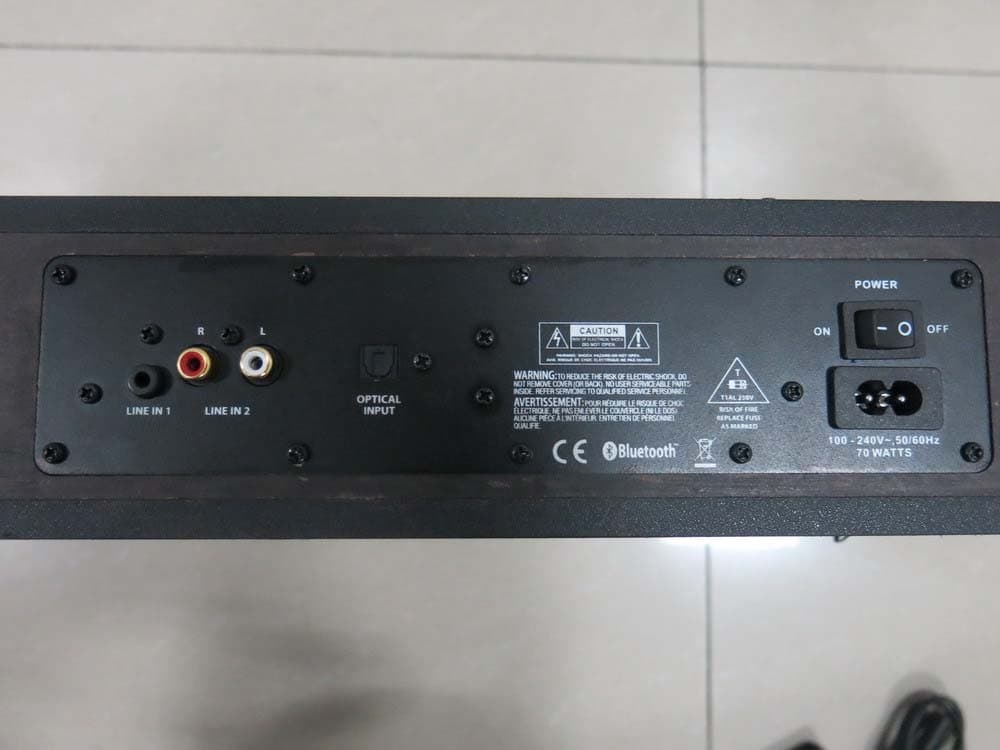
PQA-MINIV2
Jul 06, 2014Active speaker
Equipment Class
DTS - Digital Transmission System
PQA-MICROPAD
Sep 13, 2013Bluetooth Speaker
Equipment Class
DXX - Part 15 Low Power Communication Device Transmitter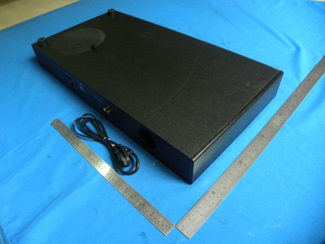
PQA-MINIPAD
Jun 09, 2013ACTIVE SPEAKER
Equipment Class
DSS - Part 15 Spread Spectrum Transmitter
PQA-WBT30
Mar 14, 2013Bluetooth Active Speaker
Equipment Class
DSS - Part 15 Spread Spectrum Transmitter