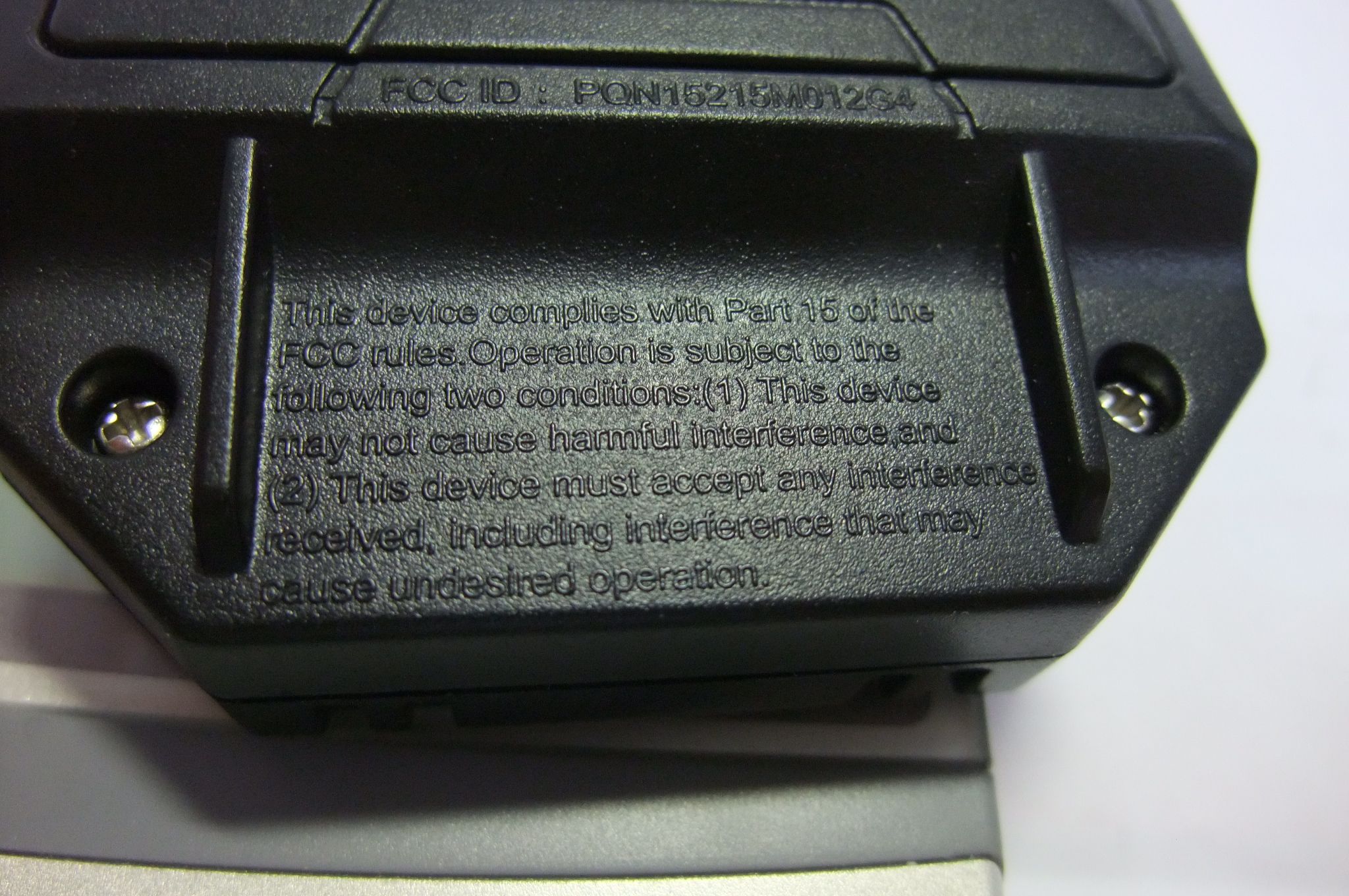
PQN15215M012G4SPG SGC Video Walkie Talkie
Spin Master Toys Far East Ltd.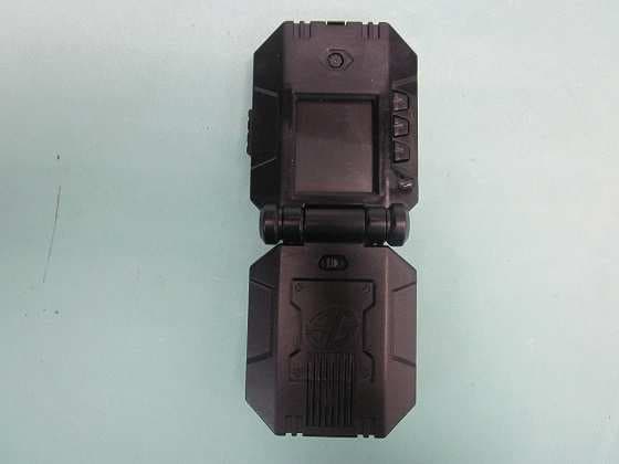
Click to zoom
Application Details
- Equipment Class
- DXX - Part 15 Low Power Communication Device Transmitter
- Date of Grant
- May 19, 2015
- Application Purpose
- Original Equipment
- Date of Application
- May 19, 2015
- Equipment Note
- SPG SGC Video Walkie Talkie
- Frequency Range
- 2405.00000000 - 2474.00000000
- Country
- Hong Kong
Documents & Files
Document Text
Text extracted from the exhibit documents filed with the FCC. Open a document above to read the original.
Users Manual
1 SPY VIDEO WALKIE TALKIEs TM CONTENTS / CONTENU : 2 VIDEO WALKIE TALKIES™, 1 USER GUIDE / MODE D’EMPLOI USER GUIDE mode d’emploi 6 + YEARS ANS ™ HOW TO OPERATE / FONCTIONNEMENT a WARNING: CHOKING HAZARD – Small parts. Not for Children under 3 years. a ATTENTION ! RISQUE D’ÉTOUFFEMENT – Contient de petits éléments. Ne convient pas aux enfants de moins de 3 ans. SCAN ME SCANNE-MOI spygear. NET VOLUME UP BUTTON AUGMENTATION DU VOLUME CAMERA APPAREIL PHOTO SPEAKER HAUT-PARLEUR TRANSMIT BUTTON BOUTON DE TRANSMISSION VOLUME DOWN BUTTON DIMINUTION DU VOLUME RANGE: UP TO 100 FT PORTÉE DE 30 M HEADPHONE JACK PRISE DES ÉCOUTEURS MODE BUTTON BOUTON DE MODE e 1. Open your VIDEO WALKIE TALKIES™ and move the power switches to the ON POSITION. 2. You will see the image from the other VIDEO WALKIE TALKIE™ in the LCD DISPLAY. 3. Press and hold the TRANSMIT BUTTON and talk into the VIDEO WALKIE TALKIE™ to transmit your voice to the other VIDEO WALKIE TALKIE™. 4. To increase or decrease the volume by the VOLUME+ and VOLUME - buttons beside the screen. NOTE: you can plug headphones into the HEADPHONE JACK to listen more stealthily. This will turn off the speaker on the VIDEO WALKIE TALKIE™. Head phone not included. Choose a headphone that complies with EN60065:2002+A12:2011. SPY FACT: If you plug headphones into both units you no longer have to press the TRANSMIT BUTTON to transmit sound to each other. Both units will continuously stream audio. f 1. Ouvrir les VIDEO WALKIE TALKIES™ et placer les interrupteurs en POSITION ON. 2. L'image venant de l'autre VIDEO WALKIE TALKIE™ s'affiche sur L'ÉCRAN LCD. 3. Maintenir le BOUTON DE TRANSMISSION enfoncé et parler pour transmettre un message à l'autre VIDEO WALKIE TALKIE™. 4. Utiliser les boutons + et - situés sur le côté de l'écran pour augmenter ou diminuer le volume. REMARQUE : Des écouteurs peuvent également être branchés dans la PRISE DES ÉCOUTEURS pour écouter en toute discrétion. Le haut-parleur sera alors désactivé. Écouteurs non fournis. Choisir des écouteurs conformes aux exigences de la norme EN60065:2002+A12:2011. ASTUCE : En branchant des écouteurs sur chaque VIDEO WALKIE TALKIE™, les espions rusés n'ont plus besoin d'appuyer sur le BOUTON DE TRANSMISSION pour communiquer. Chaque appareil diffuse le son en continu. REMARQUE : Le VIDEO WALKIE TALKIE™ s'éteint automatiquement au bout de 15 minutes d'inactivité. Un son retentit après 14 minutes d'inactivité pour indiquer l'arrêt imminent de l'appareil. Pour que le VIDEO WALKIE TALKIE™ reste allumé, appuyer sur n'importe quel bouton. VIDEO WALKIE TALKIE™ MODES / MODES DU VIDEO WALKIE TALKIE™ e 1. Press the mode button to cycle through the different modes for your VIDEO WALKIE TALKIE™ 2. Press once to switch to picture in picture mode 1 (IMG 1: You / IMG 2: Incoming signal) 3. Press once to switch to picture in picture mode 2 (IMG 1: Incoming signal / IMG 2: You) 4. SPY MODE: In spy mode your unit’s screen and speaker will turn off to make it appear off while still sending image and audio to the second unit. Your VIDEO WALKIE TALKIE™ is now a spy cam, leave it in another room to see and hear everything happening on the second unit. f 1. Appuyer sur le bouton de mode pour naviguer parmi les différents modes du VIDEO WALKIE TALKIE™. 2. Appuyer une fois pour activer le mode d'images incrustées 1 (image 1 : vous / image 2 : signal entrant). 3. Appuyer une fois pour activer le mode d'images incrustées 2 (image 1 : signal entrant / image 2 : vous). 4. MODE ESPION : En mode espion, l'écran et le haut-parleur sont éteints pour simuler l'arrêt de l'appareil, bien que celui-ci continue de transmettre des images et du son à l'autre appareil. Le VIDEO WALKIE TALKIE™ devient alors une caméra d'espion (possibilité de le laisser dans une autre pièce pour voir et entendre tout ce qu'il s'y passe depuis le deuxième appareil). NOTE: Your VIDEO WALKIE TALKIE™ will automatically turn off after 15 minutes. There will be a beeping noise at 14 minutes of inactivity to warn you about auto shut off. Press any button to keep using your VIDEO WALKIE TALKIE™. 1234 IMG 2 IMG 1 1234 IMG 1 IMG 2 ENTERING SPY MODE ICON ACTIVATION DU MODE ESPION RECIEVING SPY MODE ICON RÉCEPTION DU MODE ESPION PAIRING SEARCH ICON (appears while walkie talkies connect) DÉTECTION DU SIGNAL (apparaît pendant la synchronisation des talkies-walkies) STANDBY WARNING LIGHT (appears 1 minutes before auto shut off) VOYANT D'AVERTISSEMENT DE MISE EN VEILLE (apparaît 1 minutes avant l'arrêt automatique) VOLUME LEVEL ICON CONTRÔLE DU VOLUME ICONS LEGEND LÉGENDE DES SYMBOLES LCD SCREEN ÉCRAN LCD POWER SWITCH INTERRUPTEUR D’ALIMENTATION MICROPHONE MICRO 2 e 1. Open the battery door with a screwdriver (A). 2. If used batteries are present, remove these batteries from the unit by pulling up on one end of each battery. DO NOT remove or install batteries using sharp or metal tools. 3. Install new batteries as shown in the polarity diagram (+/-) inside the battery compartment (B). 4. Replace battery door securely (C). 5. Check your local laws and regulations for correct recycling and/or battery disposal. f 1. Ouvrir le compartiment à piles à l’aide d’un tournevis. 2. S’il contient des piles usagées, les retirer en les soulevant par l’une des extrémités. NE PAS utiliser d’objet coupant ou métallique pour retirer ou insérer des piles. 3. Insérer les nouvelles piles en respectant le schéma de polarité (+/-) dans le compartiment des piles. 4. Bien refermer le compartiment des piles. 5. Recycler ou jeter les piles usagées conformément à la législation locale. HOW TO INSTALL BATTERIES INSTALLATION DES PILES eNOTE: If normal function of the product is disturbed or interrupted, strong electro- magnetic interference may be causing the issue. To reset product, turn it completely off, then turn it back on. If normal operation does not resume, move the product to another location and try again. To ensure normal performance, change the batteries, as low batteries may not allow full func…
Text truncated - open the document above for the full version.
External Photos
PHOTOGRAPH OF THE PRODUCT FRONT VIEW OF THE PRODUCT REAR VIEW OF THE PRODUCT PHOTOGRAPH OF THE PRODUCT LEFT VIEW OF THE PRODUCT RIGHT VIEW OF THE PRODUCT TOP VIEW OF THE PRODUCT BTTOM VIEW OF THE PRODUCT
Internal Photos
PHOTOGRAPH OF THE PRODUCT INNER CIRCUIT TOP VIEW PHOTOGRAPH OF THE PRODUCT INNER CIRCUIT BOTTOM VIEW PHOTOGRAPH OF THE PRODUCT PHOTOGRAPH OF THE PRODUCT
Test Report
STC Test Report Date: 2015-04-15 Page 1 of 30 No.: DM119016 Applicant: Spin Master Toys Far East Ltd. Room 1113, 11/F., Chinachem Golden Plaza, 77 Mody Road, Tsim Sha Tsui East, Kowloon, Hong Kong Manufacturer: Spin Master Toys Far East Ltd. Room 1113, 11/F., Chinachem Golden Plaza, 77 Mody Road, Tsim Sha Tsui East, Kowloon, Hong Kong Description of Sample(s): Submitted sample(s) said to be Product: SPG SGC Video Walkie Talkies Brand Name: N/A Model Number: 15215 FCC ID: PQN15215M012G4 Date Sample(s) Received: 2015-04-03 Date Tested: 2015-04-04 Investigation Requested: Perform ElectroMagnetic Interference measurement in accordance with FCC 47CFR [Codes of Federal Regulations] Part 15: 2014 and ANSI C63.4: 2009 for FCC Certification. Conclusion(s): The submitted product COMPLIED with the requirements of Federal Communications Commission [FCC] Rules and Regulations Part 15. The tests were performed in accordance with the standards described above and on Section 2.2 in this Test Report. Remark(s): --- LONG Yun Jian, Along Authorized Signatory ElectroMagnetic Compatibility Department For and on behalf of STC (Dongguan) Company Limited STC Test Report Date: 2015-04-15 Page 2 of 30 No.: DM119016 CONTENT: Cover Page 1 of 30 Content Page 2 of 30 1.0 General Details 1.1 Equipment Under Test [EUT] Page 3 of 30 1.2 Description of EUT Operation Page 3 of 30 1.3 Date of Order Page 3 of 30 1.4 Submitted Sample Page 3 of 30 1.5 Test Duration Page 3 of 30 1.6 Country of Origin Page 3 of 30 2.0 Technical Details 2.1 Investigations Requested Page 4 of 30 2.2 Test Standards and Results Summary Page 4 of 30 3.0 Test Results 3.1 Emission Page 5-18 of 30 3.2 Bandwidth Measurement Page 19-25 of 30 Appendix A List of Measurement Equipment Page 26 of 30 Appendix B Photographs Page 27-30 of 30 STC Test Report Date: 2015-04-15 Page 3 of 30 No.: DM119016 1.0 General Details 1.1 Equipment Under Test [EUT] Description of Sample(s) Product: SPG SGC Video Walkie Talkies Manufacturer: Spin Master Toys Far East Ltd. Brand Name: N/A Model Number: 15215 Rating: 4.5Vd.c. (“AA” size battery x 3) 1.2 Description of EUT Operation The Equipment Under Test (EUT) is a Video Walkie Talkies of Spin Master Toys Far East Ltd. The transceiver operating in the 2.4GHz ISM frequency band. The RF signal was modulated by IC, the type of modulation used is GFSK. 1.3 Date of Order 2015-04-03 1.4 Submitted Sample(s): 1 Sample 1.5 Test Duration 2015-04-04 1.6 Country of Origin China STC Test Report Date: 2015-04-15 Page 4 of 30 No.: DM119016 2.0 Technical Details 2.1 Investigations Requested Perform Electromagnetic Interference measurements in accordance with FCC 47CFR [Codes of Federal Regulations] Part 15: 2014 Regulations and ANSI C63.4:2009 for FCC Certification. 2.2 Test Standards and Results Summary Tables EMISSION Results Summary Test Condition Test Requirement Test Method Class / Test Result Severity Pass Fail N/A Field Strength of Fundamental & Harmonics Emissions FCC 47CFR 15.249 ANSI C63.4:2009 N/A Radiated Emissions FCC 47CFR 15.209 ANSI C63.4:2009 N/A AC Mains Conducted Emissions FCC 47CFR 15.207 ANSI C63.4:2009 N/A Note: N/A - Not Applicable STC Test Report Date: 2015-04-15 Page 5 of 30 No.: DM119016 3.0 Test Results 3.1 Emission 3.1.1 Radiated Emissions Test Requirement: FCC 47CFR 15.249 & FCC 47CFR 15.209 Test Method: ANSI C63.4:2009 Test Date: 2015-04-04 Mode of Operation: Communication mode Test Method: The sample was placed 0.8m above the ground plane of semi-anechoic Chamber*. Measurements in both horizontal and vertical polarities were performed. During the test, each emission was maximized by: having the EUT continuously working, investigated all operating modes, considered typical configuration to obtain worst position, manipulating interconnecting cables, rotating turntable, varying antenna height from 1m to 4m in both horizontal and vertical polarizations. The emissions worst-case are shown in Test Results of the following pages. *: Semi-anechoic chamber located on the STC (Dongguan) Company Ltd. 68 Fumin Nan Road, Dalang, Dongguan, Guangdong, PRC with a metal ground plane filed with the FCC pursuant to section 2.948 of the FCC rules, with Registration Number: 629686. STC Test Report Date: 2015-04-15 Page 6 of 30 No.: DM119016 Absorbers Spectrum Analyzer Setting: 9KHz – 30MHz (Pk & Av) RBW: 10kHz VBW: 30kHz Sweep: Auto Span: Fully capture the emissions being measured Trace: Max. hold 30MHz – 1GHz (QP) RBW: 120kHz VBW: 120kHz Sweep: Auto Span: Fully capture the emissions being measured Trace: Max. hold Above 1GHz (Pk & Av) RBW: 3MHz VBW: 3MHz Sweep: Auto Span: Fully capture the emissions being measured Trace: Max. hold Test Setup: Measurement Receiver Computer Ground Plane - Absorbers placed on top of the ground plane are for measurements above 1000MHz only. - Measurements between 30MHz to 1000MHz made with Bi-log antennas, above 1000MHz horn antennas are used, 9kHz to 30MHz loop antennas are used. Turn-table Distance = 3m Semi-Anechoic Chamber EUT STC Test Report Date: 2015-04-15 Page 7 of 30 No.: DM119016 Limits for Field Strength of Fundamental & Harmonics Emissions [FCC 47CFR 15.249]: Frequency Range of Fundamental Field Strength of Fundamental Emission Field Strength of Harmonics Emission [MHz] [microvolts/meter] [microvolts/meter] 902-928 500,000 [Quasi-Peak] 500 [Average] 2400-2483.5 50,000 [Average] 500 [Average] Results of Tx mode (Lowest Frequency Channel-2405 MHz): Pass CorrectionLimit @3mE-Field FactorPolarity 2405.0066.336.8103.1142,889.4500,000Vertical 2405.0065.036.4101.4117,489.8500,000Horizontal Field Strength of Fundamental Emissions Peak Value FrequencyMeasured Level @3m Field Strength MHz Field Strength CorrectionLimit @3mE-Field FactorPolarity 2405.0054.236.891.035,481.350,000Vertical 2405.0052.636.489.028,183.850,000Horizontal MHz Field Strength Field Strength of Fundamental Emissions Average Value FrequencyMeasured Level @3m Field Strength CorrectionLimit @3mE-Field FactorPolarity 4810.014.441.555…
Text truncated - open the document above for the full version.
Contact Information
Applicant
Tommy So(Senior Quality Manager)
Test Firm
The Hong Kong Standards and Testing Centre Ltd.Wilson Wong
Technical Specifications
| # | Rule Parts | Frequency Range | Power Output |
|---|---|---|---|
| 1 | 15C | 2.40 GHz - 2.47 GHz | - |
Other Applications from Spin Master Toys Far East Ltd.
PQN66807TX2G4R1
Jul 03, 2024MJC RDC Megalodon Storm GEN 1pk SLD(MCU ABE2402X1)
Equipment Class
DXX - Part 15 Low Power Communication Device TransmitterPQN66807RX2G4R1
Jul 03, 2024MJC RDC Megalodon Storm GEN 1pk SLD(MCU ABE2402X1)
Equipment Class
DXX - Part 15 Low Power Communication Device Transmitter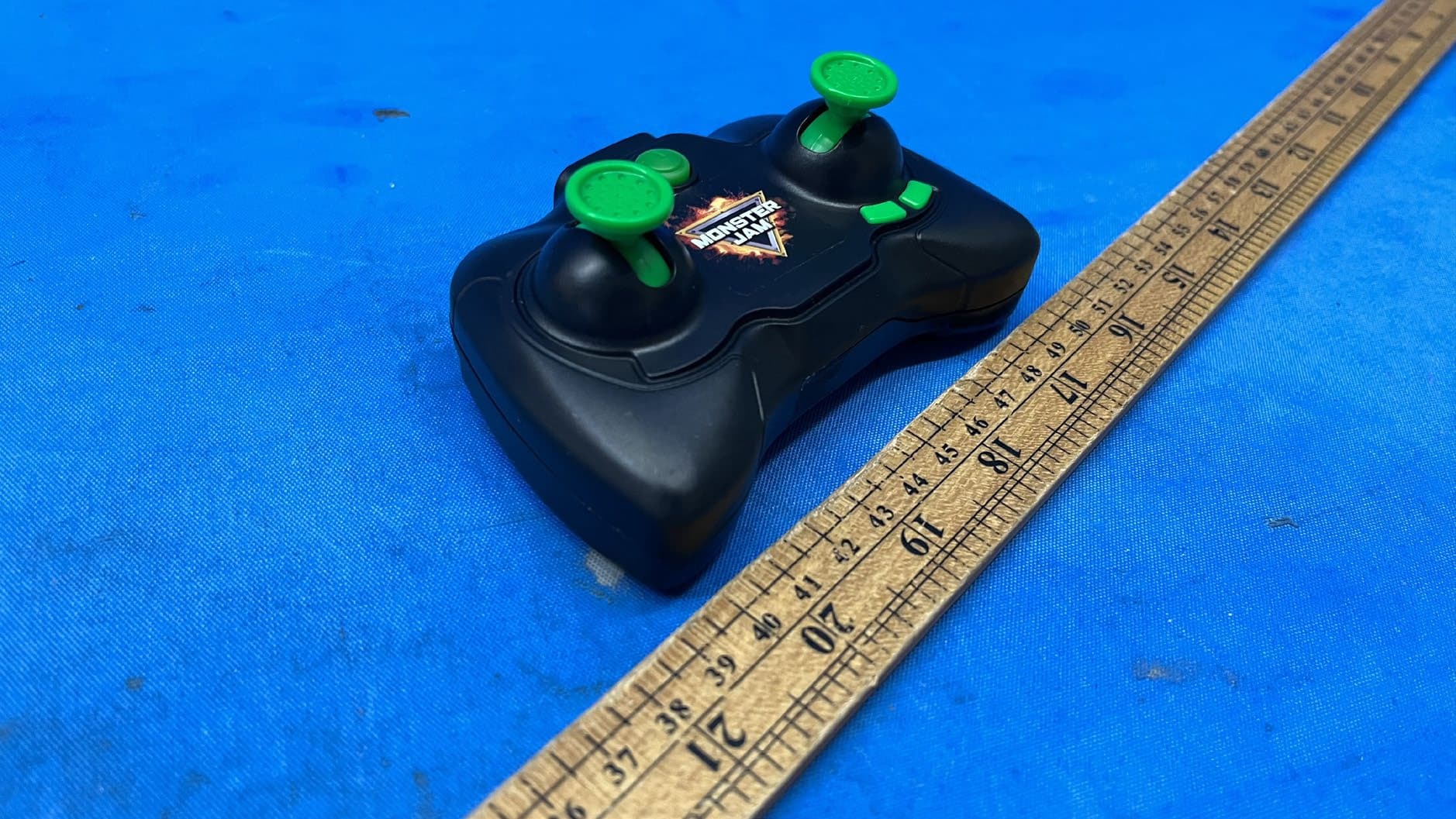
PQN66804TX2G43
Apr 03, 2024MJC Mega Grave Digger, MJC RDC Mega Grave Digger, MJC RDC Mega El Toro Loco, MNJ RDC Mega Megalodon RC, TRGT MIXED MEGA MJ HAFT PALLET, MJC COP Mega RC Asst PAL
Equipment Class
DXX - Part 15 Low Power Communication Device Transmitter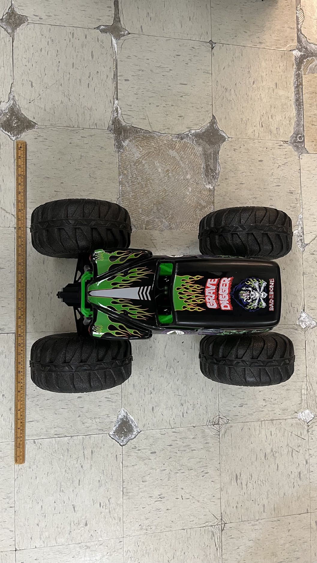
PQN66804RX2G43
Apr 03, 2024MJC Mega Grave Digger, MJC RDC Mega Grave Digger, MJC RDC Mega El Toro Loco, MNJ RDC Mega Megalodon RC, TRGT MIXED MEGA MJ HAFT PALLET, MJC COP Mega RC Asst PAL
Equipment Class
DXX - Part 15 Low Power Communication Device TransmitterPQN68126TX2G4
Aug 29, 2023HEX RDC HxmdPrSrEltStnrCrct EN GML2pkSLD
Equipment Class
DXX - Part 15 Low Power Communication Device Transmitter