PQN44354TX27145F14 Tomcat
Spin Master Toys Far East Ltd.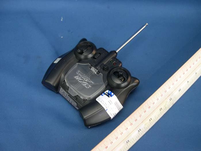
Click to zoom
Application Details
- Equipment Class
- DXX - Part 15 Low Power Communication Device Transmitter
- Date of Grant
- Sep 20, 2010
- Application Purpose
- Original Equipment
- Date of Application
- Sep 20, 2010
- Equipment Note
- F14 Tomcat
- Frequency Range
- 27.14500000 - 27.14500000
- Country
- Hong Kong
Documents & Files
Document Text
Text extracted from the exhibit documents filed with the FCC. Open a document above to read the original.
Users Manual
® INSTRUCTION GUIDE The Air Hogs ® F-14 Tomcat ® is a revolutionary radio controlled jet that is a true backyard flyer. You can hand toss or take off from the ground using the landing gear. The F-14 Tomcat ® uses digital proportional control which provides hobby like flight performance. Controller/Charger Antenna ON/OFF/CHARGE Switch Throttle Charge Door (to access Charge Nozzle) Charge LED Power LED Left/Right Toggle Steering Trim Knob Main Wing Propeller F-14 Tomcat ® Vertical Tail Wings Propeller Fuselage Wheels Main Wing Nose Wheel Fuselage 1 1.Open the battery door with a screwdriver. 2.If used batteries are present, remove these batteries from the unit by pulling up on one end of each battery. 3.Install new batteries as shown in the polarity diagram (+/-) inside the battery compartment. 4.Replace battery door securely. 5.Check your local laws and regulations for correct recycling and/or battery disposal. Controller/Charger Battery Compartment Door 6 x AA 1.5-V Alkaline Batteries IMPORTANT TIP: TURN YOUR CONTROLLER ON TO ENSURE THAT THE BATTERIES ARE INSTALLED PROPERLY. THE RED LED LIGHT ON THE FRONT OF THE CONTROLLER SHOULD TURN RED. After each flight, store the jet in the package to prevent damage. REPAIRS CONTROLLER/CHARGER BATTERY INSTALLATION If the wings on your jet get damaged they can be easily repaired with clear tape as shown. ADDING WHEELS TO THE F-14 TOMCAT ® Repair Attach the front and rear wheels to the jet as shown. The wires on the wheels slide into the slots on the jet and clip into place. Battery Compartment Your F-14 Tomcat ® jet has a preinstalled rechargeable battery in the jet’s fuselage. Because the Controller’s AA batteries are used for 2 functions – charging and controlling, they will need to be replaced every so often. Antenna rePLICA SERIES Contents: 1 x Air Hogs ® F-14 Tomcat ® 1 x Remote Control/Charger, 1 x User Instruction Guide 1 x Landing Gear, 1 X Spare Props PRE-FLIGHT ENVIRONMENT CHECK CHARGING YOUR F-14 TOMCAT ® Set the controller/ charger switch to CHARGE. 4.Carefully push the charge nozzle all the way into the jet’s charge port located on the bottom of the jet. FLYING INSTRUCTIONS Fully extend controller/charger antenna. Push the controller/ charger switch to ON. Power light will turn RED. 1 2 3 5 5.During the charging process, the green charge light will turn ON. When the jet is completely charged, the green charging light will turn OFF. 6. Remove charge nozzle gently from the jet’s charge port. Store charge nozzle and close the charge door. 5 Important Charging Information: • Before taking your initial flight, charge the jet for a complete charge cycle on your charger. • Depending upon the length of future play, you will not need to complete a full charge before each flight. NOTE:A shortened charge results in a shorter playtime (may take up to 30-40 minutes to fully charge). Green Charge Light 1. Location – Fly in a large wide open, grassy location that is free of buildings, trees, overhead wires, and other obstructions.Do not fly near people or animals. 2. Weather –Fly on mild, sunny days. Do not fly in electrical storms, rain, sleet, snow or other adverse weather conditions. Do not fly if the temperature is below 7°C/45°F. In very cold temperatures, the jet will become fragile and the engine performance will decrease. 3. Wind Conditions –Do not fly in strong winds. Strong winds may overpower the aircraft and make it difficult to control. 5 NOTE: We recommend that you start flying by hand launching to get used to the controls. When preparing for take-off, check the direction of the wind. Always launch the jet against the wind for best take-off and flight results. Use your left hand to apply at least half throttle on the controller/charger. Gently toss the jet forward into the wind and parallel to the ground. Refrain from using the directional toggle while launching the jet. 1.Push the ON/OFF switch on the bottom of the jet to the LEFTto turn the jet OFF. 2. Set the controller/charger switch to OFF. 3.Flip the charge door open to reveal the charge nozzle. 6 If you are taking off from the ground, make sure you are on a smooth paved surface, and put the throttle all the way forward for fast acceleration. 4 Push the jet’s ON/OFF switch to the right to turn the jet to ON. 2 4 CONTROLLING JET FLIGHT Turn the controller/ charger OFF by pulling the switch down. LEFT TURN Move the direction toggle to the left. If you want to straighten out your flight path, turn the Steering Trim Knobto the left or right during flight. FLIGHT ADJUSTMENTS ONCE THE JET HAS LANDED Steering Trim Knob Controller/Charger 2 1 To ACCELERATE or climb Push the throttle (left toggle) forward. RIGHT TURN Move the direction toggle to the right. Controller/Charger TO LAND Select a soft grassy area and pull the throttle (left toggle) back slowly and then release. For example: To make the jet move to the LEFT, move the toggle to the RIGHT. CONTROL REVERSAL IMPORTANT: When the jet is flying towards you, the controls are reversed. Turn jet OFFby pushing switch to the left. 3 IMPORTANT BATTERY INFORMATION • Requires 6 x 1.5-V AA alkaline batteries (not included). • Batteries are small objects. • Replacement of batteries must be done by adults. • Follow the polarity (+/-) diagram in the battery compartment. • Promptly remove dead batteries from the toy. • Dispose of used batteries properly. • Remove batteries for prolonged storage. • DO NOT incinerate used batteries. • DO NOT dispose of batteries in fire, as batteries may explode or leak. • DO NOT mix old and new batteries or types of batteries (i.e. alkaline/standard). • DO NOT use rechargeable batteries. • DO NOT recharge non-rechargeable batteries. • DO NOT short-circuit the supply terminals. Your F-14 Tomcat ® is equipped with a Lithium Polymer battery. SPECIAL LiPO BATTERY INSTRUCTIONS: • Never charge battery unattended. • Charge battery in isolated area. Keep away from flammable materials. • Do not expose to direct sunlight. • The…
Text truncated - open the document above for the full version.
Block Diagram
11 22 33 44 55 66 D D C C B B A A ANT Regulator Low pass Filter RF AMP Q 2 and Oscillator Y 1 ,Q 1 27.145MHZ Charging Circuit A1 A2 A3 A4 B1 B2 B3 B4 SW1 F14 27MHz TX Block Diagram 27.145MHZ EM78P259 U 1 LDO 5.0V L4 .C 9 .C 10 Modulator EncoderU 2 Key controlL. R. VR1. VR 2 6*AA 9.0V Revision Sheet of Size Date:Date:Date: Drawing By:Checked By:Approved By: Title: Spin Master DongGuan Technical Consultancy Servicing Co. Ltd Model NO. V 0 1 A 4 1 1 A ug . 9. 2010 F14 27MHz TX Block Diagram 4437 9 Jonye
External Photos
INTERTEK TESTING SERVICE Report No.: HK10080845-1 Equipment Photographs Model : 44354 (External) FCC ID: PQN44354TX27145 INTERTEK TESTING SERVICE Report No.: HK10080845-1 Equipment Photographs Model : 44354 (External) FCC ID: PQN44354TX27145
ID Label/Location Info
27MHz TX FCC ID:PQN44354TX27145 This device complies with Part 15 of the FCC Rules. FCC ID:PQN44354TX27145 This device complies with Part 15 of the FCC Rules. Operation is subject to the following two conditions: (1) this device may not cause harmful interference, and (2) this device must accept any interference received, including interference that may cause undesired operation. 50mmX15mm
Internal Photos
INTERTEK TESTING SERVICE Report No.: HK10080845-1 Equipment Photographs Model : 44354 (Internal) FCC ID: PQN44354TX27145 INTERTEK TESTING SERVICE Report No.: HK10080845-1 Equipment Photographs Model : 44354 (Internal) FCC ID: PQN44354TX27145 INTERTEK TESTING SERVICE Report No.: HK10080845-1 Equipment Photographs Model : 44354 (Internal) FCC ID: PQN44354TX27145
Operational Description
FCC ID: PQN44354TX27145 The brief circuit description is listed as follows: - Q2 and associated circuit act as Modulator and Amplifier. - Q1, Y1 and associated circuit act as 27.145 MHz Oscillator. - U2 acts as Encoder and MCU. - U1 and associated circuit act as Voltage Regulator for U2. - SW1 acts as On/ Off Switch. - SW2 – SW3 act as Control Keys. - Q3, Q4, Q6 and associated circuit act as Charger Circuit. Antenna Used : Telescope-type antenna with unique antenna connector.
Schematics
11 22 33 44 D D C C B B A A Revision Sheet of Size Date:Date:Date: Drawing By:Checked By:Approved By: Title: Spin Master DongGuan Technical Consultancy Servicing Co. Ltd Model NO. V0 1 A4 1 1 A ug . 9 .2010 P52 1 P53 2 P54 3 RESET 4 VSS 5 P60 6 P61 7 P62 8 P63 9 P64 10 P65 11 P66 12 P67 13 VDD 14 P70 15 P55 16 P50 17 P51 18 P57 19 P56 20 U2 EM78P259 DICE 10ohm R6 SW2 LEFT SW3 RIGHT 1M R9 1M R10 560 R12 22K R8 104 C12 LED2GREEN P52 P53 P54 P55 P50 P51 P65 P66 104 C15 VDD 0.02uF C6 47pF C7 150pF C9 150pF C10 Q1C945 Q2PH2369 LED1RED 7.5T L4 2.2uH L2 5.6uH L1 ANT1 BAT+ 27.145MHz 1 2 0pF C13 68pF C8 56pF C11 220ohm R13 3.3uH L3 1 2 Y1 27.145MHZ 91K R11 203pF C14 470 R7 P55 P60 P64 BT1 AA x 6 IN 1 GND 2 OUT 3 U1 PE9S20 5.0V SW1 390K R4 300K R5 104 C3 104 C5 104 C4 100uF C2 P50 VDD BAT+ P66 ONOFFCHARGE D1 1N4148 10R R3 VDD 47K R2 2R2 R1 220uF C1 J1 P60 J2 P64 1M R27 1M R26 VDD BAT+ P65 1 2 JP1 P51 Charge Port 1K R25 1K R17 104 C18 Q4UTC 2SB772 TO126 1R/ 1W R15 Q6LRC 8550D 2 R7 1W R14 120R R23 100K R21 Q3LRC 8050D 1K R24 D21N4001 100K 1% R16 100K 1% R189.1 K 1% R22 5K VR1 5K VR2 104 C17 104 C16 P52 P53 Trottle Steering Trim VDD Q5 LRC MMBT3906 1K R20 100K R19 P54 F14 TX Unit 8.2K R28 J1 ID 1 0 ID1ID2 FUSE11.5A Jonye 44354
Test Report
INTERTEK TESTING SERVICES Report No.: HK10080845-1 Sample No.: 1/1 Code: FCC15C_c / Effective Date: 04 Aug 2009 ( of ) Bandwidth / Bandedge Plot – Pursuant to FCC Part 15 Section 15. 227 Requirement (Pass) INTERTEK TESTING SERVICES Report No.: HK10080845-1 Sample No.: 1/1 Code: FCC15C_c / Effective Date: 04 Aug 2009 ( of ) Bandwidth / Bandedge Plot – Pursuant to FCC Part 15 Section 15. 227 Requirement (Pass) Duty Cycle: = 5 x 0.5 + 2 + 10 x 1.4 + 7 x 0.6 ms 100 = 22.7 ms 100 = 0.227 Average Factor = 20log(0.227) = -12.8 dB INTERTEK TESTING SERVICES Report No.: HK10080845-1 Sample No.: 1/1 Code: FCC15C_c / Effective Date: 04 Aug 2009 ( of ) Bandwidth / Bandedge Plot – Pursuant to FCC Part 15 Section 15. 227 Requirement (Pass) INTERTEK TESTING SERVICES Report No.: HK10080845-1 Sample No.: 1/1 Code: FCC15C_c / Effective Date: 04 Aug 2009 ( of ) Bandwidth / Bandedge Plot – Pursuant to FCC Part 15 Section 15. 227 Requirement (Pass)
Test Report
INTERTEK TESTING SERVICES Report No.: HK10080845-1 Sample No.: 1/1 Code: FCC15C_c / Effective Date: 04 Aug 2009 ( of ) Bandwidth / Bandedge Plot – Pursuant to FCC Part 15 Section 15. 227 Requirement
Test Report
- The test report only allows to be revised within the retention period unless further standard or the requirement was noticed. - This report is for the exclusive use of Intertek's Client and is provided pursuant to the agreement between Intertek and its Client. Intertek's responsibility and liability are limited to the terms and conditions of the agreement. Intertek assumes no liability to any party, other than to the Client in accordance with the agreement, for any loss, expense or damage occasioned by the use of this report. Only the Client is authorized to permit copying or distribution of this report and then only in its entirety. Any use of the Intertek name or one of its marks for the sale or advertisement of the tested material, product or service must first be approved in writing by Intertek. The observations and test results in this report are relevant only to the sample tested. This report by itself does not imply that the material, product, or service is or has ever been under an Intertek certification program. Intertek Testing Services Hong Kong Ltd. 2/F., Garment Centre, 576 Castle Peak Road, Kowloon, Hong Kong. Tel: (852) 2173 8888 Fax: (852) 2785 5487 Website: www.hk.intertek-etlsemko.com TEST REPORT Report No.: HK10080845-1 Spin Master Toys Far East Limited Application For Certification (Original Grant) (FCC ID: PQN44354TX27145) Transmitter Prepared and Checked by: Approved by: Signed On File Benny Lau Engineer Chan Chi Hung, Terry Senior Lead Engineer Date: September 14, 2010 INTERTEK TESTING SERVICES Report No.: HK10080845-1 FCC ID: PQN44354TX27145 i GENERAL INFORMATION Spin Master Toys Far East Limited MODEL: 44354 FCC ID: PQN44354TX27145 Grantee: Spin Master Toys Far East Limited Grantee Address: Room 1113, 11/F., Chinachem Golden Plaza, 77 Mody Road, Tsim Sha Tsui East, Kowloon, Hong Kong. Contact Person: Andy Wong Tel: (86) 0769-81080068 Fax: (86) 0769-82207100 e-mail: [email protected] Manufacturer: N/A Manufacturer Address: N/A Brand Name: N/A Model: 44354 Additiional Models: 1012095, 6010469, 1013491, 6012633, 1013185 Type of EUT: Transmitter Description of EUT: F14 Tomcat Serial Number: N/A FCC ID: PQN44354TX27145 Date of Sample Submitted: August 18, 2010 Date of Test: August 25, 2010 Report No.: HK10080845-1 Report Date: September 14, 2010 Environmental Conidtions: Temperature: +10 to 40°C Humidity: 10 to 90% INTERTEK TESTING SERVICES Report No.: HK10080845-1 FCC ID: PQN44354TX27145 ii SUMMARY OF TEST RESULT Spin Master Toys Far East Limited MODEL: 44354 FCC ID: PQN44354TX27145 TEST SPECIFICATION REFERENCE RESULTS Maximum Peak Output Power 15.247(b), (c) / RSS-210 A8.4 N/A Hopping Channel Carrier Frequencies Separation (for 2.4GHz Digital) 15.247(e) / RSS-210 A8.1 N/A 20dB Bandwidth of the Hopping Channel 15.247(a) / RSS-210 A8.1 N/A Number of Hopping Frequencies 15.247(e) / RSS-210 A8.1 N/A Average Time of Occupancy of Hopping Frequency 15.247(e) / RSS-210 A8.1 N/A Anteann Conducted Spurious Emissions 15.247(d) / RSS-210 A8.5 N/A Radiated Spurious Emissions 15.247(d) / RSS-210 A8.5 N/A RF Exposure Compliance 15.247(i) / RSS-Gen 5.5 N/A Transmitter Power Line Conducted Emissions 15.207 / RSS-Gen 7.2.2 N/A Transmitter Field Strength (for 27MHz) 15.227 / RSS-310 3.8 Pass Transmitter Field Strength (for 40MHz) 15.229 / RSS-210 A2.7 N/A Transmitter Field Strength, Bandwidth and Timing Requirement (for Remote Control) 15.231(a) / RSS-210 A1.1.1 N/A Transmitter Field Strength, Bandwidth and Timing Requirement (for 433MHz) 15.231(e) / RSS-210 A1.1.5 N/A Transmitter Field Strength and Bandwidth Requirement(for 88-108MHz) 15.239 / RSS-210 A2.8 N/A Transmitter Field Strength and Bandwidth Requirement(for 902- 928MHz or 2.4GHz) 15.249 / RSS-210 A2.9 N/A Transmitter Field Strength and Bandwidth Requirement (for 49MHz) 15.235 / RSS-310 3.9 N/A Receiver / Digital Device Radiated Eissions 15.109 / ICES-003 N/A Digital Device Conducted Emissions 15.107 / ICES-003 N/A Note: 1. The EUT uses a Telescope-type antenna (with unique antenna connector) which, in accordance to section 15.203, is considered sufficient to comply with the pervisions of this section. 2. Pursuant to FCC part 15 Section 15.215(c), the 20 dB bandwidth of the emission was contained within the frequency band designated (mentioned as above) which the EUT operated. The effects, if any, from frequency sweeping, frequency hopping, other modulation techniques and frequency stability over excepted variations in temperature and supply voltage were considered. INTERTEK TESTING SERVICES Report No.: HK10080845-1 FCC ID: PQN44354TX27145 iii Table of Contents 1.0 General Description....................................................................................... 1 1.1 Product Description .......................................................................................... 1 1.2 Related Submittal(s) Grants.............................................................................. 1 1.3 Test Methodology............................................................................................. 1 1.4 Test Facility ...................................................................................................... 1 2.0 System Test Configuration ............................................................................ 2 2.1 Justification ...................................................................................................... 2 2.2 EUT Exercising Software.................................................................................. 2 2.3 Special Accessories ......................................................................................... 2 2.4 Equipment Modification .................................................................................... 2 2.5 Measurement Uncertainty................................................................................. 2 2.6 Support Equipment List and Description ........................................................... 3 3.0 Emission Re…
Text truncated - open the document above for the full version.
Test Setup Photos
INTERTEK TESTING SERVICE Report No: HK10080845-1 Configuration Photographs Worst-Case Radiated Emissions (Front View) Model : 44354 5 Figure 1 FCC ID: PQN44354TX27145 INTERTEK TESTING SERVICE Report No: HK10080845-1 Configuration Photographs Worst-Case Radiated Emissions (Back View) Model : 44354 5 Figure 2 FCC ID: PQN44354TX27145
Contact Information
Applicant
Tommy So(Senior Quality Manager)
Technical Contact
Intertek Testing Services Hong Kong LtdBen Ho
[email protected]852-21738505
2/F Garment Centre · Kowloon · Hong Kong
Non-Technical Contact
Intertek Testing Services Hong Kong LtdBen Ho
[email protected]852-21738505
Test Firm
Intertek Testing Services Hong Kong Ltd.Billy Chow
Technical Specifications
| # | Rule Parts | Frequency Range | Power Output |
|---|---|---|---|
| 1 | 15C | 27.145 MHz - 27.145 MHz | - |
Other Applications from Spin Master Toys Far East Ltd.
PQN66807TX2G4R1
Jul 03, 2024MJC RDC Megalodon Storm GEN 1pk SLD(MCU ABE2402X1)
Equipment Class
DXX - Part 15 Low Power Communication Device TransmitterPQN66807RX2G4R1
Jul 03, 2024MJC RDC Megalodon Storm GEN 1pk SLD(MCU ABE2402X1)
Equipment Class
DXX - Part 15 Low Power Communication Device Transmitter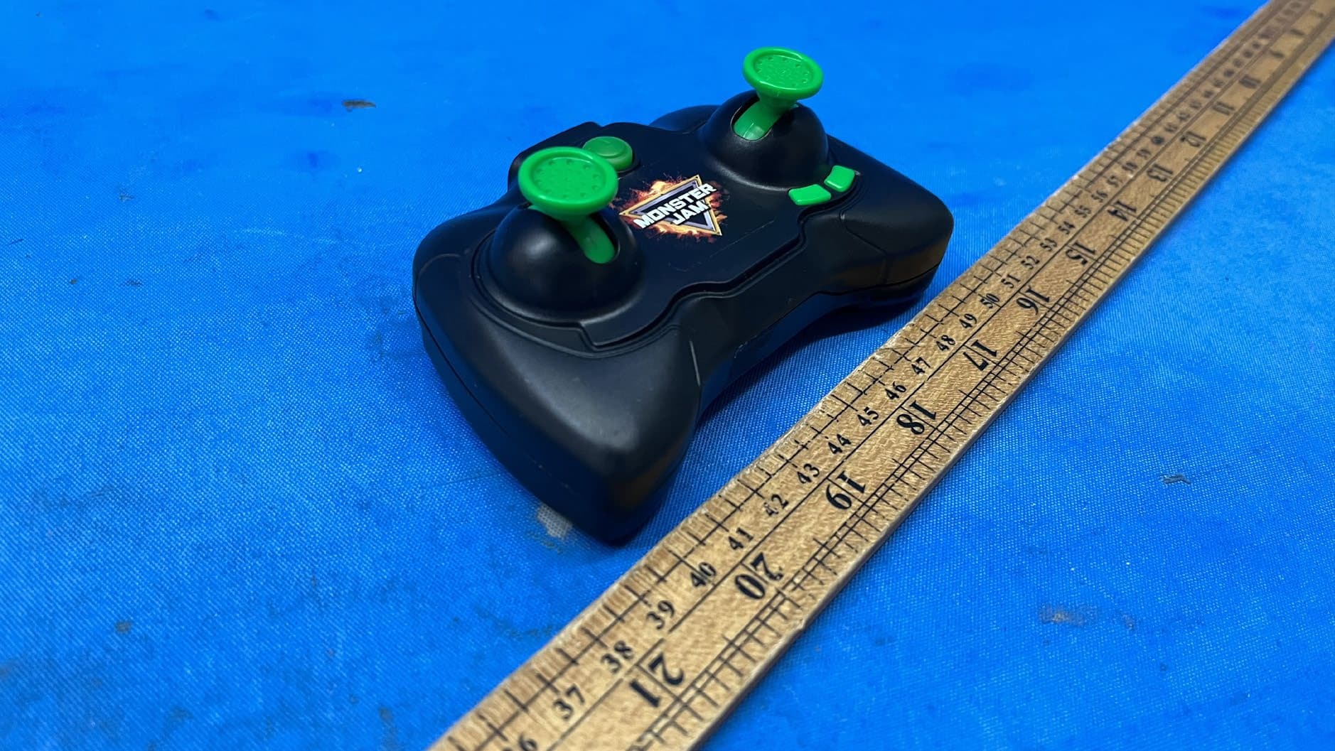
PQN66804TX2G43
Apr 03, 2024MJC Mega Grave Digger, MJC RDC Mega Grave Digger, MJC RDC Mega El Toro Loco, MNJ RDC Mega Megalodon RC, TRGT MIXED MEGA MJ HAFT PALLET, MJC COP Mega RC Asst PAL
Equipment Class
DXX - Part 15 Low Power Communication Device Transmitter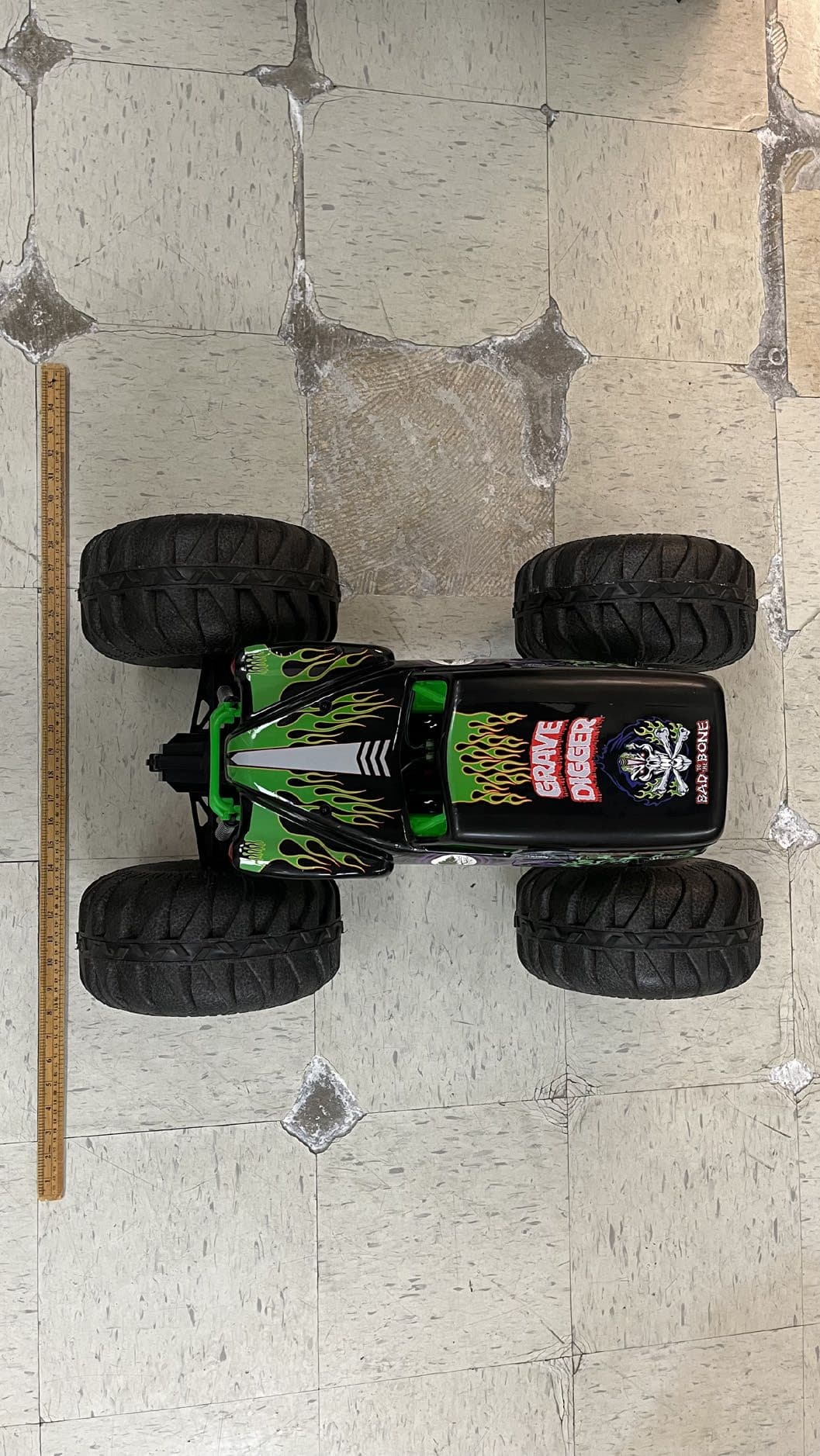
PQN66804RX2G43
Apr 03, 2024MJC Mega Grave Digger, MJC RDC Mega Grave Digger, MJC RDC Mega El Toro Loco, MNJ RDC Mega Megalodon RC, TRGT MIXED MEGA MJ HAFT PALLET, MJC COP Mega RC Asst PAL
Equipment Class
DXX - Part 15 Low Power Communication Device TransmitterPQN68126TX2G4
Aug 29, 2023HEX RDC HxmdPrSrEltStnrCrct EN GML2pkSLD
Equipment Class
DXX - Part 15 Low Power Communication Device Transmitter