PQTDORM02315 MHz KEYFOB TRANSMITTER
Dorman Products, Inc.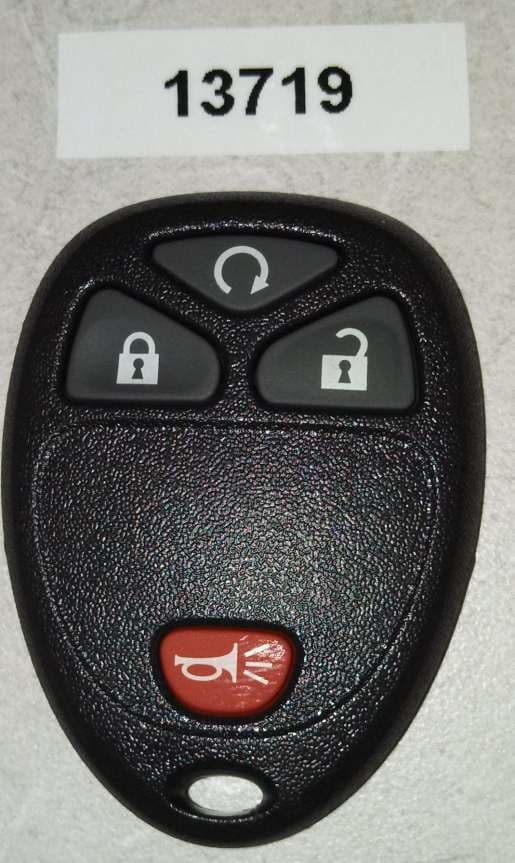
Click to zoom
Application Details
- Equipment Class
- DSC - Part 15 Security/Remote Control Transmitter
- Date of Grant
- Jan 14, 2013
- Application Purpose
- Original Equipment
- Date of Application
- Jan 14, 2013
- Equipment Note
- 315 MHz KEYFOB TRANSMITTER
- Frequency Range
- 315.00000000 - 315.00000000
- Company
- Dorman Products, Inc.
- Country
- United States
Documents & Files
Document Text
Text extracted from the exhibit documents filed with the FCC. Open a document above to read the original.
Users Manual
Use this Procedure for Vehicles with Driver Information Center Buttons This information is in your vehicle Owner’s Manual in the Drivers Information Center Section 1. Insert Key and turn to ON position so you can access Drivers Information Center 2. Press the vehicle’s information button until PRESS TO RELEARN REMOTE KEY displays. 3. Press the set/reset button until REMOTE KEY LEARNING ACTIVE displays. 4. Press and hold the lock and unlock buttons on the first keyless remote at the same time for approximately 15 seconds. A chime will sound indicating that the remote is programmed 5. To program additional remotes at this time repeat Step 4. This vehicle can have a maximum of eight remotes programmed. 6. To exit programming mode turn the key off and remove key. Test remote(s) FCC WARNING Statement 15.19(a)(3): This device complies with Part 15 of the FCC Rules. Operation is subject to the following two conditions: (1) this device may not cause harmful interference, and (2) this device must accept any interference received, including interference that may cause undesired operation. Changes or modifications not expressly approved by Dorman Products Inc. could void the user’s authority to operate the equipment. IC WARNING The term IC before the Certification/Registration number only signifies that the Industry Canada technical specifications were met. Operation is subject to the following two conditions: (1) this device may not cause interference, and (2) this device must accept any interference including interference that may cause undesired operation of the device.
Cover Letter(s)
NEW PRODUCTS. NEW SOLUTIONS. NEW OPPORTUNITIES. 3400 East Walnut Street • Colmar, PA 18915-1800 • Customer Service: 1-800-523-2492 • Fax: 859-567-7010 Dear Sir or Madam: The application for FCC certification PQTDORM02 will cover 13 unique part numbers, which are electrically identical. The PCBs and software are unchanged between each. The only differences are in the plastic case containing the PCB. Each PCB is equipped with 9 solder pads to accommodate the variety of button configurations. MODEL DESCRIPTION Buttons 13714 KEYLESS ENTRY REMOTE 6 13715 KEYLESS ENTRY REMOTE 4 13717 KEYLESS ENTRY REMOTE 3 13718 KEYLESS ENTRY REMOTE 5 13719 KEYLESS ENTRY REMOTE 4 13720 KEYLESS ENTRY REMOTE 5 13721 KEYLESS ENTRY REMOTE 4 13722 KEYLESS ENTRY REMOTE 4 13723 KEYLESS ENTRY REMOTE 5 13724 KEYLESS ENTRY REMOTE 4 13725 KEYLESS ENTRY REMOTE 5 13727 KEYLESS ENTRY REMOTE 6 13728 KEYLESS ENTRY REMOTE 5 Sincerely, Matthew Barnard Software Engineer Dorman Products, Inc.
ID Label/Location Info
Dorman Products, Inc. FCC ID: PQTDORM02 IC: 10735A-DORM02 Label Sample The XX in the Model is representative of any of the following Models submitted on this application: 13714 13715 13716 13718 13719 13720 13721 13722 13723 13724 13725 13727 13728 Dorman Products, Inc. Model: 137XX 961IN YYDDD FCC ID: PQTDORM02 IC: 10735A-DORM02
ID Label/Location Info
Dorman Products Inc. Model: 13714 961IN YYDDD FCC ID: PQTDORM02 IC: 10735A-DORM02
ID Label/Location Info
Dorman Products Inc. Model: 13715 961IN YYDDD FCC ID: PQTDORM02 IC: 10735A-DORM02
ID Label/Location Info
Dorman Products Inc. Model: 13716 961IN YYDDD FCC ID: PQTDORM02 IC: 10735A-DORM02
ID Label/Location Info
Dorman Products Inc. Model: 13717 961IN YYDDD FCC ID: PQTDORM02 IC: 10735A-DORM02
ID Label/Location Info
Dorman Products Inc. Model: 13718 961IN YYDDD FCC ID: PQTDORM02 IC: 10735A-DORM02
ID Label/Location Info
Dorman Products Inc. Model: 13719 961IN YYDDD FCC ID: PQTDORM02 IC: 10735A-DORM02
ID Label/Location Info
Dorman Products Inc. Model: 13720 961IN YYDDD FCC ID: PQTDORM02 IC: 10735A-DORM02
ID Label/Location Info
Dorman Products Inc. Model: 13721 961IN YYDDD FCC ID: PQTDORM02 IC: 10735A-DORM02
ID Label/Location Info
Dorman Products Inc. Model: 13722 961IN YYDDD FCC ID: PQTDORM02 IC: 10735A-DORM02
ID Label/Location Info
Dorman Products Inc. Model: 13723 961IN YYDDD FCC ID: PQTDORM02 IC: 10735A-DORM02
ID Label/Location Info
Dorman Products Inc. Model: 13724 961IN YYDDD FCC ID: PQTDORM02 IC: 10735A-DORM02
ID Label/Location Info
Dorman Products Inc. Model: 13725 961IN YYDDD FCC ID: PQTDORM02 IC: 10735A-DORM02
ID Label/Location Info
Dorman Products Inc. Model: 13726 961IN YYDDD FCC ID: PQTDORM02 IC: 10735A-DORM02
ID Label/Location Info
Dorman Products Inc. Model: 13727 961IN YYDDD FCC ID: PQTDORM02 IC: 10735A-DORM02
ID Label/Location Info
Dorman Products Inc. Model: 13728 961IN YYDDD FCC ID: PQTDORM02 IC: 10735A-DORM02
Operational Description
Operational Description PQTDORM02 The keyfob assembly consists of a plastic case with 3-6 button cutouts, a rubber button panel, and a PCB and battery. It generates an on-off keyed, Manchester encoded signal that is transmitted at 315mHz. The keyfob uses an integrated RF MCU that detects button presses and calculates and transmits an encoded signal to a receiver. This signal is generated by an internal software controlled transmitter inside the MCU. It contains no external resonator. The antenna is integrated into the PCB. The 13 keyfob models are electrically identical. The PCBs and software are exactly identical between each. Each model includes the same PCB which has 9 solder pads to accommodate the variety of different button configurations. MODEL DESCRIPTION Buttons 13714 KEYLESS ENTRY REMOTE 6 13715 KEYLESS ENTRY REMOTE 4 13717 KEYLESS ENTRY REMOTE 3 13718 KEYLESS ENTRY REMOTE 5 13719 KEYLESS ENTRY REMOTE 4 13720 KEYLESS ENTRY REMOTE 5 13721 KEYLESS ENTRY REMOTE 4 13722 KEYLESS ENTRY REMOTE 4 13723 KEYLESS ENTRY REMOTE 5 13724 KEYLESS ENTRY REMOTE 4 13725 KEYLESS ENTRY REMOTE 5 13727 KEYLESS ENTRY REMOTE 6 13728 KEYLESS ENTRY REMOTE 5
Parts List/Tune Up Info
Silabs GM Remote 4R 0 Build Bom 6/27/2012 item qty Package Value Description MFG MFG Part Number POPULATE references 1 7 PCB_CONTACT_BTN MECH PCB TRACE CONTACT BUTTON (NOT A PART) DNP SW1,SW2,SW3,SW4,SW5,SW6,SW7 2 1 NX5032GA 12M CRYSTAL 12.000000 MHZ 8PF SMD NDK NX5032GA ‐ 12.000000MHZ DNP Y1 3 2 SM0402 3.9pF CAP CER 3.9PF 50V NP0 0402 MURATA GJM1555C1H3R9CB01D C9,C10 4 1 SM0402 0.22uH INDUCTOR 220NH 120MA 0402 MURATA LQG15HSR22J02D L1 5 1 HEADER 5 CONN HEADER .050" 5POS PCB GOLD SULLINS GRPB051VWVN ‐ RC DNP J1 6 1 SM0402 2.2uF CAP CERAMIC 2.2UF 6.3V X5R 0402 PANASONIC ECJ ‐ 0EB0J225M C6 7 1 SM0402 68pF CAP CER 68PF 50V 5% NP0 0402 MURATA GRM1555C1H680JZ01D C7 8 1 SOIC14_silabs IC TX 27 ‐ 960MHZ 3.6V 14SOIC SILABS SI4010 ‐ C2 ‐ GS U1 9 1 SM0402 0.001uF CAP CER 1000PF 50V 10% X7R 0402 MURATA GCM155R71H102KA37D C5 10 1 SM0603 8pF CAP CER 8PF 50V C0G 0.5PF 0603 XICON 140 ‐ CC504N8.0D DNP C4 11 1 SM0402 12pF CAP CER 12PF 50V 5% C0G 0402 MURATA GRM1555C1H120JZ01D C8 12 1 COIN_HLDR_CR2032_BK ‐ 913 COIN CELL RETAINER FOR 20MM DIA BATTERIES (CR2032) MEMORY PROTECTION DEVICES INC. BK ‐ 913 BATT1
Test Report
Retlif Testing Laboratories R Report No. R-1891P-1 Page 2 of 25 Technical Information Report Number: R-1891P-1 Customer: Dorman Products, Inc. Address: 3400 East Walnut Street Colmar, PA 18915 Manufacturer: SRM Technologies Pvt Ltd. Manufacturer Address: Lords Block-II, 1 st Floor Plot Nos 1&2 (NP), Northern Extension Area Thiru.Vi.Ka Industrial Estate, Eddatuthangal Guindy, Chennai – 600 032 Test Sample: 315 MHz Keyfob Transmitter Model Numbers: 13714, 13715, 13716, 13718, 13719, 13720, 13721, 13722, 13723, 13724, 13725, 13727, 13728 FCC ID: PQTDORM02 IC: 10735A-DORM02 Type: Security / Remote Control Transmitter Power Requirements: 3 VDC Derived from a CR2032 Battery Frequency of Operation: 315 MHz Equipment Class: DSC Equipment Use: Portable < 2.5 cm Test Specification: FCC Rules and Regulations Part 15, Subpart C, Section 15.231 Radio Standards Specification, RSS-210, Issue 8, June, 2010 Test Procedure: ANSI C63.4:2003 RSS-GEN, Issue 3, December 2010 Retlif Testing Laboratories R Report No. R-1891P-1 Page 3 of 25 Tests Performed The test methods performed on the 315 MHz Keyfob Transmitter are shown below: FCC Part 15, Subpart C Industry Canada RSS-210 Industry Canada RSS-GEN Test Method 15.231(b) A1.1.2(1) N/A Field Strength of Emissions 15.231(b)(2) A1.1.2(2) 4.5 Duty Cycle Determination 15.231(b)(3) A1.1.2(3) N/A Field Strength of Spurious Emissions 15.231(c) A1.1.3 N/A Bandwidth of Emission General Test Requirements 1. The measurement procedures of ANSI C63.4:2003 were utilized as specified in FCC Part 15, Subpart C, Section 15.31(a)(3) and IC RSS-GEN Section 4.1. 2. All radiated emissions measurements were performed on an Open Area Test Site (OATS), listed with the FCC and IC, in accordance with FCC Section 15.31(d) and IC Section 4.2. 3. The level of the fundamental field strength was recorded with a new battery installed in the EUT, in accordance with FCC Section 15.231(e) and IC Section 4.3(e). 4. All measurements were performed at the specified 3 meter test distance as required by FCC Section 15.31(f) and IC Section 7.25. 5. The EUT was rotated throughout 360 degrees for all radiated emissions measurements as specified in FCC Section 15.31(f)(5) and IC Section 4.3(h). 6. All readily accessible EUT controls were adjusted in such a manner as to maximize the level of emissions in accordance with FCC Section 15.31(g) and IC Section 4.3(h). 7. Appropriate accessories were attached to all EUT ports during the performance of radiated emissions measurements as required by FCC Section 15.31(i) and IC Section 4.3(d). 8. The EUT operated at a discrete frequency of 315 MHz. 9. The frequency spectrum was investigated from the lowest frequency generated in the device up to the 10 th harmonic of the highest fundamental frequency in accordance with FCC Section 15.33(a)(1) and IC Section 4.9. 10. All measurements were taken with a peak detector function as specified in FCC Section 15.35(a) and IC Section 4.4. The duty cycle, calculated in accordance with FCC Section 15.35(c) and IC Section 4.5, was applied to the peak readings in order to obtain the average value of emissions. The peak value of emissions was verified to meet the 20 dB requirement of FCC Section 15.35(b) and IC Section 7.2.1. Retlif Testing Laboratories R Report No. R-1891P-1 Page 5 of 25 Requirements and Test Results Requirement: FCC Section 15.231(a) - Periodic operation in the band 40.66 - 40.7 MHz and above 70 MHz The provisions of this Section are restricted to periodic operation within the band 40.66-40.7 MHz and above 70 MHz. Except as shown in Paragraph (e) of this Section, the intentional radiator is restricted to the transmissions of a control signal such as those used with alarm systems, door openers, remote switches, etc. Continuous transmissions, voice, video and the radio control of toys are not permitted. Data is permitted to be sent with a control signal. IC RSS-210, A1.1 - Momentarily Operated Devices The frequency bands and field strength limits in Tables 4 and 5 are only for the transmission of a control signal such as that used with alarm systems, door openers, remote switches, etc. Radio control of toys or model aircrafts, and continuous transmissions such as voice or video are not permitted except as provided in A1.1.5. Data is permitted to be sent with a control signal. Results: The device was operated at a frequency of 315 MHz and is for the transmission of a control signal used for remote keyless vehicle entry. Requirement: FCC Sections 15.231(a)(1)-(5) Periodic operation in the band 40.66 - 40.7 MHz and above 70 MHz The following conditions were met in order to comply with the provisions for momentary operation: IC RSS-210, A1.1.1(a)-(d) - Types of Momentary Signals The following conditions were met in order to comply with the provisions for momentary operation: FCC 15.231(a)(1): A manually operated transmitter shall employ a switch that will automatically deactivate the transmitter within not more than 5 seconds of being released. IC A1.1.1(a): A manually operated transmitter shall employ a push-to-operate switch and be under manual control at all transmission times. When released, the transmitter shall cease transmission (holdover time of up to 5 seconds of operation). Results: The device is a manually operated, push to operate transmitter under manual control. The device ceased transmission within 5 seconds of deactivation. Retlif Testing Laboratories R Report No. R-1891P-1 Page 6 of 25 Requirements and Test Results (con’t) FCC 15.231(a)(2): A transmitter activated automatically shall cease transmission within 5 seconds after activation. IC A1.1.1(b): A transmitter activated automatically shall cease transmission with 5 seconds after activation, (i.e. maximum 5 seconds of operation). Results: Transmission is not automatically activated. FCC 15.231(a)(3): Periodic transmissions at regular predetermined intervals are not permitted. However, polling or supervision transmissions, including data, t…
Text truncated - open the document above for the full version.
Test Setup Photos
Page 1 of 4 Dorman Products, Inc. Test Setup Photographs FCC ID: PQTDORM02 IC: 10735A-DORM02 Page 2 of 4 Field Strength of Emissions (Fundamental and Spurious) Test Setup Photographs Test Setup Horizontal Antenna Polarization Page 3 of 4 Field Strength of Emissions Test Setup Photographs Vertical Antenna Polarization Page 4 of 4 Duty Cycle Determination and Bandwidth of Emissions Test Setup Photographs Test Setup
Contact Information
Applicant
Joseph Braun(General Counsel)
Test Firm
Retlif Testing LaboratoriesMichael Bozza
Technical Specifications
| # | Rule Parts | Frequency Range | Power Output |
|---|---|---|---|
| 1 | 15.231 | 315 MHz - 315 MHz | - |
Other Applications from Dorman Products, Inc.
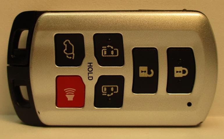
PQTDORM42
Jun 01, 2020315 MHz Keyfob Transmitter
Equipment Class
DSC - Part 15 Security/Remote Control Transmitter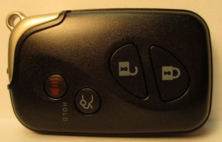
PQTDORM48
May 23, 2020315 MHz Keyfob Transmitter
Equipment Class
DSC - Part 15 Security/Remote Control Transmitter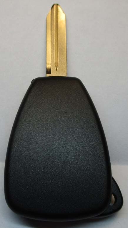
PQTDORM49
May 20, 2020315 MHz Keyfob Transmitter
Equipment Class
DSC - Part 15 Security/Remote Control Transmitter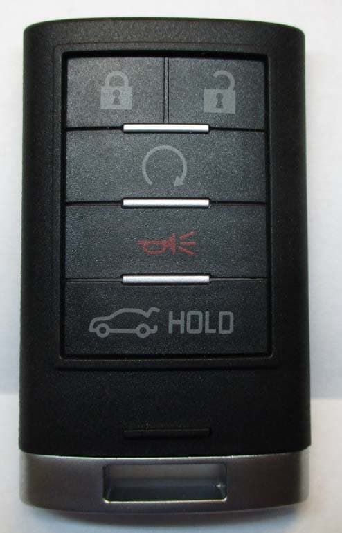
PQTDORM25
May 20, 2020315 MHz Keyfob Transmitter
Equipment Class
DSC - Part 15 Security/Remote Control Transmitter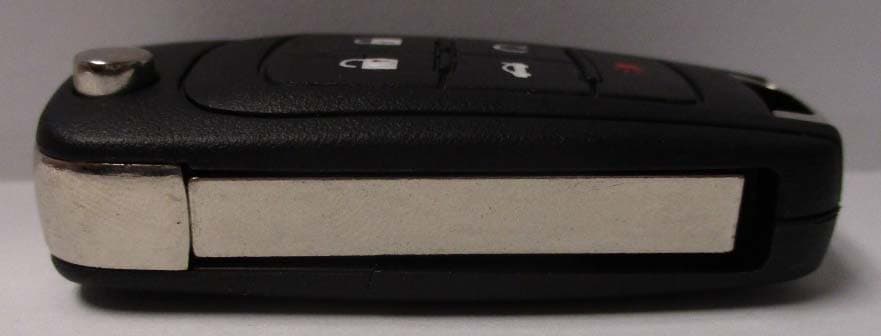
PQTDORM44
May 12, 2020315 MHz Keyfob Transmitter
Equipment Class
DSC - Part 15 Security/Remote Control Transmitter