PQTDORM11315 MHz Keyfob Transmitter
Dorman Products, Inc.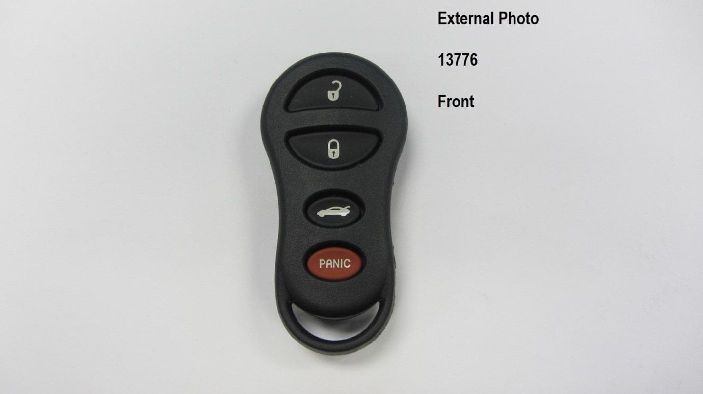
Click to zoom
Application Details
- Equipment Class
- DSC - Part 15 Security/Remote Control Transmitter
- Date of Grant
- Dec 21, 2015
- Application Purpose
- Original Equipment
- Date of Application
- Dec 21, 2015
- Equipment Note
- 315 MHz Keyfob Transmitter
- Frequency Range
- 315.00000000 - 315.00000000
- Company
- Dorman Products, Inc.
- Country
- United States
Documents & Files
Document Text
Text extracted from the exhibit documents filed with the FCC. Open a document above to read the original.
Users Manual
ALL KEY FOBS MUST BE PRESENT AND REPROGRAMMED WHEN PROGRAMMING NEW FOBS Programming Instructions: 1) Turn vehicle ignition key to ON position, without starting engine (Key-On Engine-Off - Position "1"). 2) Insert Programmer into OBD / DLC port - located under steering column, near pedals. 3) A Chime sounds for 1 second Indicating programming mode is active. 4) Press the LOCK & UNLOCK buttons on the Key-Fob simultaneously for 3 seconds. Press the UNLOCK button for 2 seconds. 5) Repeat step 4 for all additional remotes. 6) When all Key fobs have been programmed, turn ignition key off and remove programmer from the OBD / DLC port. 7) Wait 2 minutes and verify each Key fob functions properly. If programming was unsuccessful, restart the procedure. FCC WARNING Statement 15.19(a)(3): This device complies with Part 15 of the FCC Rules. Operation is subject to the following two conditions: (1) this device may not cause harmful interference, and (2) this device must accept any interference received, including interference that may cause undesired operation. Changes or modifications not expressly approved by Dorman Products Inc. could void the user’s authority to operate the equipment. IC WARNING The term IC before the Certification/Registration number only signifies that the Industry Canada technical specifications were met. Operation is subject to the following two conditions: (1) this device may not cause interference, and (2) this device must accept any interference including interference that may cause undesired operation of the device. Le présent appareil est conforme aux CNR d'Industrie Canada applicables aux appareils radio exempts de licence. L'exploitation est autorisée aux deux conditions suivantes : (1) l'appareil ne doit pas produire de brouillage, et (2) l'utilisateur de l'appareil doit accepter tout brouillage radioélectrique subi, même si le brouillage est susceptible d'en compromettre le fonctionnement.
External Photos
External Photo 99164 Front External Photo 99164 Back
Internal Photos
Internal w/PCBA 13776 & 99164 Back Internal w/PCBA 13776 & 99164 Front Internal Photo 13776 & 99164 Front/Back
Operational Description
Operational Description: PQTDORM11 The keyfob assembly consists of a plastic case with 3 or 4 button cutouts, a rubber button panel, and a PCB and battery. It generates an on-off keyed, Manchester encoded signal that is transmitted at 315mHz. The keyfob uses an integrated RF MCU that detects button presses and calculates and transmits an encoded signal to a receiver. This signal is generated by an internal software controlled transmitter inside the MCU. It contains no external resonator. The antenna is integrated into the PCB. MODEL DESCRIPTION Buttons 13776 KEYLESS ENTRY REMOTE 4 99164 KEYLESS ENTRY REMOTE 3
Parts List/Tune Up Info
ITEM QTY PACKAGEVALUEDESCRIPTIONMFG MFG PART NUMBERCOSTTOTALPOPULATEREFERENCES 14PCB_CONTACT_BTN MECH PCB TRACE CONTACT BUTTON (NOT A PART) SW1,SW2,SW3,SW4 25TESTPAD TESTPAD TP1,TP2,TP3,TP4,TP5 33SM0402 3.9pF CAP CER 3.9PF 50V NP0 0402 MURATA GJM1555C1H3R9CB01D C2,C3,C4 41SM0402 0.22uH INDUCTOR 220NH 120MA 0402 MURATA LQG15HSR22J02D L1 51SM0402 2.2uF CAP CERAMIC 2.2UF 6.3V X5R 0402PANASONIC ECJ-0EB0J225M C6 61SM0402 68pF CAP CER 68PF 50V 5% NP0 0402 MURATA GRM1555C1H680JZ01D C7 71SOIC14_silabs IC TX 27-960MHZ FSK 3.6V 14SOICSILABS SI4010-C2-GS U1 81SM0402 0.001uF CAP CER 1000PF 50V 10% X7R 0402MURATA GCM155R71H102KA37D C5 91SM0402 12pF CAP CER 12PF 50V 5% C0G 0402 MURATA GRM1555C1H120JZ01D C1 101SO8 Any PIC MCU - Licensing PurposesMicrochipAny U2
Test Report
Report No. R-2365P Page 2 of 24 Retlif Testing Laboratories R Technical Information Report Number: R-2365P Customer: Dorman Products, Inc. Address: 3400 East Walnut Street Colmar, PA 18915 Manufacturer: Dorman Products, Inc. Manufacturer Address: Dorman Products, Inc. 3400 East Walnut Street Colmar, PA 18915 Test Sample: 315 MHz Keyfob Transmitter Model Number: 13776 and 99164 FCC ID: PQTDORM11 IC: 10735A-DORM11 Type: Security / Remote Control Transmitter Power Requirements: 3 VDC Derived from a CR2032 Battery Frequency of Operation: 315 MHz Equipment Class: DSC Equipment Use: Portable < 2.5 cm Test Specification: FCC Rules and Regulations Part 15, Subpart C, Section 15.231 Radio Standards Specification, RSS-210, Issue 8, June, 2010 Test Procedure: ANSI C63.4:2014 RSS-GEN, Issue 4, November 2014 Test Facility: Retlif Testing Laboratories 3131 Detwiler Road Harleysville, PA 19438 FCC Registered Test Site Number: 98314 Report No. R-2365P Page 3 of 24 Retlif Testing Laboratories R Tests Performed The test methods performed on the 315 MHz Keyfob Transmitter are shown below: FCC Part 15, Subpart C Industry Canada RSS-210 Industry Canada RSS-GEN Test Method 15.231(b) A1.1.2(1) N/A Field Strength of Emissions 15.231(b)(2) A1.1.2(2) 4.5 Duty Cycle Determination 15.231(b)(3) A1.1.2(3) N/A Field Strength of Spurious Emissions 15.231(c) A1.1.3 N/A Bandwidth of Emission General Test Requirements 1. The measurement procedures of ANSI C63.4:2009 were utilized as specified in FCC Part 15, Subpart C, Section 15.31(a)(3) and IC RSS-GEN Section 4.1. 2. All radiated emissions measurements were performed on an Open Area Test Site (OATS), listed with the FCC and IC, in accordance with FCC Section 15.31(d) and IC Section 4.2. 3. The level of the fundamental field strength was recorded with a new battery installed in the EUT, in accordance with FCC Section 15.231(e) and IC Section 4.3(e). 4. All measurements were performed at the specified 3 meter test distance as required by FCC Section 15.31(f) and IC Section 7.25. 5. The EUT was rotated throughout 360 degrees for all radiated emissions measurements as specified in FCC Section 15.31(f)(5) and IC Section 4.3(h). 6. All readily accessible EUT controls were adjusted in such a manner as to maximize the level of emissions in accordance with FCC Section 15.31(g) and IC Section 4.3(h). 7. Appropriate accessories were attached to all EUT ports during the performance of radiated emissions measurements as required by FCC Section 15.31(i) and IC Section 4.3(d). 8. The EUT operated at a discrete frequency of 315 MHz. 9. The frequency spectrum was investigated from the lowest frequency generated in the device up to the 10 th harmonic of the highest fundamental frequency in accordance with FCC Section 15.33(a)(1) and IC Section 4.9. 10. All measurements were taken with a peak detector function as specified in FCC Section 15.35(a) and IC Section 4.4. The duty cycle, calculated in accordance with FCC Section 15.35(c) and IC Section 4.5, was applied to the peak readings in order to obtain the average value of emissions. The peak value of emissions was verified to meet the 20 dB requirement of FCC Section 15.35(b) and IC Section 7.2.1. Report No. R-2365P Page 5 of 24 Retlif Testing Laboratories R Requirements and Test Results Requirement: FCC Section 15.231(a) - Periodic operation in the band 40.66 - 40.7 MHz and above 70 MHz The provisions of this Section are restricted to periodic operation within the band 40.66-40.7 MHz and above 70 MHz. Except as shown in Paragraph (e) of this Section, the intentional radiator is restricted to the transmissions of a control signal such as those used with alarm systems, door openers, remote switches, etc. Continuous transmissions, voice, video and the radio control of toys are not permitted. Data is permitted to be sent with a control signal. IC RSS-210, A1.1 - Momentarily Operated Devices The frequency bands and field strength limits in Tables 4 and 5 are only for the transmission of a control signal such as that used with alarm systems, door openers, remote switches, etc. Radio control of toys or model aircrafts, and continuous transmissions such as voice or video are not permitted except as provided in A1.1.5. Data is permitted to be sent with a control signal. Results: The device was operated at a frequency of 315 MHz and is for the transmission of a control signal used for remote keyless vehicle entry. Requirement: FCC Sections 15.231(a)(1)-(5) Periodic operation in the band 40.66 - 40.7 MHz and above 70 MHz The following conditions were met in order to comply with the provisions for momentary operation: IC RSS-210, A1.1.1(a)-(d) - Types of Momentary Signals The following conditions were met in order to comply with the provisions for momentary operation: FCC 15.231(a)(1): A manually operated transmitter shall employ a switch that will automatically deactivate the transmitter within not more than 5 seconds of being released. IC A1.1.1(a): A manually operated transmitter shall employ a push-to-operate switch and be under manual control at all transmission times. When released, the transmitter shall cease transmission (holdover time of up to 5 seconds of operation). Results: The device is a manually operated, push to operate transmitter under manual control. The device ceased transmission within 5 seconds of deactivation. Report No. R-2365P Page 6 of 24 Retlif Testing Laboratories R Requirements and Test Results (con’t) FCC 15.231(a)(2): A transmitter activated automatically shall cease transmission within 5 seconds after activation. IC A1.1.1(b): A transmitter activated automatically shall cease transmission with 5 seconds after activation, (i.e. maximum 5 seconds of operation). Results: Transmission is not automatically activated. FCC 15.231(a)(3): Periodic transmissions at regular predetermined intervals are not permitted. However, polling or supervision transmissions, including data, to determine system integrity of transmitter…
Text truncated - open the document above for the full version.
Test Setup Photos
Page 1 of 8 Dorman Products, Inc. Test Setup Photographs FCC ID: PQTDORM11 IC: 10735A-DORM11 Page 2 of 8 Field Strength of Emissions Test Setup Photographs Test Setup, X Axis Test Setup, Y Axis Page 3 of 8 Field Strength of Emissions Test Setup Photographs Test Setup, Z Axis Page 4 of 8 Field Strength of Emissions Test Setup Photographs Horizontal Antenna Polarization, Below 1 GHz Vertical Antenna Polarization, Below 1 GHz Page 5 of 8 Field Strength of Emissions Test Setup Photographs Horizontal Antenna Polarization, Above 1 GHz Vertical Antenna Polarization, Above 1 GHz Page 6 of 8 Field Strength of Spurious Emissions Test Setup Photographs EUT Test Setup Horizontal Antenna Polarization Page 7 of 8 Field Strength of Spurious Emissions Test Setup Photographs Vertical Antenna Polarization Page 8 of 8 Duty Cycle Determination and Bandwidth of Emissions Test Setup Photographs Test Setup
Contact Information
Applicant
Joseph Braun(General Counsel)
Test Firm
Retlif Testing LaboratoriesMichael Bozza
Technical Specifications
| # | Rule Parts | Frequency Range | Power Output |
|---|---|---|---|
| 1 | 15.231 | 315 MHz - 315 MHz | - |
Other Applications from Dorman Products, Inc.
PQTDORM42
Jun 01, 2020315 MHz Keyfob Transmitter
Equipment Class
DSC - Part 15 Security/Remote Control Transmitter
PQTDORM48
May 23, 2020315 MHz Keyfob Transmitter
Equipment Class
DSC - Part 15 Security/Remote Control Transmitter
PQTDORM49
May 20, 2020315 MHz Keyfob Transmitter
Equipment Class
DSC - Part 15 Security/Remote Control Transmitter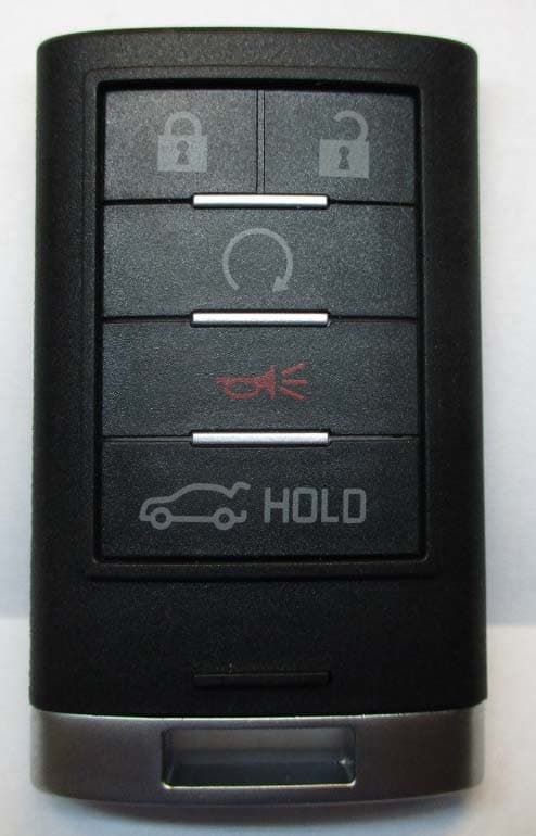
PQTDORM25
May 20, 2020315 MHz Keyfob Transmitter
Equipment Class
DSC - Part 15 Security/Remote Control Transmitter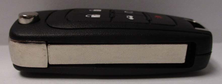
PQTDORM44
May 12, 2020315 MHz Keyfob Transmitter
Equipment Class
DSC - Part 15 Security/Remote Control Transmitter