PQTDORM17315 MHz Keyfob Transmitter
Dorman Products, Inc.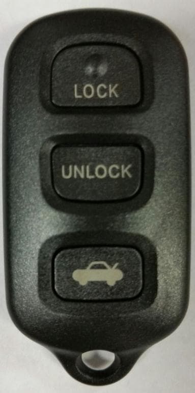
Click to zoom
Application Details
- Equipment Class
- DSC - Part 15 Security/Remote Control Transmitter
- Date of Grant
- Dec 23, 2015
- Application Purpose
- Original Equipment
- Date of Application
- Dec 23, 2015
- Equipment Note
- 315 MHz Keyfob Transmitter
- Frequency Range
- 315.00000000 - 315.00000000
- Company
- Dorman Products, Inc.
- Country
- United States
Documents & Files
Document Text
Text extracted from the exhibit documents filed with the FCC. Open a document above to read the original.
Users Manual
ALL KEY FOBS MUST BE PRESENT AND REPROGRAMMED WHEN PROGRAMMING NEW FOBS Programming Instructions: 1. Open & unlock driver door. 2. Within 5 seconds, insert and remove the key in the ignition 2 times. (Do not turn on) 3. Close and open driver door 2 times. 4. Insert and remove the key in the ignition. 5. Close and open driver door 2 times. 6. Close the driver door. 7. Turn the key to the on position (without cranking ), and then turn off and remove the key from the ignition. 8. The power door locks will cycle when you have successfully entered programming mode. 9. Press lock & unlock buttons simultaneously for 1 second. Press unlock button for 2 seconds. Door locks will cycle 1 time to confirm successful programming. Repeat this step to program all additional remotes. 10. Open the driver door and test all remotes. If programming has failed, repeat this procedure from the beginning. FCC WARNING Statement 15.19(a)(3): This device complies with Part 15 of the FCC Rules. Operation is subject to the following two conditions: (1) this device may not cause harmful interference, and (2) this device must accept any interference received, including interference that may cause undesired operation. Changes or modifications not expressly approved by Dorman Products Inc. could void the user’s authority to operate the equipment. ALL KEY FOBS MUST BE PRESENT AND REPROGRAMMED WHEN PROGRAMMING NEW FOBS IC WARNING This device complies with Industry Canada’s license-exempt RSSs. Operation is subject to the following two conditions: (1) This device may not cause interference; and (2) This device must accept any interference, including interference that may cause undesired operation of the device. FVIN: 6399139IC MISE EN GARDE IC- Le terme IC avant le numero de dertification/enregistrement signifie seulement que les specifications techniques d’Industrie Canada ont ete rencontrees. Le fonctionnement est sujet aux deux conditions suivantes: (1) cet appareil ne doit pas causer d’interference, et (2) cet appareil doit pouvoir accepter toute intergerence recue, incluant l’interference qui peut engendrer un fonctionnement non desire de l’appareil. ALL KEY FOBS MUST BE PRESENT AND REPROGRAMMED WHEN PROGRAMMING NEW FOBS
External Photos
External 99139 Front/Back External 99141 Front/Back
Internal Photos
Internal Front w/PCBA 99141 Front/Back
Operational Description
Operation Instruction PTQDORM17 The keyfob assembly consists of a plastic case with 3 or 4 button cutouts, a rubber button panel, a PCB and battery. It generates a Manchester encoded signal that is transmitted at 315MHz. The keyfob uses an integrated RF MCU that detects button presses and calculates and transmits an encoded signal to a receiver. This signal is generated by an internal software controlled transmitter inside the MCU. It contains no external resonator. The antenna is integrated into the PCB. MODEL DESCRIPTION Buttons 99139 KEYLESS ENTRY REMOTE 3 99141 KEYLESS ENTRY REMOTE 4
Parts List/Tune Up Info
Designator DescriptionFootprint Quantity R1, R2, R4, R5 Resistor6034 C2 Ceramic Chip Capacitor6031 C1 Ceramic Chip Capacitor6031 C5 Ceramic Chip Capacitor6031 C3Ceramic Chip Capacitor12061 L1,L2 Ceramic Chip Capacitor6032 U1 ISM Transmitter IC -SI4010-C2-GTR MSOP-10 1 S1, S2, S34.2*3.2 SMT Tact SwitchSW4 3 S4 5.2 * 5.2 SMD Tact Switch 5.2*5.2*.081 BT1Battery Terminal20321 Value 1.5K(152) 8.2pF 100pF 100nF 2.2uF 100nH
Test Setup Photos
Page 1 of 10 Dorman Products, Inc. Test Setup Photographs FCC ID: PQTDORM17 IC: 10735A-DORM17 Page 2 of 10 Field Strength of Emissions Test Setup Photographs Test Setup, X Axis Test Setup, Y Axis Page 3 of 10 Field Strength of Emissions Test Setup Photographs Test Setup, Z Axis Page 4 of 10 Field Strength of Emissions Test Setup Photographs Horizontal Antenna Polarization, 30 to 200 MHz Vertical Antenna Polarization, 30 to 200 MHz Page 5 of 10 Field Strength of Emissions Test Setup Photographs Horizontal Antenna Polarization, 200 to 1000 MHz Vertical Antenna Polarization, 200 to 1000 MHz Page 6 of 10 Field Strength of Emissions Test Setup Photographs Horizontal Antenna Polarization, Above 1 GHz Vertical Antenna Polarization, Above 1 GHz Page 7 of 10 Field Strength of Spurious Emissions Test Setup Photographs Horizontal Antenna Polarization, 30 to 200 MHz Vertical Antenna Polarization, 30 to 200 MHz Page 8 of 10 Field Strength of Spurious Emissions Test Setup Photographs Horizontal Antenna Polarization, 200 to 1000 MHz Vertical Antenna Polarization, 200 to 1000 MHz Page 9 of 10 Duty Cycle Determination Test Setup Photographs Test Setup, Oscilloscope Test Setup, Spectrum Analyzer Page 10 of 10 Occupied Bandwidth Test Setup Photographs Test Setup
Contact Information
Applicant
Joseph Braun(General Counsel)
Test Firm
Retlif Testing LaboratoriesMichael Bozza
Technical Specifications
| # | Rule Parts | Frequency Range | Power Output |
|---|---|---|---|
| 1 | 15.231 | 315 MHz - 315 MHz | - |
Other Applications from Dorman Products, Inc.
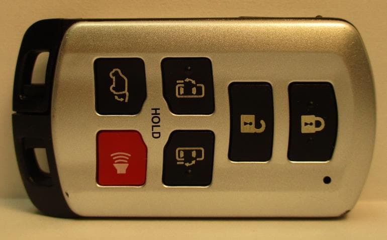
PQTDORM42
Jun 01, 2020315 MHz Keyfob Transmitter
Equipment Class
DSC - Part 15 Security/Remote Control Transmitter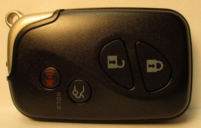
PQTDORM48
May 23, 2020315 MHz Keyfob Transmitter
Equipment Class
DSC - Part 15 Security/Remote Control Transmitter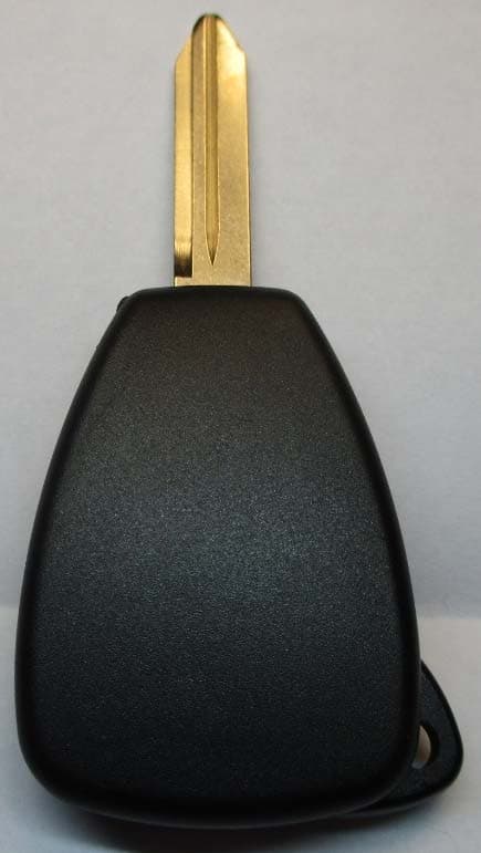
PQTDORM49
May 20, 2020315 MHz Keyfob Transmitter
Equipment Class
DSC - Part 15 Security/Remote Control Transmitter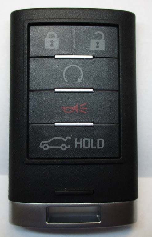
PQTDORM25
May 20, 2020315 MHz Keyfob Transmitter
Equipment Class
DSC - Part 15 Security/Remote Control Transmitter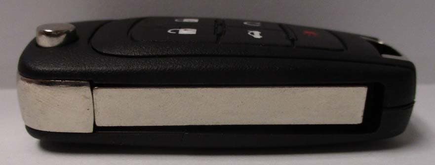
PQTDORM44
May 12, 2020315 MHz Keyfob Transmitter
Equipment Class
DSC - Part 15 Security/Remote Control Transmitter