PRDLAWIRPMU24Wireless Mouse
Acrox Technologies Co., Ltd.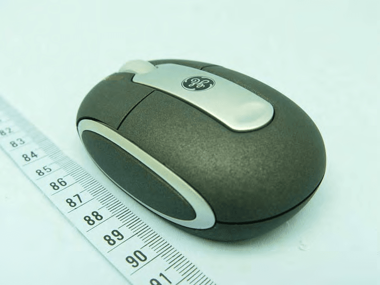
Click to zoom
Application Details
- Equipment Class
- DXX - Part 15 Low Power Communication Device Transmitter
- Date of Grant
- Jan 20, 2011
- Application Purpose
- Original Equipment
- Date of Application
- Jan 20, 2011
- Equipment Note
- Wireless Mouse
- Frequency Range
- 2403.00000000 - 2480.00000000
- Company
- Acrox Technologies Co., Ltd.
- Country
- Taiwan
Documents & Files
Document Text
Text extracted from the exhibit documents filed with the FCC. Open a document above to read the original.
Users Manual
Wireless Mini Laser Mouse Instruction Manual 98765 For technical support contact Jasco Products at 1-800-654-8483 or visit www.jascoproducts.com 4/10 11/10 2 Table of Contents PACKAGE CONTENTS .............................................................................................................2 SYSTEM REQUIREMENTS .....................................................................................................2 SAFETY STANDARDS ..............................................................................................................2 POWER SAVING FEATURES ................................................................................................3 BATTERY INSTALLATION .......................................................................................................3 HARDWARE INSTALLATION ................................................................................................3 TROUBLE SHOOTING .............................................................................................................3 TWO YEAR LIMITED WARRANTY .....................................................................................4 FCC STATEMENT ........................................................................................................................4 Package Contents • Wireless Mini Laser Mouse • Nano USB Receiver • 2 AAA batteries System Requirements • Windows ® 2000, XP, Vista, Windows 7 • Mac 10.1 or higher • Available USB Port Laser Safety Notice 1) This device is a class 1 laser as defined in 21 CFR 1040.10. These lasers are safe; however, it is recommended that you do not point the laser beam directly into your eye or anyone else’s eyes. 2) Your product complies with FCC and CE rules. 3) This product has no serviceable parts. Use of controls or adjustments of procedures other than the user guide may be hazardous to your health. CAUTION Batteries may leak harmful liquids or ignitable materials or explode causing injury and product damage. • Do not mix old and new or other battery types. • Replace all batteries at the same time. • Replace fully discharged batteries immediately. 3 Power Saving Features • Your mouse can be turned off to conserve the battery when not in use. The on/off switch is located on the bottom of the mouse. • The mouse will go to sleep when idle for a long period of time to save batteries. To wake the mouse, Simply move it and it will wake up. Battery Installation 1) Open the battery compartment on the bottom of the mouse. Insert 2 AAA batteries, being sure to match the polarity of the batteries with the polarity markings inside the battery compartment. 2) Replace the battery compartment cover. Hardware Installation Please keep these directions in a safe place. 1) Insert the enclosed batteries into the battery compartment of your mouse. 2) Make sure your mouse is on. There is an on/off switch located on the bottom of your mouse. 3) Plug the Laser Mini Mouse Nano receiver into an available USB port on your computer or USB hub, wait a few seconds. 4) Your mouse should now function normally. Move your mouse to test functionality. *When traveling receiver can be stored magnetically in the bottom of the mouse Trouble Shooting • Mouse does not work properly - If your mouse has been idle for a period of time it may be asleep to conserve battery power. Press the left mouse button to wake it. • Mouse will not move - Make sure you have installed all updates to your operating system. - Press your left mouse button to wake your mouse. - Change the batteries on your mouse. Power Saving Features • Your mouse can be turned off to conserve the battery when not in use. The on/off switch is located on the bottom of the mouse. • The mouse will go to sleep when idle for a long period of time to save batteries. To wake the mouse, Simply move it and it will wake up. Battery Installation 1) Open the battery compartment on the bottom of the mouse. Insert 2 AAA batteries, being sure to match the polarity of the batteries with the polarity markings inside the battery compartment. 2) Replace the battery compartment cover. Hardware Installation Please keep these directions in a safe place. 1) Insert the enclosed batteries into the battery compartment of your mouse. 2) Make sure your mouse is on. There is an on/off switch located on the bottom of your mouse. 3) Plug the Laser Mini Mouse Nano receiver into an available USB port on your computer or USB hub, wait a few seconds. 4) Your mouse should now function normally. Move your mouse to test functionality. *When traveling receiver can be stored magnetically in the bottom of the mouse Trouble Shooting • Mouse does not work properly - If your mouse has been idle for a period of time it may be asleep to conserve battery power. Press the left mouse button to wake it. • Mouse will not move - Make sure you have installed all updates to your operating system. - Press your left mouse button to wake your mouse. - Change the batteries on your mouse. Battery Installation 1) Slide the top corner of the mouse off to open the battery compartment. Insert 2 AAA batteries, being sure to match the polarity of the batteries with the polarity markings inside the battery compartment. 2) Replace the battery compartment cover. 4 Two Year Limited Warranty Jasco Products Company warrants this product to be free from manufacturing defects for a period of two years from the original date of consumer purchase. This warranty is limited to the repair or replacement of this product only and does not extend to consequen- tial or incidental damage to other products that may be used with this unit. This warranty is in lieu of all other warranties express or implied. Some states do not allow limitations on how long an implied warranty lasts or permit the exclusion or limitation of incidental or consequential damages, so the above limitations may not apply to you. This warranty gives you specific rights, and you may also have other rights which vary…
Text truncated - open the document above for the full version.
External Photos
Page 1 CONSTRUCTION PHOTOS OF EUT
ID Label/Location Info
Wireless
ID Label/Location Info
Label Location
Internal Photos
Page 2 Page 3 Page 4
Operational Description
FCC ID: PRDLAWIRPMU24 Report No.: RF991224C07 Operational Description This device is a Wireless Mouse. The transmitter of the EUT is powered by 3Vdc from batteries. The antenna is printed antenna without antenna connectors. The other instruction, please have a look at the users manual.
Test Report
Report No.: RF991224C07 1 Report Format Version 4.0.0 FCC TEST REPORT REPORT NO. :RF991224C07 MODEL NO. :MPP FCC ID:PRDLAWIRPMU24 RECEIVED :Dec. 24, 2010 TESTED :Dec. 27, 2010 ISSUED :Jan. 04, 2011 APPLICANT : Acrox Technologies Co., Ltd ADDRESS : 4F., No. 89, Minshan St., Neihu Dist., Taipei City 114, Taiwan, R.O.C. ISSUED BY : Bureau Veritas Consumer Products Services (H.K.) Ltd., Taoyuan Branch LAB ADDRESS : No. 47, 14th Ling, Chia Pau Tsuen, Lin Kou Hsiang, Taipei Hsien 244, Taiwan, R.O.C. TEST LOCATION : No. 19, Hwa Ya 2nd Rd, Wen Hwa Tsuen, Kwei Shan Hsiang, Taoyuan Hsien 333, Taiwan, R.O.C. This test report consists of 24 pages in total. It may be duplicated completely for legal use with the approval of the applicant. It should not be reproduced except in full, without the written approval of our laboratory. The client should not use it to claim product, certification, approval or endorsement by TAF or any government agency. The test results in the report only apply to the tested sample. The test results in this report are traceable to the national or international standards. Report No.: RF991224C07 2 Report Format Version 4.0.0 Table of Contents RELEASE CONTROL RECORD...............................................................................................3 1. CERTIFICATION ...........................................................................................................4 2. SUMMARY OF TEST RESULTS ...................................................................................5 2.1 MEASUREMENT UNCERTAINTY ................................................................................5 3. GENERAL INFORMATION............................................................................................6 3.1 GENERAL DESCRIPTION OF EUT..............................................................................6 3.2 DESCRIPTION OF TEST MODES................................................................................7 3.2.1 CONFIGURATION OF SYSTEM UNDER TEST ...........................................................7 3.2.2 TEST MODE APPLICABILITY AND TESTED CHANNEL DETAIL ................................8 3.3 GENERAL DESCRIPTION OF APPLIED STANDARDS ...............................................9 3.4 DESCRIPTION OF SUPPORT UNITS ..........................................................................9 4. TEST TYPES AND RESULTS .....................................................................................10 4.1 RADIATED EMISSION MEASUREMENT ...................................................................10 4.1.1 LIMITS OF RADIATED EMISSION MEASUREMENT.................................................10 4.1.2 TEST INSTRUMENTS ................................................................................................ 11 4.1.3 TEST PROCEDURES .................................................................................................12 4.1.4 DEVIATION FROM TEST STANDARD .......................................................................12 4.1.5 TEST SETUP ..............................................................................................................13 4.1.6 EUT OPERATING CONDITIONS ................................................................................13 4.1.7 TEST RESULTS ..........................................................................................................14 4.2 BAND EDGES MEASUREMENT ................................................................................19 4.2.1 LIMITS OF BAND EDGES MEASUREMENT .............................................................19 4.2.2 TEST INSTRUMENTS ................................................................................................19 4.2.3 TEST PROCEDURE ...................................................................................................19 4.2.4 DEVIATION FROM TEST STANDARD .......................................................................19 4.2.5 EUT OPERATING CONDITION ..................................................................................19 4.2.6 TEST RESULTS ..........................................................................................................20 5. PHOTOGRAPHS OF THE TEST CONFIGURATION..................................................22 6. INFORMATION ON THE TESTING LABORATORIES ................................................23 7. APPENDIX A - MODIFICATIONS RECORDERS FOR ENGINEERING CHANGES TO THE EUT BY THE LAB.........................................................................................24 Report No.: RF991224C07 3 Report Format Version 4.0.0 RELEASE CONTROL RECORD ISSUE NO. REASON FOR CHANGE DATE ISSUED Original release N/A Jan. 04, 2011 Report No.: RF991224C07 4 Report Format Version 4.0.0 1. CERTIFICATION PRODUCT: Wireless Mouse MODEL NO.: MPP BRAND: ACROX APPLICANT: Acrox Technologies Co., Ltd TESTED: Dec. 27, 2010 TEST SAMPLE: ENGINEERING SAMPLE STANDARDS: FCC Part 15, Subpart C (Section 15.249) ANSI C63.4-2003 ANSI C63.10-2009 The above equipment (model: MPP) have been tested by Bureau Veritas Consumer Products Services (H.K.) Ltd., Taoyuan Branch, and found compliance with the requirement of the above standards. The test record, data evaluation & Equipment Under Test (EUT) configurations represented herein are true and accurate accounts of the measurements of the sample’s EMC characteristics under the conditions specified in this report. PREPARED BY : , DATE :Jan. 04, 2011 Andrea Hsia / Specialist APPROVED BY : , DATE :Jan. 04, 2011 Gary Chang / Assistant Manager Report No.: RF991224C07 5 Report Format Version 4.0.0 2. SUMMARY OF TEST RESULTS The EUT has been tested according to the following specifications: APPLIED STANDARD: FCC Part 15, Subpart C (Section 15.249) STANDARD PARAGRAPH TEST TYPE RESULTREMARK 15.207 Conducted Emission Test NA Power supply is 3.0Vdc from battery. 15.209 15.249 15.249 (d) Radiated Emission Test Band Edge Measurement Limit: 50dB less than the…
Text truncated - open the document above for the full version.
Test Setup Photos
1 PHOTOGRAPHS OF THE TEST CONFIGURATION RADIATED EMISSION TEST
Contact Information
Applicant
Gavin Hsieh(Product Manager)
Technical Contact
Bureau Veritas CPS (H.K.) Ltd. Taoyuan BranchGary Chang
[email protected]886-3-3183232
No. 19, Hwa Ya 2nd Rd., Kwei Shan Hsiang · Taoyuan Hsien · Taiwan
Non-Technical Contact
Bureau Veritas CPS (H.K.) Ltd. Taoyuan BranchNatacha Chen
[email protected]886-3-3183232
Test Firm
Bureau Veritas CPS (H.K.) Ltd. Taoyuan BranchRichard Chen
Technical Specifications
| # | Rule Parts | Frequency Range | Power Output |
|---|---|---|---|
| 1 | 15C | 2.40 GHz - 2.48 GHz | - |
Other Applications from Acrox Technologies Co., Ltd.
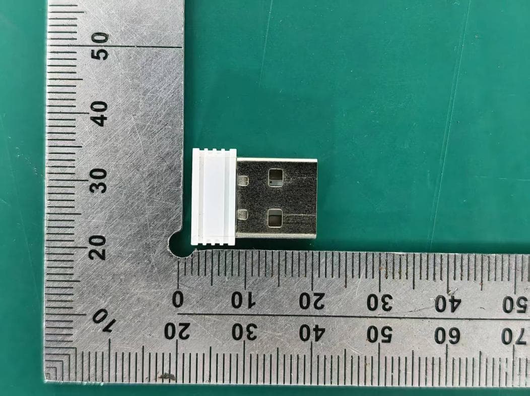
PRDRX12
May 27, 2026Wireless Receiver
Equipment Class
DXX - Part 15 Low Power Communication Device Transmitter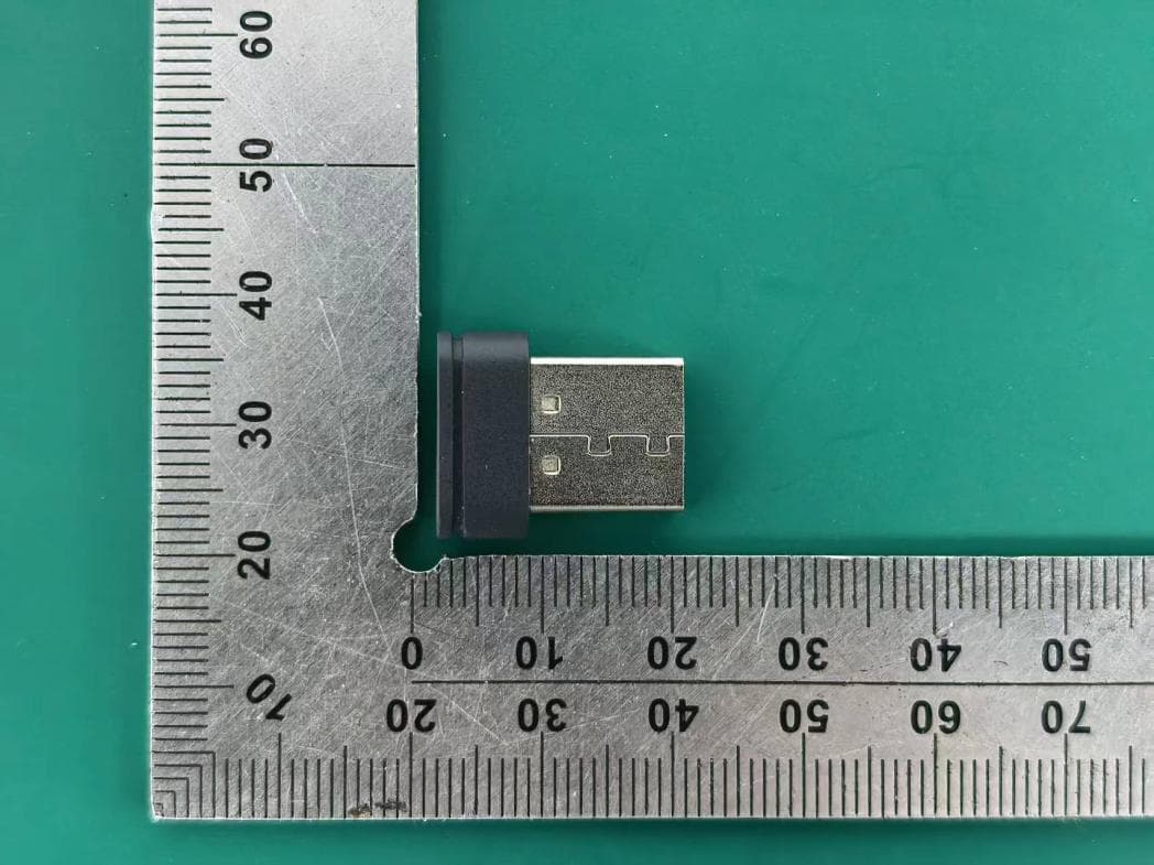
PRDRX11
Apr 07, 2026Wireless Receiver
Equipment Class
DXX - Part 15 Low Power Communication Device Transmitter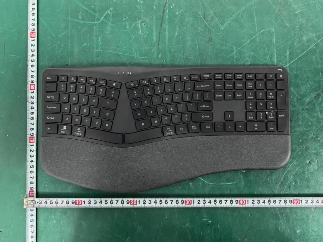
PRDKB72
Apr 03, 2026WIRELESS SPLIT KEY ERGONOMIC KEYBOARD
Equipment Class
DTS - Digital Transmission System
PRDRX1P
Apr 03, 2026Wireless Receiver
Equipment Class
DXX - Part 15 Low Power Communication Device Transmitter
PRDKB73
Apr 03, 2026Gaming Keyboard
Equipment Class
DTS - Digital Transmission System