PRDMU0010340Wireless Mouse
Acrox Technologies Co., Ltd.
Click to zoom
Application Details
- Equipment Class
- DXX - Part 15 Low Power Communication Device Transmitter
- Date of Grant
- Jun 29, 2003
- Application Purpose
- Original Equipment
- Date of Application
- Jun 29, 2003
- Equipment Note
- Wireless Mouse
- Frequency Range
- 27.04500000 - 27.14500000
- Company
- Acrox Technologies Co., Ltd.
- Country
- Taiwan
Documents & Files
Document Text
Text extracted from the exhibit documents filed with the FCC. Open a document above to read the original.
Users Manual
Troubleshooting Troubleshooting Mouse does not work upon installation Try one or more of the following: l For optimal performance, place the receiver at least eight inches or 20 centimeters away from the mouse or other electrical devices, such as the computer, the computer monitor, or external drive. l Make sure you have installed the batteries correctly. l Check the Channel Switch on both Mouse and Receiver is set to the same channel No ( for 2 Channel Model Only).. l If you are working on a metallic surface, try using a mouse pad and turning the receiver on its side for better reception Cordless 3D Optical Wheel Mouse With Advanced Human Body Detect Technology USER'S GUIDE Mouse Not Detected When using the mouse, it may not be detected by the computer, To remedy this problem, try the following l Make sure the receiver cable is plugged into the right mouse port. l Make sure your mouse port has the proper configuration. Refer to your computer documentation for the correct port configuration. l You may have other system devices(eg. a LAN card) that conflict with your mouse. Check the IRQ/address settings of these devices for conflicts, and change the settings as required. The Screen Cursors Does Not Move Properly l Change the position of your radio receiver, because it may be too far from the mouse; or the computer monitor, or a large metal object may be interfering with the receiver's radio reception. Try moving the receiver and/or mouse to improve reception. l Make sure that the battery indicator is NOT lit on. Replace batteries if the low battery indicator is lit on. l You may also need to change the channel / ID for the mouse, Press the Connect button on the receiver, then press the Connect button on the mouse. l If your tabletop surface is red in color or is highly reflective like a mirror, your tabletop surface may be interfering with the optical sensor of the mouse, Try using a mouse pad, or use the mouse on a different tabletop surface. l If you had stop to operate the mouse for a while, the Mouse maybe in Suspend Mode. To wake up the mouse, please press anyone key on the mouse. CAUTION To use this mouse properly, please read the user's guide before installation 6 For 1 Ch, 256 ID and 2 Ch, 256 ID Models FCC Compliance and Advisory Statement Federal Communications Commission (FCC) Notice This device complies with Part 15 of the FCC rules. Operation is subject to the following two conditions (1) This device may not cause harmful interference, and (2) This device must accept any interference received, including interference that may cause undesired operation. This equipment has been tested and found to comply with the limits of a Class B digital device, pursuant to Part 15 of the FCC Rules These limits are designed to provide reasonable protection against harmful interference in a residential installation This equipment generates, uses and can radiate radio frequency energy and, if not installed and used in accordance with the instructions, may cause harmful interference to radio communications, However, there is no guarantee that interference will not occur in particular installations If this equipment does cause harmful interference to radio or television reception, which can be determined by turning the equipment off and on, the user is encouraged to try to correct the interference by one or more of the following measures : 1. Reorient / Relocate the receiving antenna. 2. Increase the distance between the mouse and receiver. 3. Connect the equipment into an outlet on a circuit different from that the receiver is connected. 4. Consult the dealer or an experienced radio /TV technician for help CAUTION: Change or modifications not expressly approved by the manufacturer responsible for compliance could void the user's authority to operate the equipment Using your cordless mouse 5 Universal Scroll Provide the scrolling movement by mouse scroll button. Choose the “ Universal Scroll “ to adjust the horizontal and Vertical Movement speed by “ Slow-Fast bar “ on the window. Zoom It allow you to a certain pan area by input the numbers in “ Zoomed Size “ from 2 X 2 to 64 X 48 . And, enlarge the content of the pan area by inputting the factor number from2 to 8 times to” Zoom Factor “. Application Switching Choose this function for easy-to-do application change by clicking scroll button. Launch Default Browser Mark this function to get the path to access the IE and Netscape application by pressing the scroll button. Launch Default E-Mail Mark this function to get the path to access the E-Mail application by pressing the scroll button. Auto Scroll Give a fixed movement speed for horizontal and Vertical scrolling. Wheel Cooperate Function Control ( Office Zoom ) Holding the “ Ctrl “ Key of the keyboard by each pressing down the scroll button. Shift Holding the “ Shift “ Key of the keyboard by each pressing down the scroll button. Switch to Horizontal Wheel Choose to change the Vertical Scrolling wheel mode to Horizontal Scroll mode by each pressing down the scroll button. IE Switching Backward Choose to replace the “ Back “ function by each pressing down the scroll button. Forward Choose to replace the “ Forward “ function by each pressing down the scroll button. K.B. Simulation Choose to simulate the function key of the keyboard (F1~F10, Esc, Backspace, Enter,... ect.) by each pressing down the scroll button. Button Setting : You can set the button 3~5 by selecting the functions you want in the task. And the functions you can select are including the system frequently functions and special powerful functions as below : Mouse Utility Getting Ready Welcome Your mouse uses a newly developed optical sensor that replaces the traditional mouse ball and uses radio technology to communicate with your computer. The optical sensor accurately scans the surface of your desktop many times per second for smooth and fast cursor tracking on your computer screen. And the digital radio technology does not requi…
Text truncated - open the document above for the full version.
External Photos
C&C Laboratory Co. Ltd. REPORT NO: 03E1015-D FCC ID: PRDMU0010340 DATE: 06/17/2003 Page 20 Rev. 00 Front View of TX Back View of TX
ID Label/Location Info
FCC ID LABEL FORMAT AND LOCATION Applicant: ACROX TECHNOLOGIES CO., LTD. FCC ID: PRDMU0010340 FCC ID: PRDMU0010340 This device complies with part 15 of the FCC Rules. Operation is subject to the following two conditions: (1) This device may not cause harmful interference, and (2) this device must accept any interference received, including interference that may cause undesired operation. FCC ID LABEL AREA
Internal Photos
C&C Laboratory Co. Ltd. REPORT NO: 03E1015-D FCC ID: PRDMU0010340 DATE: 06/17/2003 Page 21 Rev. 00 Internal of TX– Open Internal of TX– 1 C&C Laboratory Co. Ltd. REPORT NO: 03E1015-D FCC ID: PRDMU0010340 DATE: 06/17/2003 Page 22 Rev. 00 Internal of TX– 2 Internal of TX– 3 C&C Laboratory Co. Ltd. REPORT NO: 03E1015-D FCC ID: PRDMU0010340 DATE: 06/17/2003 Page 23 Rev. 00 Internal of TX– 4 Internal of TX– 5 C&C Laboratory Co. Ltd. REPORT NO: 03E1015-D FCC ID: PRDMU0010340 DATE: 06/17/2003 Page 24 Rev. 00 Internal of TX– 6
Test Report
C&C Laboratory Co. Ltd. REPORT NO: 03E1015-D FCC ID: PRDMU0010340 DATE: 06/17/2003 Page 1 of 24 Rev. 00 ELECTROMAGNETIC EMISSIONS COMPLIANCE REPORT INTENTIONAL RADIATOR CERTIFICATION TO FCC PART 15 SUBPART C REQUIREMENT OF 27MHz Wireless Mouse Transmitter MODEL No.: MUF BRAND NAME: ACROX FCC ID: PRDMU0010340 REPORT NO: 03E1015-D ISSUE DATE: June 17, 2003 Prepared for ACROX TECHNOLOGIES CO., LTD. 8F, NO. 437, RUI GUANG RD., NEI HU DIST.,TAIPEI 114, TAIWAN, R. O. C. Prepared by C&C LABORATORY, CO., LTD. No. 163-1, Chung Sheng Road, Hsin Tien City, Taipei, Taiwan, R. O. C. TEL: (02)2217-0894 FAX: (02)2217-1029 Lab. Code: 200617-0 C&C Laboratory Co. Ltd. REPORT NO: 03E1015-D FCC ID: PRDMU0010340 DATE: 06/17/2003 Page 2 Rev. 00 VERIFICATION OF COMPLIANCE Applicant: ACROX TECHNOLOGIES CO., LTD. 8F, NO. 437, RUI GUANG RD., NEI HU DIST., TAIPEI 114, TAIWAN, R. O. C. Product Description: 27MHz Wireless Mouse Transmitter Brand Name: ACROX Model No.: MUF Serial Number: N/A File Number: 03E1015-D Date of test: May 15, 2003 & May 19, 2003 We hereby certify that: The above equipment was tested by C&C Laboratory Co., Ltd. The test data, data evaluation, test procedures, and equipment configurations shown in this report were made in accordance with the procedures given in ANSI C63.4 (1992) and the energy emitted by the sample EUT tested as described in this report is in compliance with conducted and radiated emission limits of FCC Rules Part 15.227 The test results of this report relate only to the tested sample identified in this report. Authorized Signatory C&C Laboratory Co. Ltd. REPORT NO: 03E1015-D FCC ID: PRDMU0010340 DATE: 06/17/2003 Page 3 Rev. 00 Table of Contents 1. GENERAL INFORMATION................................................................................................4 1.1 PRODUCT DESCRIPTION..............................................................................................................4 1.2 RELATED SUBMITTAL(S) / GRANT (S)...........................................................................................4 1.3 TEST METHODOLOGY.................................................................................................................4 1.4 TEST FACILITY...........................................................................................................................4 2. SYSTEM TEST CONFIGURATION....................................................................................5 2.1 EUT CONFIGURATION................................................................................................................5 2.2 EUT EXERCISE...........................................................................................................................5 2.3 TEST PROCEDURE.......................................................................................................................5 2.4 LIMITATION................................................................................................................................5 2.5 CONFIGURATION OF TESTED SYSTEM...........................................................................................7 3. SUMMARY OF TEST RESULTS.........................................................................................8 4. DESCRIPTION OF TEST MODES......................................................................................8 5. CONDUCTED EMISSIONS TEST (NOT APPLICABLE IN THIS REPORT).............9 5.1 MEASUREMENT PROCEDURE:......................................................................................................9 5.2 TEST SET-UP (BLOCK DIAGRAM OF CONFIGURATION).................................................................9 5.3 MEASUREMENT EQUIPMENT USED:..............................................................................................9 5.4 MEASUREMENT RESULT:.............................................................................................................9 5.5 CONDUCTED MEASUREMENT PHOTOS:.........................................................................................9 6. RADIATED EMISSION TEST............................................................................................10 6.1 MEASUREMENT PROCEDURE......................................................................................................10 6.2 TEST SET-UP (BLOCK DIAGRAM OF CONFIGURATION)................................................................11 6.3 M EASUREMENT E QUIPMENT U SED :.............................................................................................12 6.4 FIELD STRENGTH CALCULATION.................................................................................................12 6.5 MEASUREMENT RESULT.............................................................................................................13 6.6 MEASUREMENT RESULT.............................................................................................................14 7. OCCUPIED BANDWIDTH.................................................................................................15 7.1 MEASUREMENT PROCEDURE......................................................................................................15 7.2 TEST SET-UP (BLOCK DIAGRAM OF CONFIGURATION)................................................................15 7.3 MEASUREMENT EQUIPMENT USED:.............................................................................................15 7.4 MEASUREMENT RESULTS:...........................................................................................................15 PHOTOGRAPHS OF SET UP............................................................................................................17 PHOTOGRAPHS OF EUT.................................................................................................................19 C&C Laboratory Co. Ltd. REPORT NO: 03E1015-D FCC ID: PRDMU0010340 DATE: 06/17/2003 Page 4 Rev. 00 1. GENERAL INFORMATION 1.1 Prod…
Text truncated - open the document above for the full version.
Test Setup Photos
C&C Laboratory Co. Ltd. REPORT NO: 03E1015-D FCC ID: PRDMU0010340 DATE: 06/17/2003 Page 18 Rev. 00 Radiated Emission Setup Photos
Contact Information
Applicant
Gavin Hsieh(Product Manager)
Test Firm
Compliance Certification Services Inc.Kurt Chen
Technical Specifications
| # | Rule Parts | Frequency Range | Power Output |
|---|---|---|---|
| 1 | 15C | 27.045 MHz - 27.145 MHz | - |
Other Applications from Acrox Technologies Co., Ltd.
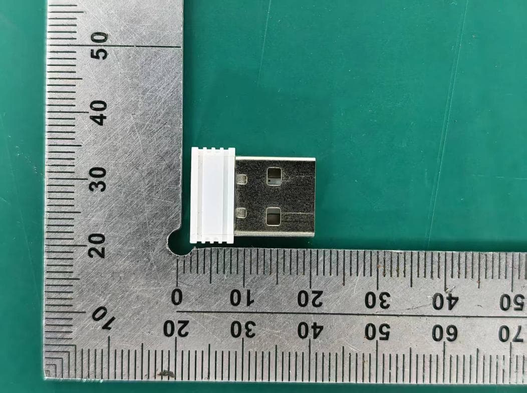
PRDRX12
May 27, 2026Wireless Receiver
Equipment Class
DXX - Part 15 Low Power Communication Device Transmitter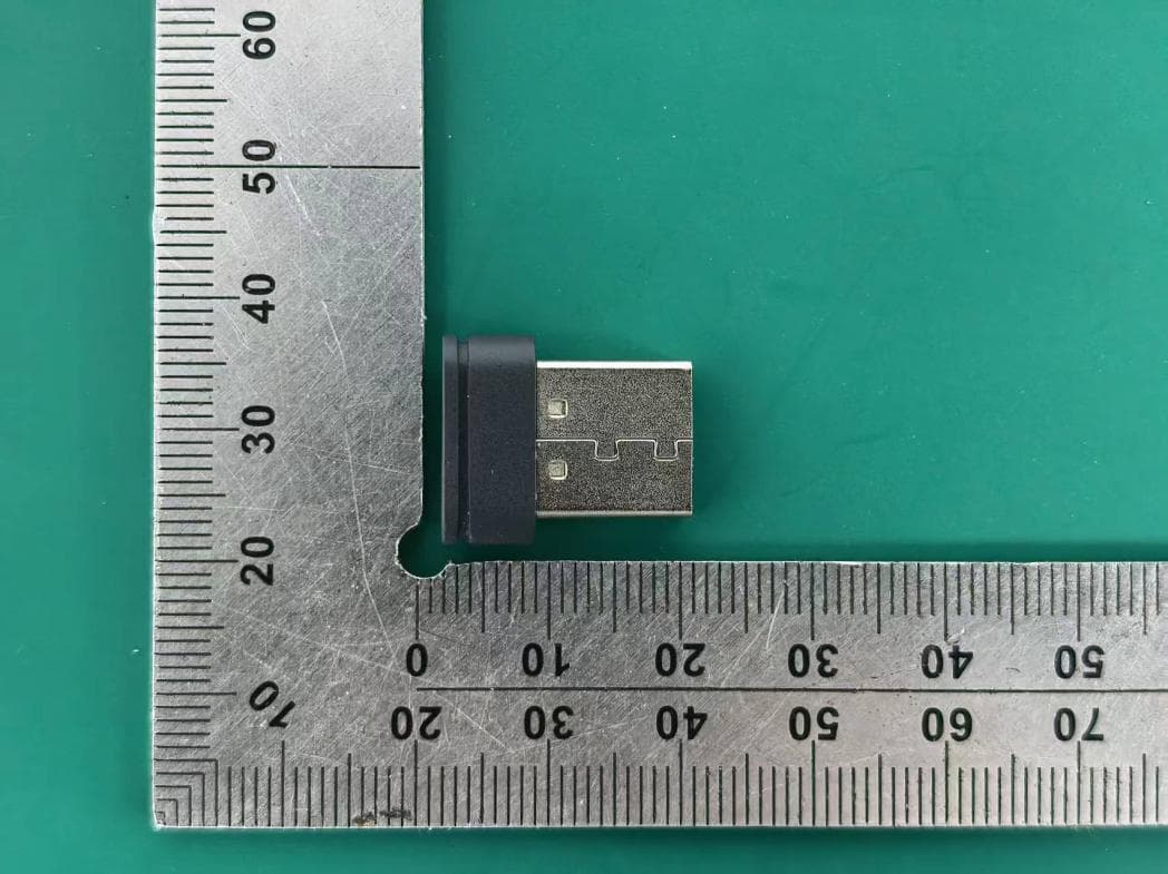
PRDRX11
Apr 07, 2026Wireless Receiver
Equipment Class
DXX - Part 15 Low Power Communication Device Transmitter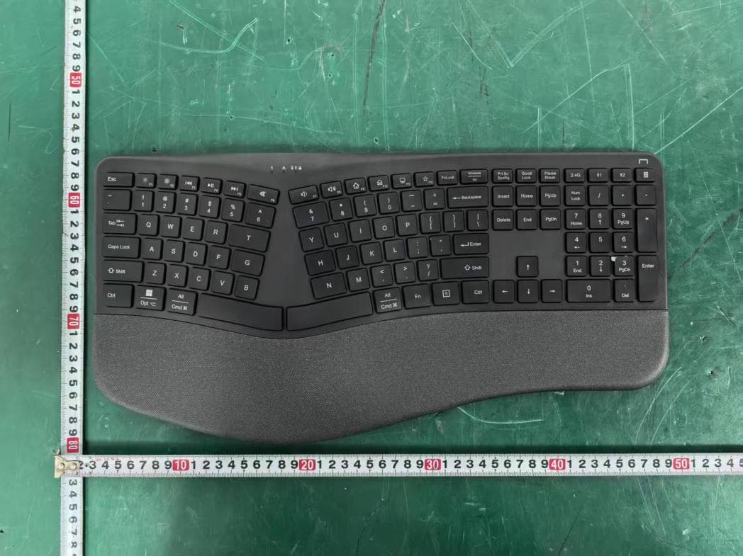
PRDKB72
Apr 03, 2026WIRELESS SPLIT KEY ERGONOMIC KEYBOARD
Equipment Class
DTS - Digital Transmission System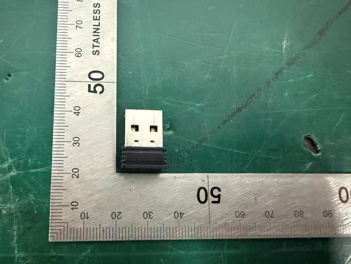
PRDRX1P
Apr 03, 2026Wireless Receiver
Equipment Class
DXX - Part 15 Low Power Communication Device Transmitter
PRDKB73
Apr 03, 2026Gaming Keyboard
Equipment Class
DTS - Digital Transmission System