PRDMU02Bluetooth Optical Mouse
Acrox Technologies Co., Ltd.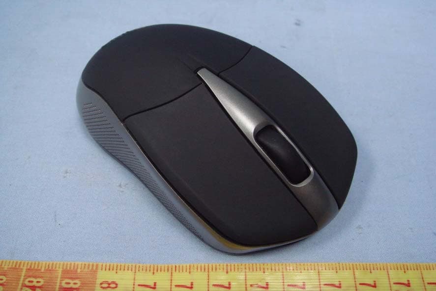
Click to zoom
Application Details
- Equipment Class
- DSS - Part 15 Spread Spectrum Transmitter
- Date of Grant
- Apr 13, 2011
- Application Purpose
- Original Equipment
- Date of Application
- Apr 13, 2011
- Equipment Note
- Bluetooth Optical Mouse
- Frequency Range
- 2402.00000000 - 2480.00000000
- Company
- Acrox Technologies Co., Ltd.
- Country
- Taiwan
Documents & Files
Document Text
Text extracted from the exhibit documents filed with the FCC. Open a document above to read the original.
Users Manual
Bluetooth Optical Mouse OWNER'S GUIDE Ver.1.0 1 Federal Communication Commission Interference Statement This equipment has been tested and found to comply with the limits for a Class B digital device, pursuant to Part 15 of the FCC Rules. These limits are designed to provide reasonable protection against harmful interference in a residential installation. This equipment generates, uses and can radiate radio frequency energy and, if not installed and used in accordance with the instructions, may cause harmful interference to radio communications. However, there is no guarantee that interference will not occur in a particular installation. If this equipment does cause harmful interference to radio or television reception, which can be determined by turning the equipment off and on, the user is encouraged to try to correct the interference by one of the following measures: - Reorient or relocate the receiving antenna. - Increase the separation between the equipment and receiver. - Connect the equipment into an outlet on a circuit different from that to which the receiver is connected. - Consult the dealer or an experienced radio/TV technician for help. FCC Caution: Any changes or modifications not expressly approved by the party responsible for compliance could void the user's authority to operate this equipment. This device complies with Part 15 of the FCC Rules. Operation is subject to the following two conditions: (1) This device may not cause harmful interference, and (2) this device must accept any interference received, including interference that may cause undesired operation. Per FCC 15.21, you are cautioned that changes or modifications not expressly approved by the part responsible for compliance could void the user’s authority to operate the equipment. FCC RF Radiation Exposure Statement: This equipment complies with FCC RF radiation exposure limits set forth for an uncontrolled environment. This device and its antenna must not be co-located or operating in conjunction with any other antenna or transmitter. 2 Functional Introduction Mouse Wheel & Pairing LED Battery Cover Connect Button ON / OFF Switch LED Blinking Paired Link LED OFF Connected OK 3 Battery and Power Management: Installing the batteries Step 1: Pull the battery cover backward. Step 2: Insert the batteries as shown inside the battery compartment. Step 3: Replace the cover. Power saving features: To conserve the battery power, the mouse offers power management functions as below: 1. The mouse goes into “Saving Mode” after 30 seconds of inactivity. 2. The mouse powers down to “Sleep Mode” after 10 minutes of Inactivity. Press one of the mouse buttons to wake it up while in Sleep Mode. There may be a slight delay while the mouse re-establishes Bluetooth connection from power saving or sleep mode. Push 4 Establishing a Bluetooth Connection The Bluetooth mouse can work in any Bluetooth working environment. Before connecting your Bluetooth mouse with your computer, make sure your computer has a working Bluetooth configuration that meets Bluetooth Specification v1.1 or higher with Human Interface Device (HID) profile. If your computer does not support Bluetooth, you need to obtain and install a commercially available Bluetooth adapter which converts your computer to a Bluetooth environment. Paring your Bluetooth mouse with your computer Before paring your Bluetooth mouse with your computer, you should read through the instructions that came with your Bluetooth hardware and software for detail how to pair a device to your specific Bluetooth configuration. Follow below steps to pair your Bluetooth mouse under Windows XP/SP2 system. 1. Attach or turn on the Bluetooth radio adaptor for your Windows XP computer. 2. Switch on the mouse. 3. Click Start menu, click Control Panel and double click “Bluetooth Devices” . 4. On the “Devices” tab, click “Add” . 5 5. Select the “My device is set up and ready to be found” check box, and then click “Next” . 6. Press the connection button of the mouse and it starts paring with your PC/notebook. The Green LED light will blink when connecting. Click the icon that represents the Bluetooth mouse, and then click “Next” . 6 7. Click “Don’t use a passkey” , and then click “Next” . Check the documentation for the mouse for any passkey instructions. 8. You can find the Bluetooth mouse in the “Devices” tab when it connected. The Green LED will turn off automatically when the paring is successfully done. Note : Once the Bluetooth mouse is installed, you can either disconnect the wired mouse or leave it connected. (If you leave both mice connected, they will both work.) 7 Disconnecting Bluetooth mouse from your computer If you would like to disconnect your Bluetooth mouse, just open the Bluetooth devices control panel and delete the pairing for the mouse. 8 Troubleshooting A. Mouse does not work upon installation or is not detected Try one or more of the following: y Make sure you have installed the batteries correctly and turn the switch on. Replace a fresh set of batteries if it still doesn’t work. y Make sure that computer’s Bluetooth is enabled. y Press the connection button to reset the Bluetooth connection between your mouse and computer. Make sure it had been detected by the Operating Systems properly. B. The screen cursor does not move properly If your screen cursor lags behind the movement, then your Bluetooth connection may not be able to transmit all of the data from the mouse with the necessary speed. This may be caused by interference from other radio sources, obstructions in the radio wave path, excessive distance from the computer, or a combination of the above. Try the following actions to improve your Bluetooth connection and optimize your mouse performance: y Remove any metallic objects from the line of sight between your computer and Bluetooth mouse. y If you are using a computer with a built-in Bluetooth antenna, try reorienting the computer until you get a better data rate. y If …
Text truncated - open the document above for the full version.
Attestation Statements
BLUETOOTH DECLARATION PER FCC 15.247 REQUIREMENTS 1 Output power and channel separation of a Bluetooth device in the different operating modes: The different operating modes (data-mode, acquisition-mode) of a Bluetooth device don’t influence the output power and the channel spacing. There is only one transmitter which is driven by identical input parameters concerning these two parameters. Only a different hopping sequence will be used. For this reason the check of these RF parameters in one op-mode is sufficient. 2 Frequency range of a Bluetooth device: Hereby we declare that the maximum frequency of this device is: 2402 – 2480 MHz (Data Rate: 1Mbps). This is according the Bluetooth Core Specification V 1.0B (+ critical errata) for devices which will be operated in the USA. This was checked during the Bluetooth Qualification tests (Test Case: TRM/CA/04-E). Other frequency ranges ( e.g. for Spain, France, Japan) which are allowed according the Core Specification are not supported by this device. 3 Co-ordination of the hopping sequence in data mode to avoid simultaneous occupancy by multiple transmitters: Bluetooth units which want to communicate with other units must be organized in a structure called piconet. This piconet consist of max. 8 Bluetooth units. One unit is the master the other seven are the slaves. The master co-ordinates frequency occupation in this piconet for all units. As the master hop sequence is derived from it’s BD address which is unique for every Bluetooth device, additional masters intending to establish new piconets will always use different hop sequences. 4 Example of a hopping sequence in data mode: Example of a 79 hopping sequence in data mode: 40, 21, 44, 23, 42, 53, 46, 55, 48, 33, 52, 35, 50, 65, 54, 67, 56, 37, 60, 39, 58, 69, 62, 71, 64, 25, 68, 27, 66, 57, 70, 59, 72, 29, 76, 31, 74, 61, 78, 63, 01, 41, 05, 43, 03, 73, 07, 75, 09, 45, 13, 47, 11, 77, 15, 00, 64, 49, 66, 53, 68, 02, 70, 06, 01, 51, 03, 55, 05, 04 5 Equally average use of frequencies in data mode and behaviour for short transmissions: The generation of the hopping sequence in connection mode depends essentially on two input values: 1. LAP/UAP of the master of the connection 2. Internal master clock The LAP (lower address part) are the 24 LSB’s of the 48 BD_ADDRESS. The BD_ADDRESS is an unambiguous number of every Bluetooth unit. The UAP (upper address part) are the 24 MSB’s of the 48 BD_ADDRESS. The internal clock of a Bluetooth unit is derived from a free running clock which is never adjusted and is never turned off. For synchronisation with other units only offset are used. It has no relation to the time of the day. Its resolution is at least half the RX/TX slot length of 312.5 μs. The clock has a cycle of about one day (23h30). In most case it is implemented as 28 bit counter. For the deriving of the hopping sequence the entire LAP (24 bits), 4 LSB’s (4 bits) (Input 1) and the 27 MSB’s of the clock (Input 2) are used. With this input values different mathematical procedures (permutations, additions, XOR-operations) are performed to generate the sequence. This will be done at the beginning of every new transmission. Regarding short transmissions the Bluetooth system has the following behaviors: The first connection between the two devices is established, a hopping sequence was generated. For transmitting the wanted data the complete hopping sequence was not used. The connection ended. The second connection will be established. A new hopping sequence is generated. Due to the fact that the Bluetooth clock has a different value, because the period between the two transmission is longer (and it cannot be shorter) than the minimum resolution of the clock (312.5 μs). The hopping sequence will always differ from the first one. 6 Receiver input bandwidth and behaviors for repeated single or multiple packets: The input bandwidth of the receiver is 1 MHz. In every connection one Bluetooth device is the master and the other one is the slave. The master determines the hopping sequence (see chapter 5). The slave follows this sequence. Both devices shift between RX and TX time slot according to the clock of the master. Additionally the type of connection (e.g. single or multislot packet) is set up at the beginning of the connection. The master adapts its hopping frequency and its TX/RX timing according to the packet type of the connection. Also the slave of the connection will use these settings. Repeating of a packet has no influence on the hopping sequence. The hopping sequence generated by the master of the connection will be followed in any case. That means, a repeated packet will not be send on the same frequency, it is send on the next frequency of the hopping sequence. 7 Dwell time in data mode The dwell time of 0.3797s within a 30 second period in data mode is independent from the packet type (packet length). The calculation for a 30 second period is a follows: Dwell time = time slot length * hop rate / number of hopping channels *30s Example for a DH1 packet (with a maximum length of one time slot) Dwell time = 625 μs * 1600 1/s / 79 * 30s = 0.3797s (in a 30s period) For multislot packet the hopping is reduced according to the length of the packet. Example for a DH5 packet (with a maximum length of five time slots) Dwell time = 5 * 625 μs * 1600 * 1/5 *1/s / 79 * 30s = 0.3797s (in a 30s period) This is according the Bluetooth Core Specification V 1.0B (+ critical errata) for all Bluetooth devices. There for all Bluetooth devices comply with the FCC dwell time requirement in data mode. This was checked during the Bluetooth Qualification tests. The Dwell time in hybrid mode is measured and stated in the test report. 8 Channel Separation in hybrid mode The nominal channel spacing of the Bluetooth system is 1Mhz independent of the operating mode. The maximum “initial carrier frequency tolerance” which is allowed for Bluetooth is fcenter = 75 kHz. This was checked during the Bluetooth Qualificatio…
Text truncated - open the document above for the full version.
Cover Letter(s)
Acrox Technologies Co., Ltd. Date: March 16, 2011 Federal Communications Commission Authorization and Evaluation Division FCC IDPRDMU02 Confidentiality Request Pursuant to Sections 0.457 and 0.459 of the Commission’s Rules, the applicant hereby requests confidential treatment of information applied this application as outlined below: 1. Block Diagram 2. Schematics 3. Operational Description The above materials contain trade secrets and proprietary information not customarily released to the public. The public disclosure of these matters might be harmful to the applicant and provide unjustified benefits to its competitors. The Applicant understands that pursuant to Rule 0.457, disclosure of this Application and all accompanying documentation will not be made before the date of the Grant for this application
Cover Letter(s)
Acrox Technologies Co., Ltd. Date: March 16, 2011 Dear Sir, I hereby have entrusted the following person to be a proxy regarding application for Type Certification. Compliance Certification Services Inc. Address: No. 11, Wugong 6 th Rd., Wugu Towership, Taipei County 24891, Taiwan Mr. Rex Lai Job Title: Section Manager Email: [email protected] I am therefore responsible for the contents of the application. Brand Name and Model Name of the specified radio equipment: Model Name: B12 Brand Name: ACROX FCC ID: PRDMU02 Product Name: Bluetooth Optical Mouse
External Photos
Report No: T110303201 Page 1 / 5 Rev.00 EXTERNAL PHOTOGRAPHS OF EUT Report No: T110303201 Page 2 Rev.00
Internal Photos
Report No: T110303201 Page 3 Rev.00 INTERNAL PHOTOGRAPHS OF EUT Report No: T110303201 Page 4 Rev.00 Antenna Report No: T110303201 Page 5 Rev.00
Parts List/Tune Up Info
Antenna Specification Date:March 31, 2011 Antenna Type: PCB Antenna Antenna Gain: -1.55dBi
Test Report
Report No: T110303201-RP1 FCC ID: PRDMU02 Date of Issue: March 22, 2011 Page 1 / 53 Rev.00 FCC 47 CFR PART 15 SUBPART C TEST REPORT For Bluetooth Optical Mouse Model: B12 Trade Name: Acrox; TARGUS Issued to Acrox Technologies Co., Ltd. 4F, No. 89, Min shan St., Nei hu Dist., Taipei City 114, Taiwan, R.O.C. Issued by Compliance Certification Services Inc. No.81-1, Lane 210, Bade 2nd Rd., Lujhu Township, Taoyuan County 33841,Taiwan, R.O.C. TEL: 886-3-324-0332 FAX: 886-3-324-5235 http://www.ccsrf.com [email protected] Note: This report shall not be reproduced except in full, without the written approval of Compliance Certification Services Inc. This document may be altered or revised by Compliance Certification Services Inc. personnel only, and shall be noted in the revision section of the document. The client should not use it to claim product endorsement by TAF, A2LA, NIST or any government agencies. The test results in the report only apply to the tested sample. Report No: T110303201-RP1 FCC ID: PRDMU02 Date of Issue: March 22, 2011 Page 2 Rev.00 This report shall not be reproduced except in full, without the written approval of Compliance Certification Services. Revision History Rev. Issue Date Revisions Effect Page Revised By 00 March 22, 2011 Initial Issue ALL Jill Shiau Report No: T110303201-RP1 FCC ID: PRDMU02 Date of Issue: March 22, 2011 Page 3 Rev.00 This report shall not be reproduced except in full, without the written approval of Compliance Certification Services. TABLE OF CONTENTS 1 TEST RESULT CERTIFICATION........................................................................................... 4 2 EUT DESCRIPTION ............................................................................................................... 5 3 TEST METHODOLOGY ......................................................................................................... 6 3.1. EUT CONFIGURATION .................................................................................................... 6 3.2. EUT EXERCISE ................................................................................................................ 6 3.3. GENERAL TEST PROCEDURES ..................................................................................... 6 3.4. FCC PART 15.205 RESTRICTED BANDS OF OPERATIONS ......................................... 7 3.5. DESCRIPTION OF TEST MODES .................................................................................... 8 4 INSTRUMENT CALIBRATION............................................................................................... 9 4.1. MEASUREMENT EQUIPMENT USED ............................................................................. 9 4.2. MEASUREMENT UNCERTAINTY .................................................................................. 10 5 FACILITIES AND ACCREDITATIONS................................................................................. 11 5.1. FACILITIES...................................................................................................................... 11 5.2. EQUIPMENT ................................................................................................................... 11 5.3. TABLE OF ACCREDITATIONS AND LISTINGS............................................................. 12 6 SETUP OF EQUIPMENT UNDER TEST.............................................................................. 13 6.1. SETUP CONFIGURATION OF EUT ............................................................................... 13 6.2. SUPPORT EQUIPMENT ................................................................................................. 13 7 FCC PART 15.247 REQUIREMENTS .................................................................................. 14 7.1. 20DB BANDWIDTH ......................................................................................................... 14 7.2. PEAK POWER................................................................................................................. 17 7.3. AVERAGE POWER ......................................................................................................... 18 7.4. BAND EDGES MEASUREMENT .................................................................................... 19 7.5. FREQUENCY SEPARATION .......................................................................................... 24 7.6. NUMBER OF HOPPING FREQUENCY .......................................................................... 26 7.7. TIME OF OCCUPANCY (DWELL TIME) ......................................................................... 28 7.8. SPURIOUS EMISSIONS ................................................................................................. 39 7.9. POWERLINE CONDUCTED EMISSIONS ...................................................................... 49 8 RADIO FREQUENCY EXPOSURE ...................................................................................... 50 9 PHOTOGRAPHS OF TEST SETUP..................................................................................... 51 Report No: T110303201-RP1 FCC ID: PRDMU02 Date of Issue: March 22, 2011 Page 4 Rev.00 This report shall not be reproduced except in full, without the written approval of Compliance Certification Services. 1 TEST RESULT CERTIFICATION Applicant: Acrox Technologies Co., Ltd. 4F, No. 89, Min shan St., Nei hu Dist., Taipei City 114, Taiwan, R.O.C Equipment Under Test: Bluetooth Optical Mouse Trade Name: Acrox; TARGUS Model: B12 Date of Test: March 14 ~ 17, 2011 APPLICABLE STANDARDS STANDARD TEST RESULT FCC 47 CFR Part 15 Subpart C No non-compliance noted We hereby certify that: The above equipment was tested by Compliance Certification Services Inc. The test data, data evaluation, test procedures, and equipment configurations shown in this report were made in accordance with the procedures given in ANSI C63.4: 2009 and the energy emitted by the sample EUT tested as described in…
Text truncated - open the document above for the full version.
Test Setup Photos
Report No: T110303201-RP1 FCC ID: PRDMU02 Date of Issue: March 22, 2011 Page 52 Rev.00 This report shall not be reproduced except in full, without the written approval of Compliance Certification Services. 9 PHOTOGRAPHS OF TEST SETUP Conducted Emission Setup Photo Report No: T110303201-RP1 FCC ID: PRDMU02 Date of Issue: March 22, 2011 Page 53 Rev.00 This report shall not be reproduced except in full, without the written approval of Compliance Certification Services. Radiated Emission Setup Photos 30 ~ 1000MHz Report No: T110303201-RP1 FCC ID: PRDMU02 Date of Issue: March 22, 2011 Page 54 Rev.00 This report shall not be reproduced except in full, without the written approval of Compliance Certification Services. Above 1GHz
Contact Information
Applicant
Gavin Hsieh(Product Manager)
Test Firm
Compliance Certification Services Inc.Kurt Chen
Technical Specifications
| # | Rule Parts | Frequency Range | Power Output |
|---|---|---|---|
| 1 | 15C | 2.40 GHz - 2.48 GHz | 1.05 mW |
Other Applications from Acrox Technologies Co., Ltd.
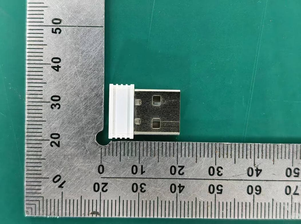
PRDRX12
May 27, 2026Wireless Receiver
Equipment Class
DXX - Part 15 Low Power Communication Device Transmitter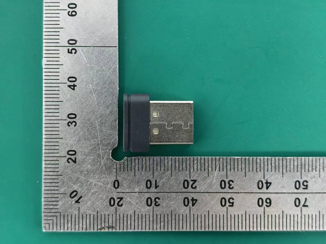
PRDRX11
Apr 07, 2026Wireless Receiver
Equipment Class
DXX - Part 15 Low Power Communication Device Transmitter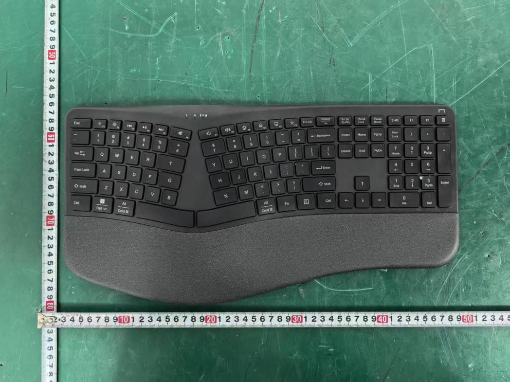
PRDKB72
Apr 03, 2026WIRELESS SPLIT KEY ERGONOMIC KEYBOARD
Equipment Class
DTS - Digital Transmission System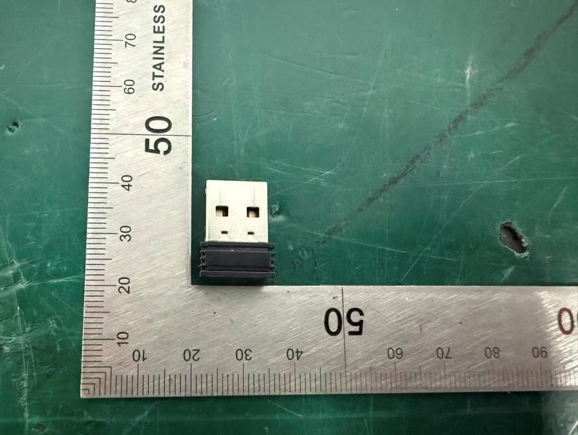
PRDRX1P
Apr 03, 2026Wireless Receiver
Equipment Class
DXX - Part 15 Low Power Communication Device Transmitter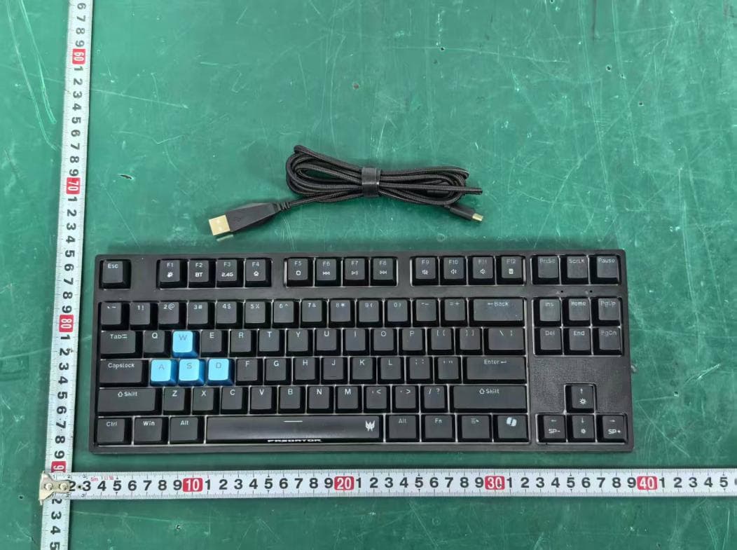
PRDKB73
Apr 03, 2026Gaming Keyboard
Equipment Class
DTS - Digital Transmission System