PRDMU35WIRELESS MOUSE
Acrox Technologies Co., Ltd.Application Details
- Equipment Class
- DXT - Part 15 Low Power Transceiver, Rx Verified
- Date of Grant
- May 31, 2015
- Application Purpose
- Original Equipment
- Date of Application
- May 30, 2015
- Equipment Note
- WIRELESS MOUSE
- Frequency Range
- 2404.00000000 - 2478.00000000
- Company
- Acrox Technologies Co., Ltd.
- Country
- Taiwan
Documents & Files
Document Text
Text extracted from the exhibit documents filed with the FCC. Open a document above to read the original.
Users Manual
2.4GHz Wireless Ergo Optical Mouse w/Nano Receiver USER'S GUIDE Ver.:1.00 CAUTION: To use this product properly, please read the user's guide before installing. 1 Federal Communication Commission Interference Statement This equipment has been tested and found to comply with the limits for a Class B digital device, pursuant to Part 15 of the FCC Rules. These limits are designed to provide reasonable protection against harmful interference in a residential installation. This equipment generates, uses and can radiate radio frequency energy and, if not installed and used in accordance with the instructions, may cause harmful interference to radio communications. However, there is no guarantee that interference will not occur in a particular installation. If this equipment does cause harmful interference to radio or television reception, which can be determined by turning the equipment off and on, the user is encouraged to try to correct the interference by one of the following measures: - Reorient or relocate the receiving antenna. - Increase the separation between the equipment and receiver. - Connect the equipment into an outlet on a circuit different from that to which the receiver is connected. - Consult the dealer or an experienced radio/TV technician for help. FCC Caution: Any changes or modifications not expressly approved by the party responsible for compliance could void the user's authority to operate this equipment. This device complies with Part 15 of the FCC Rules. Operation is subject to the following two conditions: (1) This device may not cause harmful interference, and (2) this device must accept any interference received, including interference that may cause undesired operation. 2 Functional Introduction Forward Press this button to view the next page in your Internet browser. Backward Press this button to view the previous page in your Internet browser. Installing the batteries Step 1: Take the battery cover off. Step 2: Insert the batteries as shown inside the battery compartment. Step 3: Replace the cover. Left button Right button Battery Cover Scrolling Wheel Connect Button ON/OFF Switch Nano Receiver Backward Forward 3 **Warning: *Please insert the battery with the correct position according to the instruction labeled on the mouse. Setup the Connection between the Receiver and the Mouse 1. Insert the batteries into the mouse, then follow the steps below. 2. In the meantime, to open the mouse under the cover, take the nano receiver out. AAA Battery Pull 1st 2nd 4 3. Plug the Nano receiver into the USB port on your computer. 4. If the mouse does not work, please put it into pairing mode. 5. Pairing: Re-plug the receiver into the USB port on your computer and turn on the mouse. If the mouse does not work after 10 seconds, pair them again. (The receiver has auto pairing function).
Cover Letter(s)
SCS-F18: Project and Product Certification Representative Authorization Letter Page 1 of 2 Rev 5.0 775 Montague Expressway Milpitas, CA 95035 Tel: 408-526-1188 Fax: 408-526-1088 Email: [email protected] Project and Product Certification Representative Authorization Letter Revision History Reason for Amendment (current / obsolete) From To Approved Date Initial Release (obsolete) 1.0 1.0 Nov-14-2006 Revised wording (obsolete) 1.0 2.0 Sept–25-2007 Updated company template (obsolete) 2.0 3.0 Jan-31-2012 Updated letter information (obsolete) 3.0 4.0 May-23-2014 Added FCC ID field (current) 4.0 5.0 Sept 16 2014
Cover Letter(s)
SCS-F19: Confidentiality Request Letter Page 1 of 2 Rev 3.0 775 Montague Expressway Milpitas, CA 95035 Tel: 408-526-1188 Fax: 408-526-1088 Email: [email protected] Confidentiality Request Letter Revision History Reason for Amendment (current / obsolete) From To Approved Date Initial Release (obsolete) 1.0 1.0 Nov-14-2006 Adding CFR 2.459 (obsolete) 1.0 2.0 August – 11 - 2008 Updated company template & Added text box (current) 2.0 3.0 Jan-31-2012
External Photos
Dongguan Nore Testing Center Co., Ltd. Report No.: NTC1505123F FCC ID: PRDMU35 Dongguan Nore Testing Center Co., Ltd. Report No.: NTC1505123F FCC ID: PRDMU35 Dongguan Nore Testing Center Co., Ltd. Report No.: NTC1505123F FCC ID: PRDMU35
Internal Photos
Dongguan Nore Testing Center Co., Ltd. Report No.: NTC1505123F FCC ID: PRDMU35 Dongguan Nore Testing Center Co., Ltd. Report No.: NTC1505123F FCC ID: PRDMU35 Dongguan Nore Testing Center Co., Ltd. Report No.: NTC1505123F FCC ID: PRDMU35 RF Antenna RF Chip
Test Report
Dongguan Nore Testing Center Co., Ltd. Report No.: NTC1505123F FCC ID: PRDMU35 Page 2 of 20 Table of Contents 1. GENERAL INFORMATION ................................................................................................ 3 1.1 PRODUCT DESCRIPTION FOR EQUIPMENT UNDER TEST.................................................................... 3 1.2 RELATED SUBMITTAL(S) / GRANT (S)................................................................................................ 5 1.3 TEST METHODOLOGY...................................................................................................................... 5 1.4 EQUIPMENT MODIFICATIONS............................................................................................................ 5 1.5 SUPPORT DEVICE............................................................................................................................ 5 1.6 TEST FACILITY AND LOCATION.......................................................................................................... 5 1.7 SUMMARY OF TEST RESULTS........................................................................................................... 6 2. SYSTEM TEST CONFIGURATION .................................................................................... 7 2.1 EUT CONFIGURATION...................................................................................................................... 7 2.2 SPECIAL ACCESSORIES.................................................................................................................... 7 2.3 DESCRIPTION OF TEST MODES......................................................................................................... 7 2.4 EUT EXERCISE................................................................................................................................7 3. RADIATED EMISSION TEST............................................................................................. 8 3.1 TEST SET-UP (BLOCK DIAGRAM OF CONFIGURATION)..................................................................... 8 3.2 MEASUREMENT PROCEDURE........................................................................................................... 9 3.3 LIMIT.............................................................................................................................................. 10 3.4 MEASUREMENT RESULTS ..................................................................................................... 11 4. 20DB BANDWIDTH.......................................................................................................... 15 4.1 MEASUREMENT PROCEDURE......................................................................................................... 15 4.2 TEST SET-UP (BLOCK DIAGRAM OF CONFIGURATION)................................................................... 15 4.3 MEASUREMENT RESULTS............................................................................................................... 15 5. BAND EDGE ....................................................................................................................18 5.1 MEASUREMENT PROCEDURE......................................................................................................... 18 5.2 LIMIT.............................................................................................................................................. 18 5.3 MEASUREMENT RESULTS............................................................................................................... 18 6. ANTENNA REQUIREMENT ............................................................................................. 19 6.1 MEASUREMENT PROCEDURE......................................................................................................... 19 6.2 MEASUREMENT RESULTS............................................................................................................... 19 7. TEST EQUIPMENT LIST.................................................................................................. 20 Dongguan Nore Testing Center Co., Ltd. Report No.: NTC1505123F FCC ID: PRDMU35 Page 3 of 20 1. GENERAL INFORMATION 1.1 Product Description for Equipment under Test This device is a WIRELESS MOUSE, it’s powered by 2 * 1.5V AAA battery. For more details features, please refer to User’s Manual. Manufacturer : Acrox Technologies Co., Ltd. Address : Hsinmin Industrial, Changan Town, Dongguan City, Guangdong, China Frequency range: : 2404-2478MHz Modulation : GFSK Number of Channel : 20 Antenna Type : PCB Antenna Gain : -1dBi (declaration by manufacturer) Power Supply : 2* 1.5V AAA Battery) Model name : G5L, ONB15HO201, ONB15HO202, ONB15HO203, ONB15HO204 Model Difference Description : These models have the same circuit schematic, construction and critical components except model number and appearance due to marketing purpose. Note: :N/A Dongguan Nore Testing Center Co., Ltd. Report No.: NTC1505123F FCC ID: PRDMU35 Page 4 of 20 Channel List: Note: The Lowest, middle, and the Highest frequency of channel were selected to perform the test. The frequency selected see below: The Lowest frequency: 2405MHz The middle frequency: 2441MHz The Highest frequency: 2478MHz Dongguan Nore Testing Center Co., Ltd. Report No.: NTC1505123F FCC ID: PRDMU35 Page 5 of 20 1.2 Related Submittal(s) / Grant (s) This submittal(s) (test report) is intended for FCC ID: PRDMU35 filing to comply with Section 15.249 of the FCC Part 15 (2014), Subpart C Rule. 1.3 Test Methodology Both AC mains line-conducted and radiated emission measurements were performed according to the procedures in ANSI C63.10 (2013). Radiated emission measurement was performed in semi-anechoic chamber and conducted emission measurement was performed in shield room. For radiated emission measurement, preliminary scans were performed in the semi-anechoic chamber only to determine the worst case modes. All radiate…
Text truncated - open the document above for the full version.
Test Setup Photos
Dongguan Nore Testing Center Co., Ltd. Report No.: NTC1505123F FCC ID: PRDMU35 Radiated emission
Contact Information
Applicant
Gavin Hsieh(Product Manager)
Test Firm
Dongguan NTC Co.,Ltd.,sunm lv sunm lv
[email protected]86-769-22022444
Technical Specifications
| # | Rule Parts | Frequency Range | Power Output |
|---|---|---|---|
| 1 | 15C | 2.40 GHz - 2.48 GHz | - |
Other Applications from Acrox Technologies Co., Ltd.
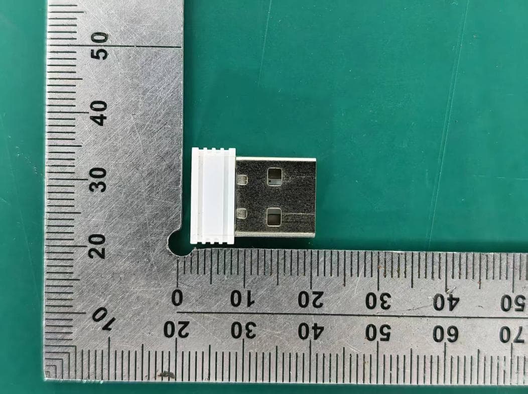
PRDRX12
May 27, 2026Wireless Receiver
Equipment Class
DXX - Part 15 Low Power Communication Device Transmitter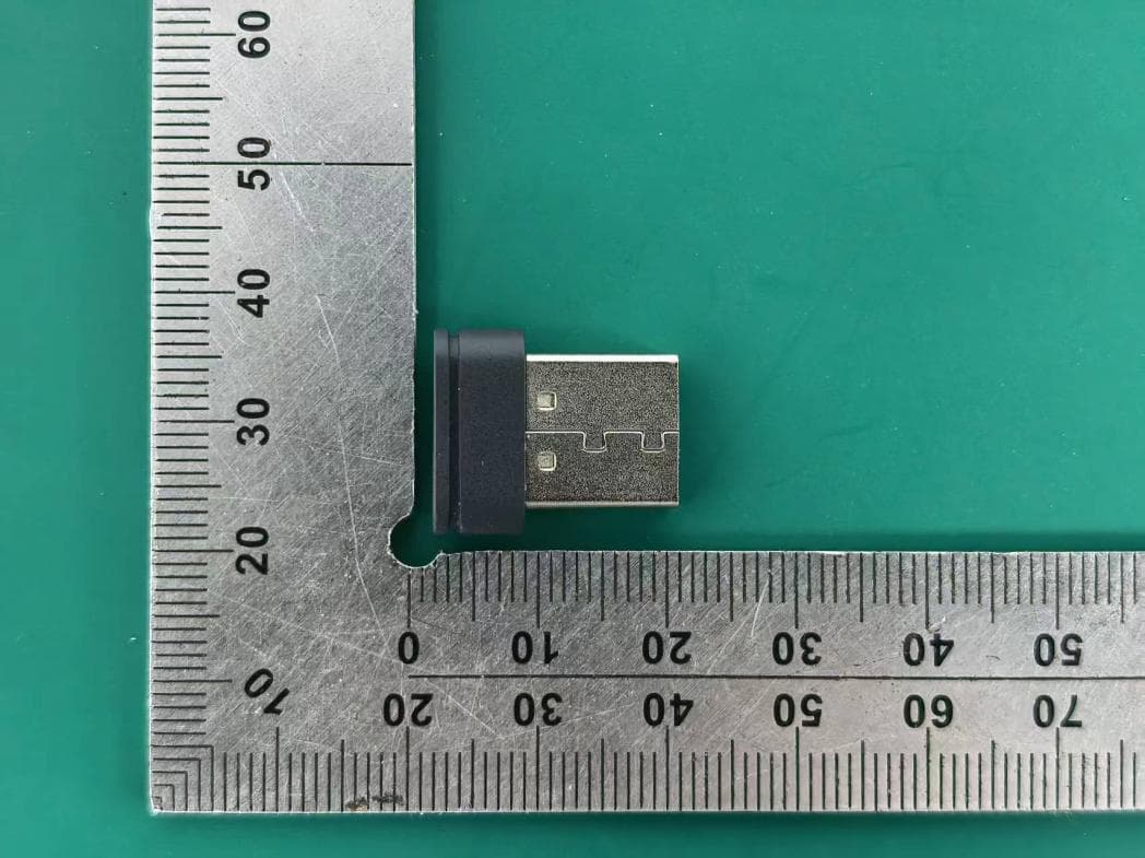
PRDRX11
Apr 07, 2026Wireless Receiver
Equipment Class
DXX - Part 15 Low Power Communication Device Transmitter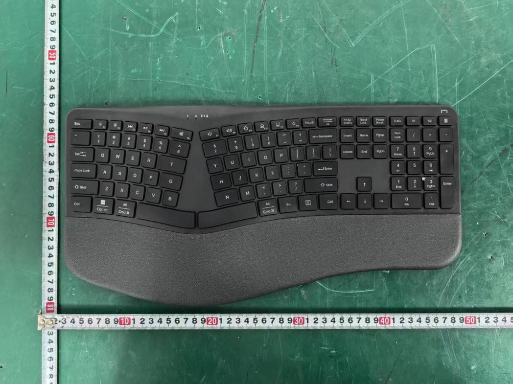
PRDKB72
Apr 03, 2026WIRELESS SPLIT KEY ERGONOMIC KEYBOARD
Equipment Class
DTS - Digital Transmission System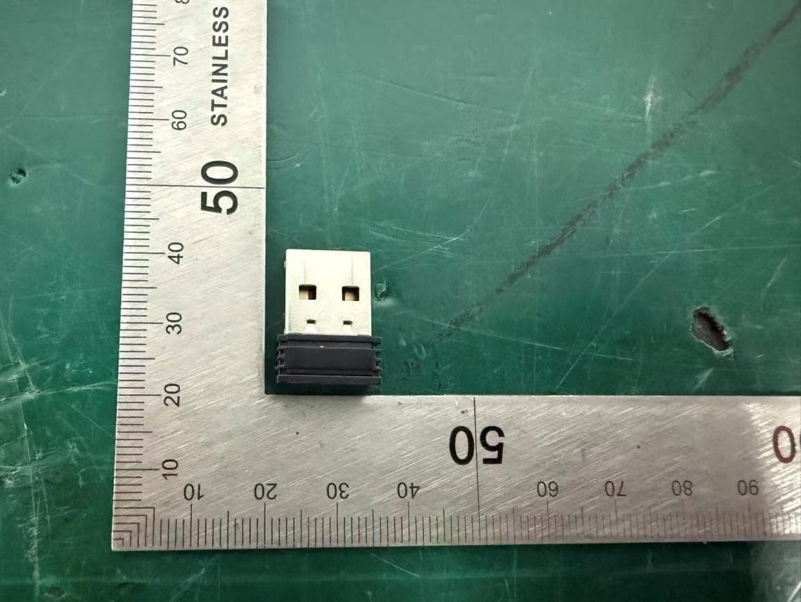
PRDRX1P
Apr 03, 2026Wireless Receiver
Equipment Class
DXX - Part 15 Low Power Communication Device Transmitter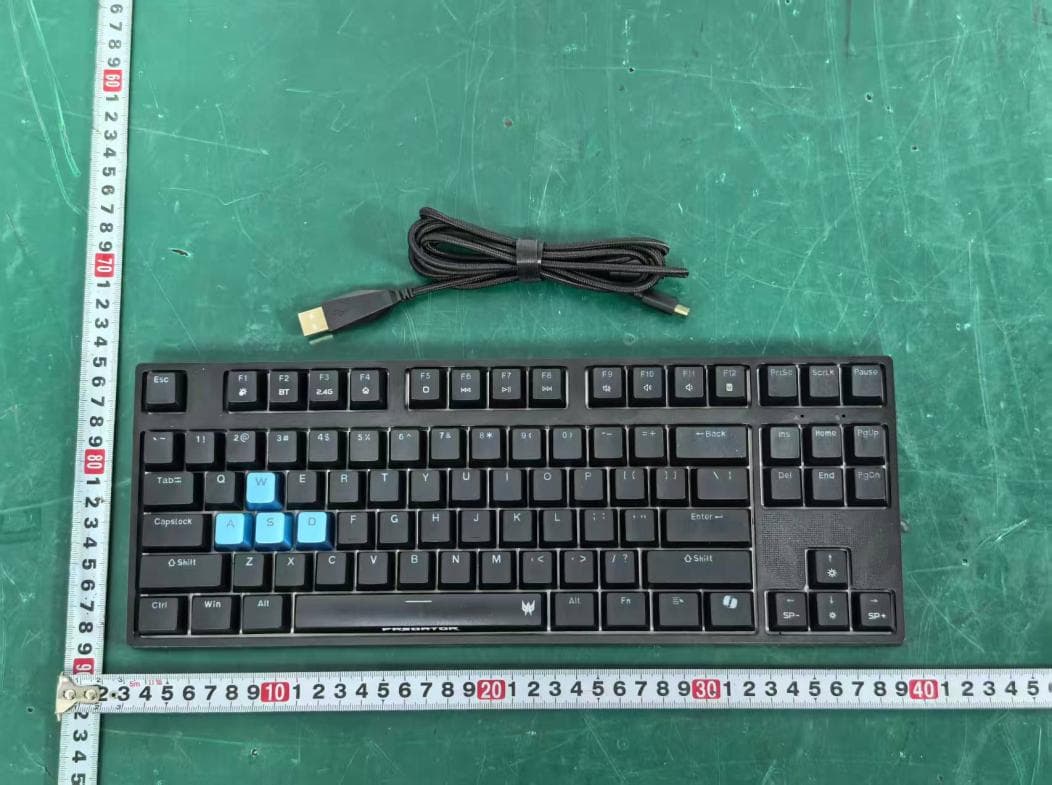
PRDKB73
Apr 03, 2026Gaming Keyboard
Equipment Class
DTS - Digital Transmission System