PRDOPWIRWMU27Wireless Mouse
Acrox Technologies Co., Ltd.
Click to zoom
Application Details
- Equipment Class
- DXX - Part 15 Low Power Communication Device Transmitter
- Date of Grant
- Mar 21, 2011
- Application Purpose
- Original Equipment
- Date of Application
- Mar 21, 2011
- Equipment Note
- Wireless Mouse
- Frequency Range
- 2403.00000000 - 2480.00000000
- Company
- Acrox Technologies Co., Ltd.
- Country
- Taiwan
Documents & Files
Document Text
Text extracted from the exhibit documents filed with the FCC. Open a document above to read the original.
Users Manual
2.4GHz Wireless BlueTrace™ Mouse w/Nano Receiver USER'S GUIDE Ver.:1.00 Class 1 LED Product CAUTION: To use this product properly, please read the user's guide before installing. 1 Federal Communication Commission Interference Statement This equipment has been tested and found to comply with the limits for a Class B digital device, pursuant to Part 15 of the FCC Rules. These limits are designed to provide reasonable protection against harmful interference in a residential installation. This equipment generates, uses and can radiate radio frequency energy and, if not installed and used in accordance with the instructions, may cause harmful interference to radio communications. However, there is no guarantee that interference will not occur in a particular installation. If this equipment does cause harmful interference to radio or television reception, which can be determined by turning the equipment off and on, the user is encouraged to try to correct the interference by one of the following measures: - Reorient or relocate the receiving antenna. - Increase the separation between the equipment and receiver. - Connect the equipment into an outlet on a circuit different from that to which the receiver is connected. - Consult the dealer or an experienced radio/TV technician for help. FCC Caution: Any changes or modifications not expressly approved by the party responsible for compliance could void the user's authority to operate this equipment. This device complies with Part 15 of the FCC Rules. Operation is subject to the following two conditions: (1) This device may not cause harmful interference, and (2) this device must accept any interference received, including interference that may cause undesired operation. 2 Functional Introduction Installing the batteries Step 1: Take the battery cover off. Step 2: Insert the batteries as shown inside the battery compartment. Step 3: Replace the cover. **Warning: *Please insert the battery with the correct position according to the instruction labeled on the mouse. Nano Receiver Scrolling Wheel & LED Indicator Left button Connect Button Right button Battery Cover Pull AAA Battery 1’st 2’nd ON/OFF Switch 3 Nano Receiver Setup the Connection between the Receiver and the Mouse 1. Insert the batteries into the mouse, then follow the steps below. 2. Plug the Nano receiver into the USB port of your computer. 3. If the mouse is not working, please put it into pairing mode. 4. Pairing: Re-plug the receiver into the USB port of your computer, then press the connect button on the mouse. If the mouse does not work after 10 seconds, pair them again. (The receiver has auto pairing function). Take out Push 4 5. The LED indicator on mouse flashes steadily when it is in pairing mode and stops blinking when it is successfully paired with the receiver. 6. When the batteries’ power of the mouse is low, the Low Power indicator will start to blink. LED Indicator *Mouse Indicator LED Blinks 3 times During Pairing LED is on 3 sec. Power ON Low Battery Warning will blink 10 times when turn on.
External Photos
Page 1 CONSTRUCTION PHOTOS OF EUT
ID Label/Location Info
Label Location
Internal Photos
Page 2 Page 3 Page 4
Operational Description
FCC ID: PRDOPWIRWMU27 Report No.: RF110125C21 Operational Description This device is a Wireless Mouse. The transmitter of the EUT is powered by 3Vdc from (1.5Vdc battery *2). The antenna is printed antenna. The other instruction, please have a look at the users manual.
Test Report
Report No.: RF110125C21 2 Report Format Version 4.0.0 Table of Contents RELEASE CONTROL RECORD.............................................................................................3 1. CERTIFICATION.......................................................................................................4 2. SUMMARY OF TEST RESULTS................................................................................5 2.1 MEASUREMENT UNCERTAINTY.............................................................................5 3. GENERAL INFORMATION........................................................................................6 3.1 GENERAL DESCRIPTION OF EUT..........................................................................6 3.2 DESCRIPTION OF TEST MODES............................................................................7 3.2.1 CONFIGURATION OF SYSTEM UNDER TEST........................................................7 3.2.2 TEST MODE APPLICABILITY AND TESTED CHANNEL DETAIL.............................8 3.3 GENERAL DESCRIPTION OF APPLIED STANDARDS............................................9 3.4 DESCRIPTION OF SUPPORT UNITS.......................................................................9 4. TEST TYPES AND RESULTS..................................................................................10 4.1 RADIATED EMISSION MEASUREMENT................................................................10 4.1.1 LIMITS OF RADIATED EMISSION MEASUREMENT..............................................10 4.1.2 TEST INSTRUMENTS.............................................................................................11 4.1.3 TEST PROCEDURES.............................................................................................12 4.1.4 DEVIATION FROM TEST STANDARD....................................................................12 4.1.5 TEST SETUP..........................................................................................................13 4.1.6 EUT OPERATING CONDITIONS.............................................................................13 4.1.7 TEST RESULTS......................................................................................................14 4.2 BAND EDGES MEASUREMENT.............................................................................20 4.2.1 LIMITS OF BAND EDGES MEASUREMENT..........................................................20 4.2.2 TEST INSTRUMENTS.............................................................................................20 4.2.3 TEST PROCEDURE................................................................................................20 4.2.4 DEVIATION FROM TEST STANDARD....................................................................20 4.2.5 EUT OPERATING CONDITION...............................................................................20 4.2.6 TEST RESULTS......................................................................................................21 5. PHOTOGRAPHS OF THE TEST CONFIGURATION...............................................23 6. INFORMATION ON THE TESTING LABORATORIES.............................................24 7. APPENDIX A – MODIFICATION RECORDERS FOR ENGINEERING CHANGES TO THE EUT BY THE LAB............................................................................................25 Report No.: RF110125C21 3 Report Format Version 4.0.0 RELEASE CONTROL RECORD ISSUE NO. REASON FOR CHANGE DATE ISSUED Original release N/A Feb. 10, 2011 Report No.: RF110125C21 5 Report Format Version 4.0.0 2. SUMMARY OF TEST RESULTS The EUT has been tested according to the following specifications: APPLIED STANDARD: FCC Part 15, Subpart C (Section 15.249) STANDARD PARAGRAPH TEST TYPE RESULT REMARK 15.207 Conducted Emission Test NA Power supply is 3Vdc from batteries. 15.209 15.249 15.249 (d) Radiated Emission Test Band Edge Measurement Limit: 50dB less than the peak value of fundamental frequency or meet radiated emission limit in section 15.209 PASS Meet the requirement of limit. Minimum passing margin is -8.1dB at 4960.00MHz. 2.1 MEASUREMENT UNCERTAINTY Where relevant, the following measurement uncertainty levels have been estimated for tests performed on the EUT as specified in CISPR 16-4-2: MEASUREMENT FREQUENCY UNCERTAINTY 30MHz ~ 200MHz 3.34 dB 200MHz ~1000MHz 3.35 dB 1GHz ~ 18GHz 2.26 dB Radiated emission 18GHz ~ 40GHz 1.94 dB This uncertainty represents an expanded uncertainty expressed at approximately the 95% confidence level using a coverage factor of k=2. Report No.: RF110125C21 7 Report Format Version 4.0.0 3.2 DESCRIPTION OF TEST MODES 78 channels are provided to this EUT. Channel Freq. (MHz) Channel Freq. (MHz) Channel Freq. (MHz) 1 2403 27 2429 53 2455 2 2404 28 2430 54 2456 3 2405 29 2431 55 2457 4 2406 30 2432 56 2458 5 2407 31 2433 57 2459 6 2408 32 2434 58 2460 7 2409 33 2435 59 2461 8 2410 34 2436 60 2462 9 2411 35 2437 61 2463 10 2412 36 2438 62 2464 11 2413 37 2439 63 2465 12 2414 38 2440 64 2466 13 2415 39 2441 65 2467 14 2416 40 2442 66 2468 15 2417 41 2443 67 2469 16 2418 42 2444 68 2470 17 2419 43 2445 69 2471 18 2420 44 2446 70 2472 19 2421 45 2447 71 2473 20 2422 46 2448 72 2474 21 2423 47 2449 73 2475 22 2424 48 2450 74 2476 23 2425 49 2451 75 2477 24 2426 50 2452 76 2478 25 2427 51 2453 77 2479 26 2428 52 2454 78 2480 3.2.1 CONFIGURATION OF SYSTEM UNDER TEST *Test table EUT (Power from batteries) Report No.: RF110125C21 8 Report Format Version 4.0.0 3.2.2 TEST MODE APPLICABILITY AND TESTED CHANNEL DETAIL APPLICABLE TO EUT CONFIGURE MODE RE≥1G RE<1G PLC BM DESCRIPTION - √ √ NOTE √ - Where RE<1G: Radiated Emission below 1GHz RE≥1G: Radiated Emission above 1GHz BM: Bandedge Measurement NOTE: No need to concern of Conducted Emission due to the EUT is powered by battery. RADIATED EMISSION TEST (ABOVE 1 GHz): Pre-Scan has been conducted to determine the worst-case mode from all possible combinations between available modulations axis and antenna ports (if E…
Text truncated - open the document above for the full version.
Test Setup Photos
1 PHOTOGRAPHS OF THE TEST CONFIGURATION RADIATED EMISSION TEST
Contact Information
Applicant
Gavin Hsieh(Product Manager)
Technical Contact
Bureau Veritas CPS (H.K.) Ltd. Taoyuan BranchGary Chang
[email protected]886-3-3183232
No. 19, Hwa Ya 2nd Rd., Kwei Shan Hsiang · Taoyuan Hsien · Taiwan
Non-Technical Contact
Bureau Veritas CPS (H.K.) Ltd. Taoyuan BranchWendy Liao
[email protected]886-3-3183232
Test Firm
Bureau Veritas CPS (H.K.) Ltd. Taoyuan BranchRichard Chen
Technical Specifications
| # | Rule Parts | Frequency Range | Power Output |
|---|---|---|---|
| 1 | 15C | 2.40 GHz - 2.48 GHz | - |
Other Applications from Acrox Technologies Co., Ltd.
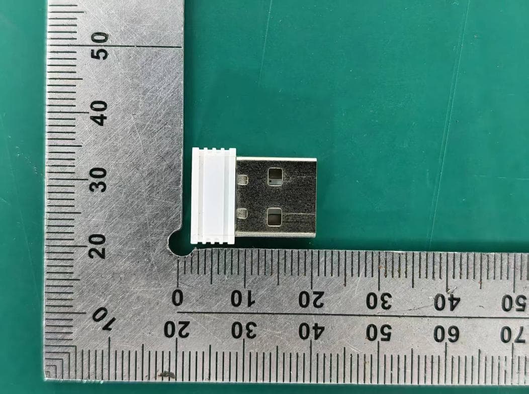
PRDRX12
May 27, 2026Wireless Receiver
Equipment Class
DXX - Part 15 Low Power Communication Device Transmitter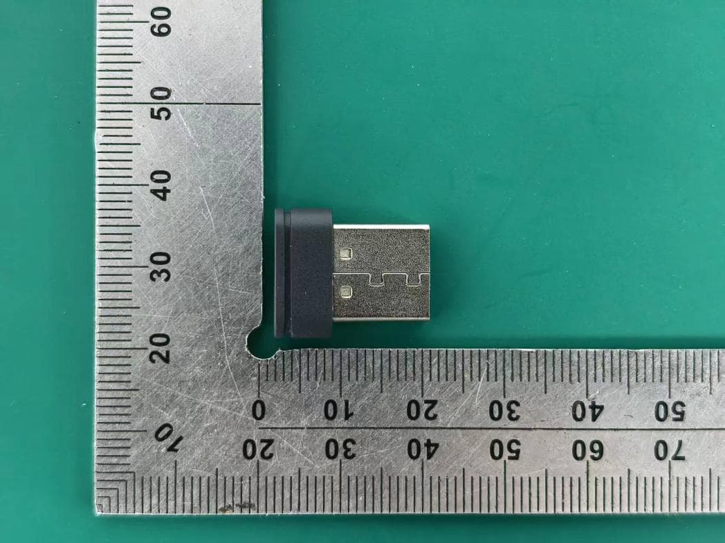
PRDRX11
Apr 07, 2026Wireless Receiver
Equipment Class
DXX - Part 15 Low Power Communication Device Transmitter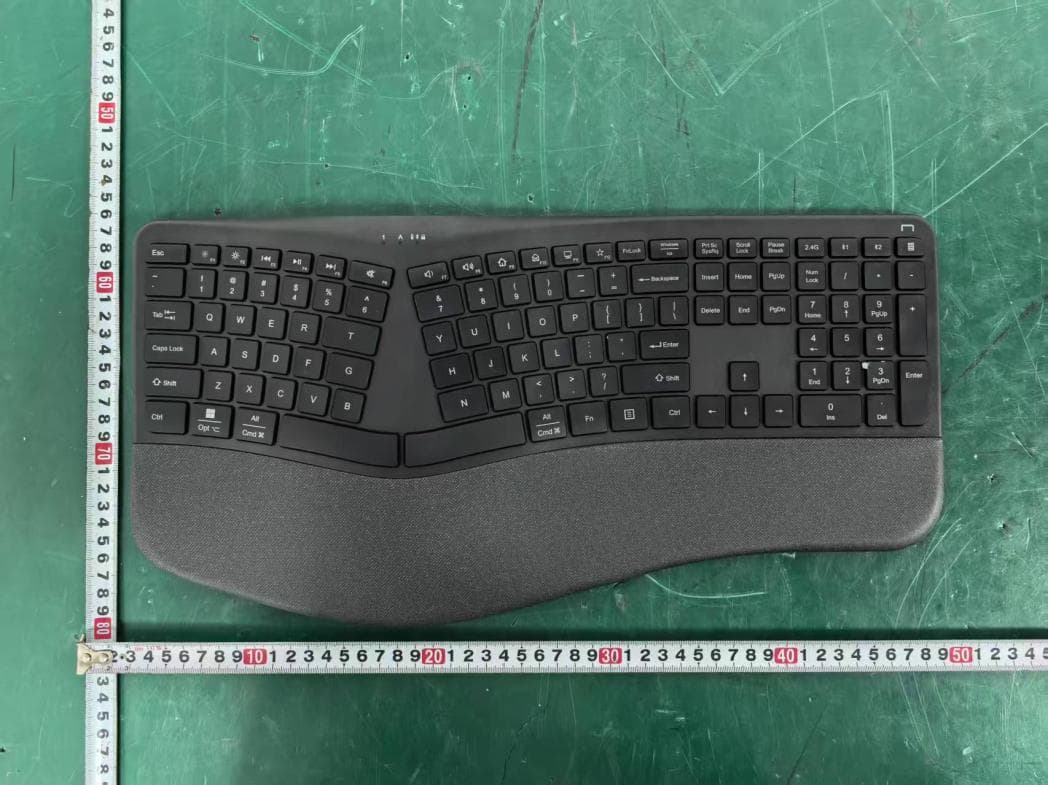
PRDKB72
Apr 03, 2026WIRELESS SPLIT KEY ERGONOMIC KEYBOARD
Equipment Class
DTS - Digital Transmission System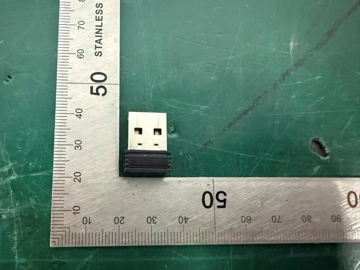
PRDRX1P
Apr 03, 2026Wireless Receiver
Equipment Class
DXX - Part 15 Low Power Communication Device Transmitter
PRDKB73
Apr 03, 2026Gaming Keyboard
Equipment Class
DTS - Digital Transmission System