PRDRX04Nano Receiver
Acrox Technologies Co., Ltd.Application Details
- Equipment Class
- DXT - Part 15 Low Power Transceiver, Rx Verified
- Date of Grant
- Jul 18, 2011
- Application Purpose
- Original Equipment
- Date of Application
- Jul 18, 2011
- Equipment Note
- Nano Receiver
- Frequency Range
- 2408.00000000 - 2474.00000000
- Company
- Acrox Technologies Co., Ltd.
- Country
- Taiwan
Documents & Files
Document Text
Text extracted from the exhibit documents filed with the FCC. Open a document above to read the original.
Users Manual
2.4GHz Wireless Optical Mouse w/Nano Receiver Model# : M250R USER'S GUIDE Ver.:1.00 CAUTION: To use this product properly, please read the user's guide before installing. 1 Federal Communication Commission Interference Statement This equipment has been tested and found to comply with the limits for a Class B digital device, pursuant to Part 15 of the FCC Rules. These limits are designed to provide reasonable protection against harmful interference in a residential installation. This equipment generates, uses and can radiate radio frequency energy and, if not installed and used in accordance with the instructions, may cause harmful interference to radio communications. However, there is no guarantee that interference will not occur in a particular installation. If this equipment does cause harmful interference to radio or television reception, which can be determined by turning the equipment off and on, the user is encouraged to try to correct the interference by one of the following measures: - Reorient or relocate the receiving antenna. - Increase the separation between the equipment and receiver. - Connect the equipment into an outlet on a circuit different from that to which the receiver is connected. - Consult the dealer or an experienced radio/TV technician for help. FCC Caution: Any changes or modifications not expressly approved by the party responsible for compliance could void the user's authority to operate this equipment. This device complies with Part 15 of the FCC Rules. Operation is subject to the following two conditions: (1) This device may not cause harmful interference, and (2) this device must accept any interference received, including interference that may cause undesired operation. 2 Functional Introduction Installing the batteries Step 1: Pull the battery cover backward. Step 2: Insert the batteries as shown inside the battery compartment. Step 3: Replace the cover. Step 4: Turn on power switch. **Warning: *Please insert the battery with the correct position according to the instruction labeled on the mouse. AAA Battery Left button Right button Battery Cover Scrolling Wheel Connect Button ON/OFF Switch Nano Receiver LED Indicator 3 Setup the Connection between the Receiver and the Mouse 1. Insert the battery into the mouse, then follow the steps below. 2. Plug the Nano receiver into the USB port on your computer. 3. If the mouse does not work, please put it into pairing mode. 4. Pairing: Re-plug the receiver into the USB port on your computer, then press the connect button on the mouse. If the mouse does not work after 10 seconds, pair them again. (The receiver has auto pairing function). 5. The LED indicator on mouse flashes steadily when it is in pairing mode and stops blinking when it is successfully paired with the receiver. 6. When low battery, the battery indicator on the mouse will start to blink. LED Indicator *Mouse Indicator LED Blinks for 10 sec. Low Battery Warning LED is on for 10 sec. Power ON LED Blinking Pairing (LED OFF when paired or failed after 10 sec.)
Cover Letter(s)
SCS-F18: Project and Product Certification Representative Authorization Letter Page 1 of 2 Rev 2.0 2206 Ringwood Avenue San Jose, CA 95131 Tel: 408-526-1188 Fax: 408-526-1088 Email: [email protected] Project and Product Certification Representative Authorization Letter Revision History Reason for Amendment (current / obsolete) From To Approved Date Initial Release (current) 1.0 1.0 Nov-14-2006 Revised wording (current) 1.0 2.0 Sept–25-2007 SCS-F18: Project and Product Certification Representative Authorization Letter Page 2 of 2 Rev 2.0 2011/7/14 To: SIEMIC, INC. 2206 Ringwood Avenue, San Jose, CA 95131 USA Dear Sir/Madam, Re: Project and Product Certification Representative Authorization Letter We, Acrox Technologies Co.,Ltd hereby authorize SIEMIC, INC. to act as a Certification Body for certifying for the following project(s): Product description: Nano Receiver model name:MRN FCC ID: PRDRX04 We affirm that between SIEMIC and Acrox Technologies Co.,Ltd, any difference in understanding, including test plan, measurement methods, applicable standards and relevant procedures and processes have been resolved prior to commencement of testing activities. Sincerely, Client’s signature: Client’s name / title:Manager Contact information / address: Acrox Technologies Co.,Ltd.437,8F,Rui Guang Road,Nei Hu District,Taipei,Taiwan
Cover Letter(s)
SCS-F19: Confidentiality Request Letter Page 1 of 2 Rev 2.0 2206 Ringwood Avenue San Jose, CA 95131 Tel: 408-526-1188 Fax: 408-526-1088 Email: [email protected] Confidentiality Request Letter Revision History Reason for Amendment (current / obsolete) From To Approved Date Initial Release (current) 1.0 1.0 Nov-14-2006 Adding CFR 2.459 1.0 2.0 August – 11 - 2008 SCS-F19: Confidentiality Request Letter Page 2 of 2 Rev 2.0 2011/7/14 To: Federal Communications Commission Authorization and Evaluation Division 7435 Oakland Mills Road Columbia, MD Confidentiality Request regarding application for certification of FCC ID: PRDRX04 We hereby request confidential treatment of information accompanying this application as outlined below: - Schematics - Block Diagram - Operational Description The above materials contain trade secrets and proprietary information not customarily released to the public. The public disclosure of these materials may be harmful to the applicant and provide unjustified benefits to its competitors. The applicant understands that pursuant to Section 0.457 & 0.459 of the Rules, disclosure of this application and all accompanying documentation will not be made before the date of the Grant for this application. Sincerely, Client’s signature: Client’s name / title: Manager Contact information / address: Acrox Technologies Co.,Ltd.437,8F,Rui Guang Road,Nei Hu District,Taipei,Taiwan
Cover Letter(s)
DECLARATION OF CONFORMITY This Verification of Compliance is hereby issued to the product designated below. Product Nano Receiver Model MRN Trade name N/A Applicant Acrox Teachnologies Co., Ltd 4F., No89, Minshan St., Neihu Dist., Taipei City 114, Taiwan, R.O.C Applicable Standard(s) FCC Part 15 Subpart B Class B (DoC) Report No. SZ110629B07-EF Laboratory Compliance Certification Services Inc. No. 81-1, Lane 210, Bade 2nd Rd., Lujhu Township, Taoyuan County 33841, Taiwan (R.O.C.) Tel: +886-3-3240332/ Fax: +886-3-3245235 This device has been tested and found to comply with the stated standard(s), which is(are) required by the Federal Communications Committee. The test results are indicated in the test report and are applicable only to the tested sample identified in the report. Ethan Huang/ Section Manager COMPLIANCE CERTIFICATION SERVICES INC. Date: July 8, 2011
External Photos
1. PHOTOGRAPH OF EUT Figure 1 General Appearance of the EUT Figure 2 General Appearance of the EUT Figure 3 General Appearance of the EUT Figure 4 General Appearance of the EUT
ID Label/Location Info
Label Location
Internal Photos
Figure 1 Component Side of the PCB Figure 2 Component Side of the PCB Antenna
Test Report
FCC ID: PRDRX04 EST Technology Co.,Ltd Report No. ESTE-R1107005 FCC PART 15C TEST REPORT FOR CERTIFICATION On Behalf of Acrox Technologies Co,.Ltd Nano Receiver Model Number: MRN FCC ID: PRDRX04 Prepared for : Acrox Technologies Co,.Ltd 437,8f,Rui Guang Road,Nei Hu District,Taipei,Taiwan Prepared By : EST Technology Co., Ltd. Santun(guantai Road), Houjie Town, DongGuan City,GuangDong, China. Tel: 86-769-83081888-808 Report Number : ESTE-R1107005 Date of Test : July.1~14, 2011 Date of Report : July.14, 2011 FCC ID: PRDRX04 EST Technology Co.,Ltd Report No. ESTE-R1107005 TABLE OF CONTENTS Description Page 1. SUMMARY OF STANDARDS AND RESULTS.......................................................... 1-1 1.1. Description of Standards and Results .................................................................................. 1-1 2. GENERAL INFORMATION ......................................................................................... 2-1 2.1. Description of Device (EUT) ............................................................................................... 2-1 2.2. Tested Supporting System Details ....................................................................................... 2-2 2.3. EUT Configuration and operation conditions for test.......................................................... 2-2 3. POWER LINE CONDUCTED EMISSION TEST ....................................................... 3-1 3.1. Test Equipment .................................................................................................................... 3-1 3.2. Block Diagram of Test Setup ............................................................................................... 3-1 3.3. Power Line Conducted Emission Test Limits...................................................................... 3-1 3.4. Operating Condition of EUT................................................................................................ 3-2 3.5. Test Procedure...................................................................................................................... 3-2 3.6. Conducted Disturbance at Mains Terminals Test Results.................................................... 3-2 4. RADIATED EMISSION TEST ...................................................................................... 4-3 4.1. Test Equipment .................................................................................................................... 4-3 4.2. Block Diagram of Test Setup ............................................................................................... 4-3 4.3. Radiated Emission Limit Standard: FCC 15.209 and 15.249 .............................................. 4-4 4.4. Operating Condition of EUT................................................................................................ 4-5 4.5. Test Procedure...................................................................................................................... 4-5 4.6. Radiated Emission Test Results ........................................................................................... 4-5 5. 20 DB BANDWIDTH TEST ........................................................................................... 5-1 5.1. Test Equipment .................................................................................................................... 5-1 5.2. Limit..................................................................................................................................... 5-1 5.3. Test Results .......................................................................................................................... 5-1 6. BAND EDGE COMPLIANCE TEST ............................................................................ 6-1 6.1. Test Equipment .................................................................................................................... 6-1 6.2. Limit..................................................................................................................................... 6-1 6.3. Test Produce ......................................................................................................................... 6-1 6.4. Test Results .......................................................................................................................... 6-2 7. PHOTOGRAPH OF TEST ............................................................................................. 7-1 7.1. Photos of Conducted Emission Test (0.15-30MHz) ........................................................... 7-1 7.2. Photos of Radiated EmissionTest(30-1000MHz)................................................7-2 8. PHOTOGRAPH OF EUT ............................................................................................... 8-1 FCC ID: PRDRX04 EST Technology Co.,Ltd Report No. ESTE-R1107005 TEST REPORT CERTIFICATION Applicant :Acrox Technologies Co,.Ltd Manufacturer :Acrox Technologies Co,.Ltd EUT Description : Nano Receiver FCC ID : PRDRX04 (A) MODEL NO. : MRN (B) SERIAL NO. : N/A (C) POWER SUPPLY : DC 5V From PC (D) TEST VOLTAGE : DC 5V From PC Tested for comply with: FCC Rules and Regulations Part 15 Subpart C:2008 Test procedure used: ANSI C63.10:2009 The device described above is tested by EST Technology Co., Ltd. to confirm comply with all the FCC Part 15 Subpart C requirements. The test results are contained in this test report and EST Technology Co., Ltd. is assumed full responsibility for the accuracy and completeness of these tests. Also, this report shows that the Equipment under test (EUT) is to be technically compliant with the FCC requirements. Prepared by: Tested by: Approved by: Coco / Assistant Tata Chen/ Engineer Iceman Hu / Manager This test report is based on a single evaluation of one sample of above mentioned products. It is not permitted to be duplicated in extracts without written approval of EST Technology Co., Ltd. FCC ID:PRDRX04 page EST Technology Co.…
Text truncated - open the document above for the full version.
Test Setup Photos
1. PHOTOGRAPH OF TEST 1.1. Photos of Conducted Emission Test (0.15-30MHz) 1.2. Photos of Radiated Emission Test (30-1000MHz) (Above 1000MHz)
Contact Information
Applicant
Gavin Hsieh(Product Manager)
Test Firm
EST Technology Co.,LtdIceman Hu
[email protected]86-769-83081888
Technical Specifications
| # | Rule Parts | Frequency Range | Power Output |
|---|---|---|---|
| 1 | 15C | 2.41 GHz - 2.47 GHz | - |
Other Applications from Acrox Technologies Co., Ltd.
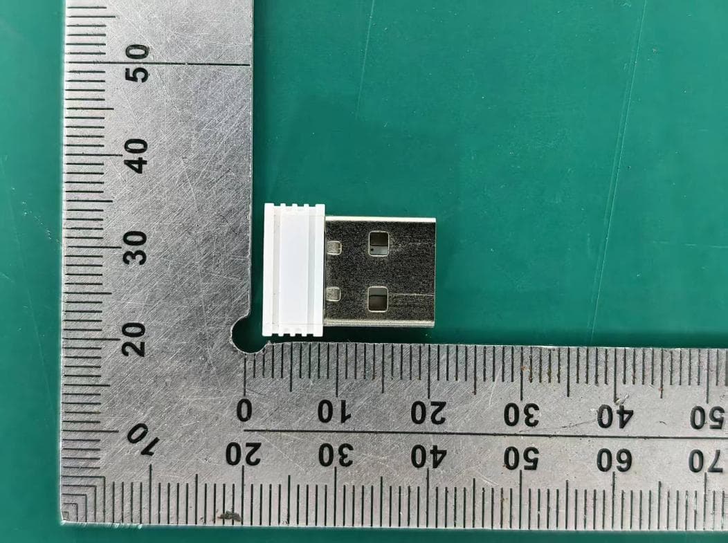
PRDRX12
May 27, 2026Wireless Receiver
Equipment Class
DXX - Part 15 Low Power Communication Device Transmitter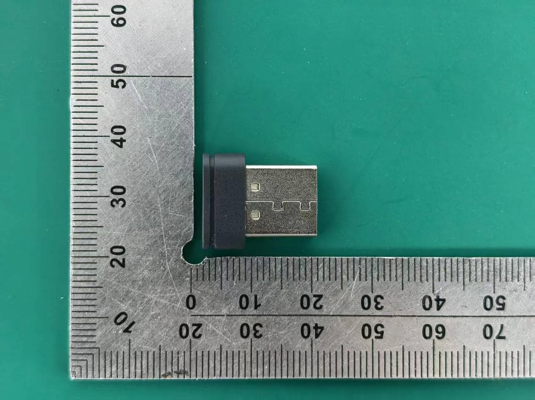
PRDRX11
Apr 07, 2026Wireless Receiver
Equipment Class
DXX - Part 15 Low Power Communication Device Transmitter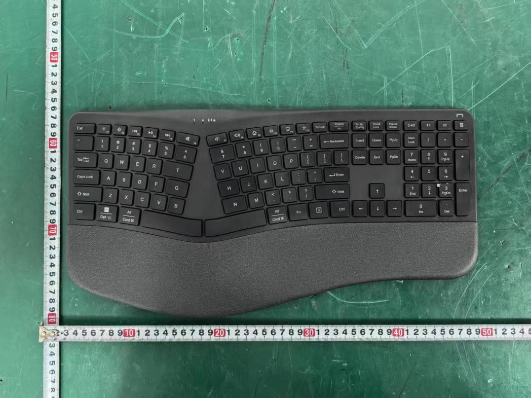
PRDKB72
Apr 03, 2026WIRELESS SPLIT KEY ERGONOMIC KEYBOARD
Equipment Class
DTS - Digital Transmission System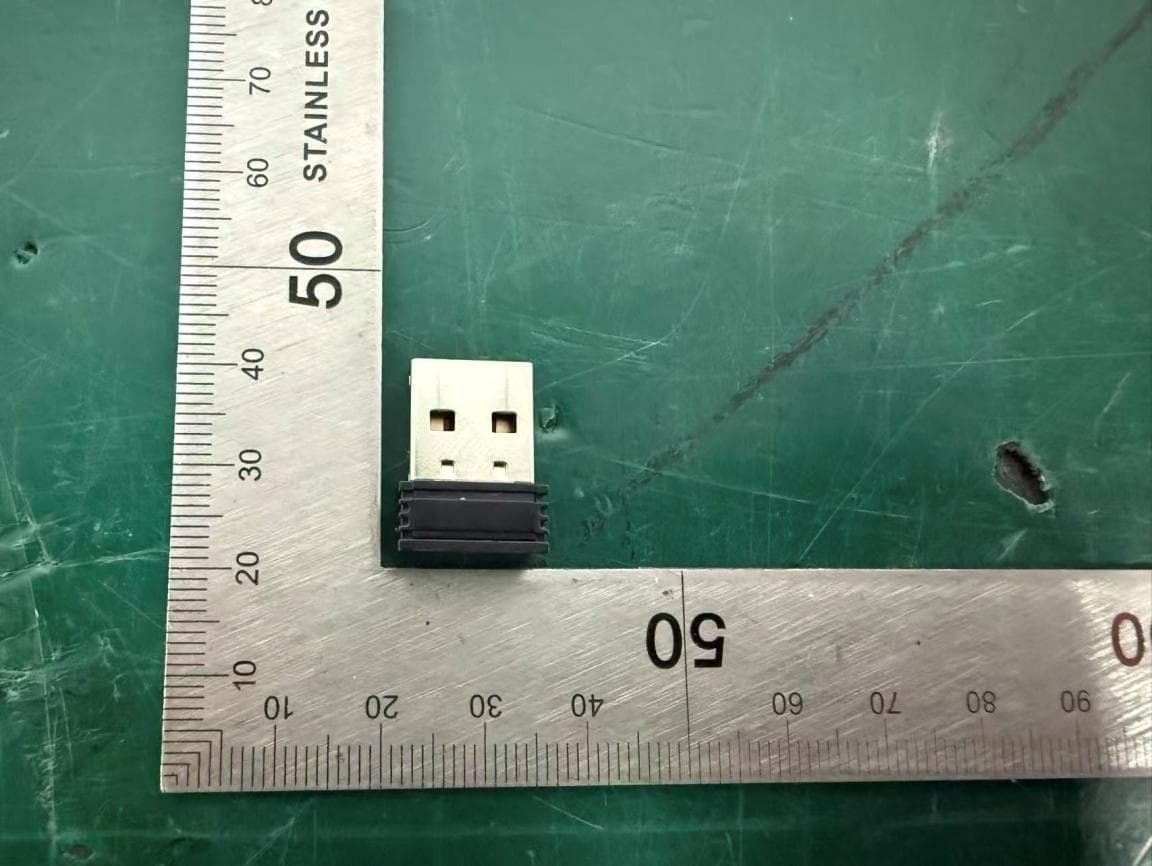
PRDRX1P
Apr 03, 2026Wireless Receiver
Equipment Class
DXX - Part 15 Low Power Communication Device Transmitter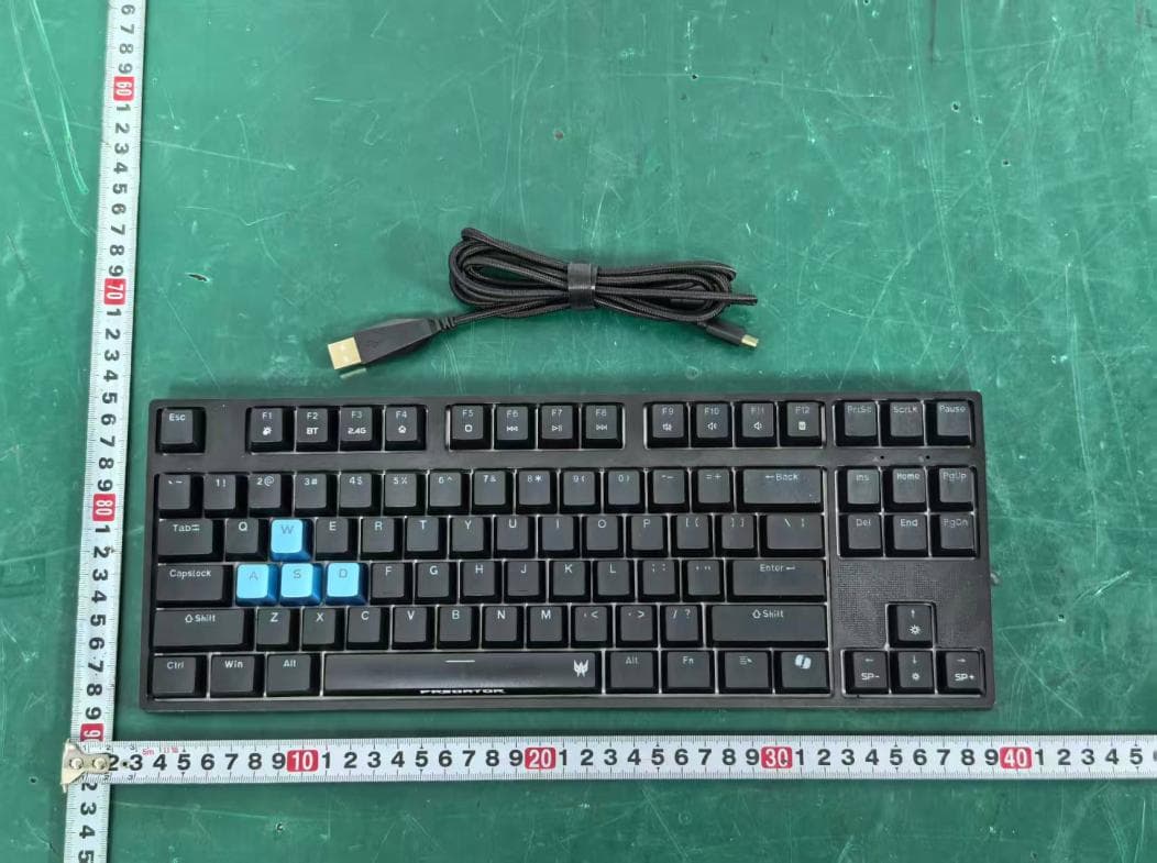
PRDKB73
Apr 03, 2026Gaming Keyboard
Equipment Class
DTS - Digital Transmission System