PRDRX1OWireless Receiver
Acrox Technologies Co., Ltd.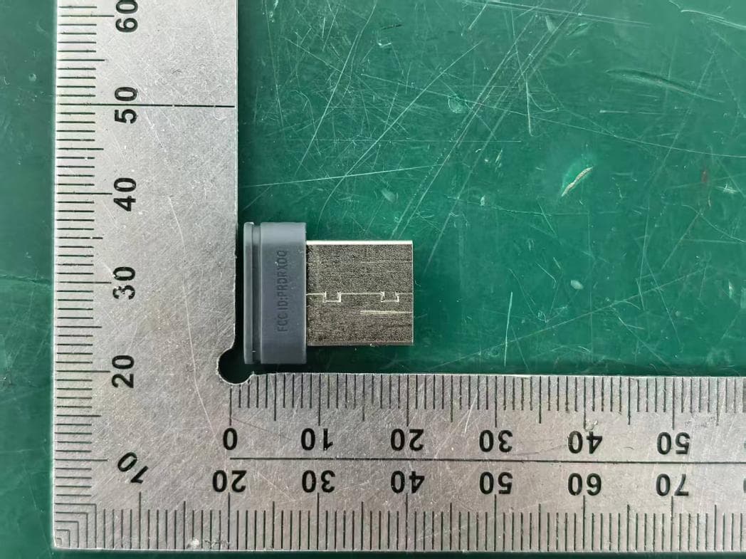
Click to zoom
Application Details
- Equipment Class
- DXX - Part 15 Low Power Communication Device Transmitter
- Date of Grant
- Mar 25, 2026
- Application Purpose
- Original Equipment
- Equipment Note
- Wireless Receiver
- Frequency Range
- 2402.00000000 - 2480.00000000
- Company
- Acrox Technologies Co., Ltd.
- Country
- Taiwan
Documents & Files
Document Text
Text extracted from the exhibit documents filed with the FCC. Open a document above to read the original.
Users Manual
Silent Wireless Keyboard & Mouse w/Nano Receiver USER'S GUIDE Ver.:1.00 CAUTION: To use this product properly, please read the user's guide before installation 1 Federal Communication Commission Interference Statement This equipment has been tested and found to comply with the limits for a Class B digital device, pursuant to Part 15 of the FCC Rules. These limits are designed to provide reasonable protection against harmful interference in a residential installation. This equipment generates, uses and can radiate radio frequency energy and, if not installed and used in accordance with the instructions, may cause harmful interference to radio communications. However, there is no guarantee that interference will not occur in a particular installation. If this equipment does cause harmful interference to radio or television reception, which can be determined by turning the equipment off and on, the user is encouraged to try to correct the interference by one of the following measures: - Reorient or relocate the receiving antenna. - Increase the separation between the equipment and receiver. - Connect the equipment into an outlet on a circuit different from that to which the receiver is connected. - Consult the dealer or an experienced radio/TV technician for help. FCC Caution: Any changes or modifications not expressly approved by the party responsible for compliance could void the user's authority to operate this equipment. This device complies with Part 15 of the FCC Rules. Operation is subject to the following two conditions: (1) This device may not cause harmful interference, and (2) this device must accept any interference received, including interference that may cause undesired operation. Radiation Exposure Statement: The product comply with the FCC portable RF exposure limit set forth for an uncontrolled environment and are safe for intended operation as described in this manual. The further RF exposure reduction can be achieved if the product can be kept as far as possible from the user body or set the device to lower output power if such function is available. 2 Functional Introduction Mouse Buttons 1. Left button 6 DPI Switch button & LED Indicator 2. Right button 7. Nano Receiver 3. Scrolling Wheel 8. Battery Cover 4. Forward 9. Connect Button 5. Backward 10 ON / OFF Switch Forward Press this button to view the next page in your Internet browser Backward Press this button to view the previous page in your Internet browser DPI Switch The LED indicator will light up when you plug the mouse into the USB port. The brightness of the indicator indicates the DPI setting in use. 3 a) 5 adjustable DPI settings. The number of blinks indicates the DPI setting in use DPI # of Blinks 800 dpi 1 1000 dpi 2 1600 dpi 3 2400 dpi 4 3600 dpi 5 b) The default setting is 1600 DPI. You can easily switch between DPI settings. Keyboard Buttons 4 Key Function (* compound key, Press with Fn key) 1. Media Player on Turn on the Media player program 2 Volume down (Voice-) Decrease the computer's sound volume. 3. Volume up (Voice+) Increase the computer's sound volume. 4. Mute Mute (turns off) the computer's sound 5. Previous Switch to the previous media track 6. Next Switch to the next media track 7. Play/Pause Switch between playing and pausing media 8. Stop(Media) Stop playing the media in the media player 9. Homepage(www/e) Start the default Web browser and loads the home Web page 10. Outlook(E-mail)Default Start the default e-mail program 11. My Computer My Computer 12. My Favorites Open My favorite after into Internet browser application 13. LED Indicator Num Lock / Caps Lock / Low Battery(Pairing Indicator) 14 ON/OFF Switch 15 Battery Cover Installing the batteries Step 1: Take the battery cover off. Step 2: Insert the battery as shown inside the battery compartment. 5 AAA Battery X 2 Pull AA Battery 6 Step 3: Replace the cover. Step 4: Turn on power switch. **Warning: *Please insert the battery with the correct position according to the instruction labeled on the mouse & Keyboard. Setup the Connection between the Receiver and the Mouse & Keyboard 1. Insert the battery into the mouse & Keyboard, then follow the steps below. 2. In the meantime, to open the cover under the mouse, take the nano receiver out. 7 3. Plug the Nano receiver into the USB port on your computer. 4. If the device does not work, please turn it into pairing mode. 5. Pairing: Re-plug the receiver into the USB port on your computer, then press connect button of the mouse and keyboard “ESC + K “. If the mouse or keyboard does not work after 10 seconds, pair them again. (The receiver has auto pairing function). 6. The LED indicator on the mouse & Keyboard flashes steadily when it is in pairing mode and stops blinking when it is successfully paired with the receiver. 7. When low battery, the battery indicator on the keyboard or the mouse will start to blink. 8 *Mouse Indicator LED is on for 10 sec. Power ON LED Blinking During Pairing (LED OFF when paired or failed after 10 sec.) LED Blinks for 10 sec. Low Battery Warning *Keyboard Indicator LED is on for 10 sec. Power ON LED Blinking During Pairing (LED OFF when paired or failed after 10 sec.) LED Blinks for 10 sec. Low Battery Warning LED Indicator LED indicator
Attestation Statements
Acrox Technologies Co., Ltd. Covered Equipment Certification Attestation Letter 3/23/2026 Federal Communications Commission Authorization and Evaluation Division 7435 Oakland Mills Road Columbia, MD 21046 USA ATTN.: Reviewing Engineer FCC ID: PRDRX1O Acrox Technologies Co., Ltd. (“the applicant”) certifies that the equipment for which authorization is sought is not “covered” equipment prohibited from receiving an equipment authorization pursuant to section 2.903 of the FCC rules. Note: If the equipment for which the applicant seeks authorization is produced by any of the entities identified on the current Covered List, the applicant should include an explanation on why the equipment is not “covered” equipment. Acrox Technologies Co., Ltd. (“the applicant”) certifies that, as of the date of the filing of the application, the applicant is not identified on the Covered List (as a specifically named entity or any of its subsidiaries or affiliates) as an entity producing “covered” equipment. Acrox Technologies Co., Ltd. (“the applicant”) certifies that the equipment for which authorization is sought does not include cybersecurity or anti-virus software produced or provided by Kaspersky Lab, Inc. or any of its successors and assignees, including equipment with integrated Kaspersky Lab, Inc. (or any of its successors and assignees) cybersecurity or anti-virus software pursuant to DA-24-886 and KDB 986446 D01 Covered Equipment Guidance section B(2a). Signed: Printed name: Gavin Hsieh Title: Product Manager Company Name: Acrox Technologies Co., Ltd. Date: 3/23/2026
Attestation Statements
Acrox Technologies Co., Ltd. * the applicant must designate a contact located in the United States for purposes of acting as the applicant’s agent for service of process, regardless of whether the applicant is a domestic or foreign entity. An applicant located in the United States may designate itself as the agent for service of process. U.S. Agent Designation for Service of Process - Certification Attestation Letter 3/23/2026 Federal Communications Commission Authorization and Evaluation Division 7435 Oakland Mills Road Columbia, MD 21046 USA ATTN.: Reviewing Engineer FCC ID: PRDRX1O FRN of applicant: 0018333633 Per section 2.911(d)(7) of the FCC rules, Acrox Technologies Co., Ltd. (“the applicant”) certifies that the equipment for which authorization is sought is designated to the following U.S. agent* for service of process: Company Name: 1PerfectChoice, Inc. FCC Registration Number (FRN): 0033429309 Physical U.S. Company Address: 21908 Valley Blvd., Walnut, CA 91789 Contact Person: Choon Kek Agent Email Address: [email protected] The above contact person accepts the obligation for service of process. The applicant accepts to maintain an agent for no less than one year after the grantee has terminated all marketing and importation or the conclusion of any Commission-related proceeding involving the equipment. Applicant Signed: Agent Signed (if different from Applicant): Signed: Signed: Printed name: Gavin Hsieh Printed name: Choon Kek Title: Product Manager Title: Chief Operating Officer Company Name: Acrox Technologies Co., Ltd. Company Name: 1PerfectChoice, Inc. Date: 3/23/2026 Date: 3/23/2026
Cover Letter(s)
DATE : 3/23/2026 Federal Communications Commission Authorization & Evaluation Division 7345 Oakland Mills Road Columbia, Maryland 21046 Authority to Act as Agent On our behalf, I appoint EST Technology Co., Ltd. Address:Chilingxiang, Qishantou, Santun, Houjie, Dongguan, Guangdong, China to act as our agent in the preparation of this application for equipment certification. I certify that submitted documents properly describe the device or system for which equipment certification is sought. I also certify that each unit manufactured, imported or marketed, as defined in the Federal Communications Commission’s regulations will have affixed to it a label identical to that submitted for approval with this application. For instances where our authorized agent signs the application for certification on our behalf, I acknowledge that all responsibility for complying with the terms and conditions for certification, still resides with Acrox Technologies Co., Ltd. Address:4F., No.89, Minshan St., Neihu Dist., Taipei City 114, Taiwan <Signature> Name:Gavin Hsieh Title:Product Manager Applicant Company:Acrox Technologies Co., Ltd.
Cover Letter(s)
DATE : 3/23/2026 Federal Communications Commission Authorization & Evaluation Division 7345 Oakland Mills Road Columbia, Maryland 21046 RE: LETTER OF AGENT AUTHORIZATION To Whom It May Concern: We, the undersigned, hereby authorize Compliance Testing, LLC to act on our behalf in all matters relating to application for equipment authorization, including the signing of all documents relating to these matters. We also hereby certify that no party to the application authorized hereunder is subject to the denial of benefits, including FCC benefits, pursuant to Section 5301 of the Anti-Drug Abuse Act of 1988, 21 U.S.C.853(a). Sincerely, <Signature> Name:Gavin Hsieh Title:Product Manager Company:Acrox Technologies Co., Ltd.
Cover Letter(s)
DATE : 3/23/2026 Equipment Autorisation Division Federal Communications Commission 7435 Oakland Mills Road Columbia, MD 21046 FCC ID: PRDRX1O Product Name: Wireless Receiver Request for Confidentiality Pursuant to Sections 0.457 and 0.459 of the commissions rules, we hereby request that the following documents be held confidential: Schematics Block diagram Operation description These materials contain trade secrets and proprietary information and are not customarily released to the public. The public disclosure of this information might be harmful to the company and provide unjustified benefits to our competitors. <Signature> Name:Gavin Hsieh Title:Product Manager Company:Acrox Technologies Co., Ltd.
External Photos
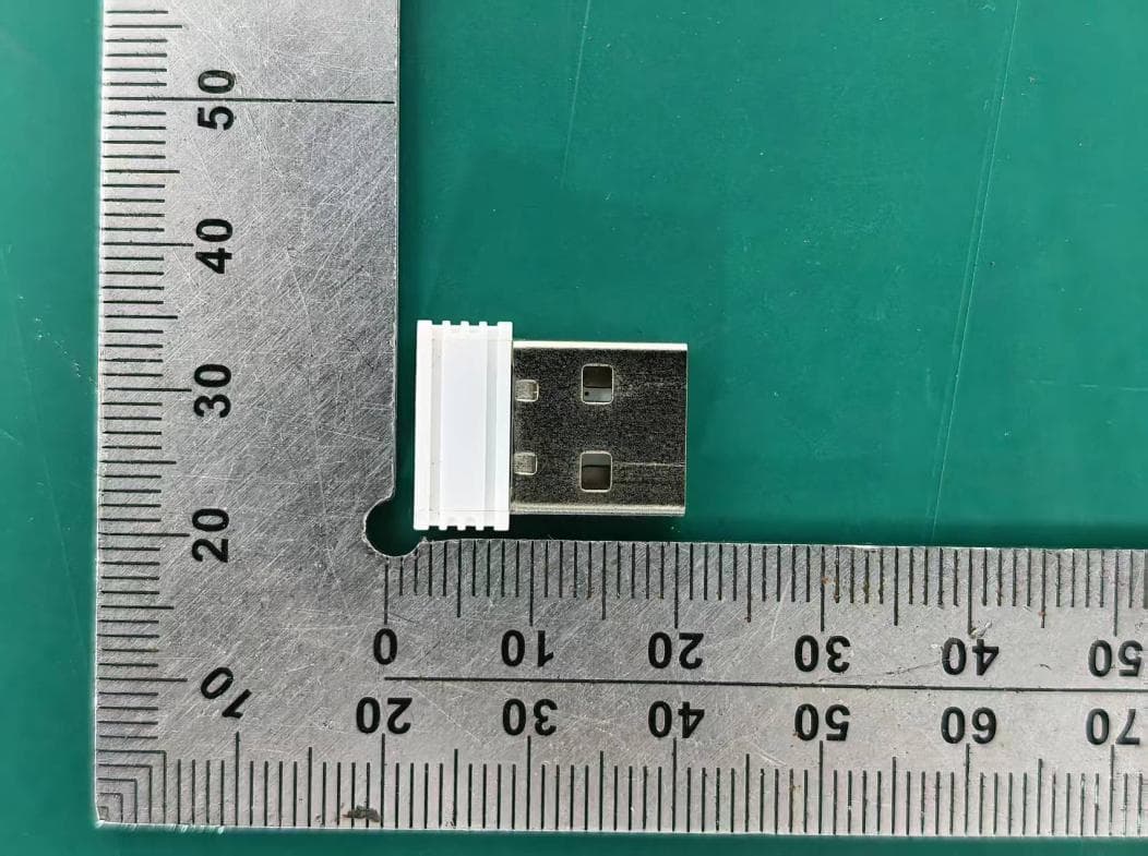
External Photos M/N: MX1 External Photos M/N: MX1 External Photos M/N: MX1
Internal Photos
Internal Photos M/N: MX1 Internal Photos M/N: MX1 2.4G SRD Antenna
RF Exposure Info
Page 1 of 3 Report No. ESTE-R2602074 FCC RF EXPOSURE REPORT Acrox Technologies Co., Ltd. Wireless Receiver Model Number: MX1 FCC ID: PRDRX1O Applicant: Acrox Technologies Co., Ltd. Address: 4F., No.89, Minshan St., Neihu Dist., Taipei City 114, Taiwan Prepared By: EST Technology Co., Ltd. Chilingxiang, Qishantou, Santun, Houjie, Dongguan, Guangdong, China Tel: 86-769-83081888-808 Report Number: ESTE-R2602074 Date of Test: Jan. 21, 2026 to Feb. 02, 2026 Date of Report: Feb. 06, 2026 Page 2 of 3 Report No. ESTE-R2602074 1. Applicable Standards FCC Part 2(Section 2.1093) FCC KDB 447498 D04 Interim General RF Exposure Guidance v01 2. Exposure Evaluation of Portable or Mobile Devices Human exposure to RF emissions from portable devices (47 CFR §2.1093), as defined by the FCC, must be evaluated with respect to the FCC-adopted limits for SAR. Evaluation of mobile devices, as defined by the FCC, may also be performed with respect to SAR limits, but in such cases it is usually simpler and more cost-effective to evaluate compliance with respect to field strength or power density limits. For certain devices that are designed to be used in both mobile and portable configurations similar to those described in 47 CFR §2.1091(d)(4), such as certain desktop phones and wireless modem modules, compliance for mobile configurations is also satisfied when the same device is evaluated for SAR compliance in portable configurations. The test exclusions are applicable only when the minimum test separation distance is ≤ 50 mm and for transmission frequencies between 300 MHz and 6 GHz. When the minimum test separation distance is < 5 mm, a distance of 5 mm is applied to determine SAR test exclusion. Page 3 of 3 Report No. ESTE-R2602074 3. Evaluation Results For 2.4G SRD Field strength =65.11dBuV/m@3m P={ [10 (65.11/20) /10 6 *3] 2 /30 }*1000mW =0.001mW< 2.72mW 1. Limited= 3060*(0.5/20)^(- (where f is in GHz); 2. We choose 2.480GHz to calculate limit as lower frequency will have higher limits. End of Test Report
Test Report
Page 1 of 51 Report No.ESTE-R2602073 FCC PART 15C TEST REPORT FOR CERTIFICATION On Behalf of Acrox Technologies Co., Ltd. Wireless Receiver Model Number: MX1 FCC ID: PRDRX1O Applicant: Acrox Technologies Co., Ltd. Address: 4F., No.89, Minshan St., Neihu Dist., Taipei City 114, Taiwan Prepared By: EST Technology Co., Ltd. Chilingxiang, Qishantou, Santun, Houjie, Dongguan, Guangdong, China Tel: 86-769-83081888-808 Report Number: ESTE-R2602073 Date of Test: Jan. 21, 2026 to Feb. 02, 2026 Date of Report: Mar. 23, 2026 Page 2 of 51 Report No.ESTE-R2602073 TABLE OF CONTENTS Description Page TEST REPORT VERIFICATION .......................................................................................................... 3 1. GENERAL INFORMATION ................................................................................................................ 5 1.1. Description of Device (EUT) ......................................................................................................... 5 1.2. Antenna Information ...................................................................................................................... 5 1.3. Information of RF Cable ................................................................................................................ 5 2. SUMMARY OF TEST ........................................................................................................................ 6 2.1. Summary of test result .................................................................................................................. 6 2.2. Test Facilities .................................................................................................................................. 7 2.3. Measurement uncertainty ............................................................................................................. 8 2.4. Assistant equipment used for test ............................................................................................... 8 2.5. Block Diagram ................................................................................................................................ 8 2.6. Test Mode ....................................................................................................................................... 9 2.7. Power Setting of Test Software ................................................................................................... 9 2.8. Channel List .................................................................................................................................... 9 2.9. Test Equipment List ..................................................................................................................... 10 3. FIELD STRENGTH OF FUNDAMENTAL .......................................................................................... 12 3.1. Limit ................................................................................................................................................ 12 3.2. Test Setup ..................................................................................................................................... 12 3.3. Spectrum Analyzer Setting ......................................................................................................... 12 3.4. Test Procedure ............................................................................................................................. 13 3.5. Test Result .................................................................................................................................... 14 4. RADIATED SPURIOUS EMISSIONS AND BAND EDGE ................................................................... 21 4.1. Limit ................................................................................................................................................ 21 4.2. Test Setup ..................................................................................................................................... 23 4.3. Spectrum Analyzer Setting ......................................................................................................... 24 4.4. Test Procedure ............................................................................................................................. 25 4.5. Test Result .................................................................................................................................... 26 5. 20DB BANDWIDTH ....................................................................................................................... 38 5.1. Limit ................................................................................................................................................ 38 5.2. Test Setup ..................................................................................................................................... 38 5.3. Spectrum Analyzer Setting ......................................................................................................... 38 5.4. Test Procedure ............................................................................................................................. 38 5.5. Test Condition .............................................................................................................................. 38 5.6. Test Result .................................................................................................................................... 39 6. ANTENNA REQUIREMENTS .......................................................................................................... 41 6.1. Limit ................................................................................................................................................ 41 6.2. Test Result .................................................................................................................................... 41 7. A…
Text truncated - open the document above for the full version.
Test Report
Dongle Antenna Specification Dongle PIFA Antenna The Nano Dongle antenna adopts the ultra-small PIFA antenna, and because of the limited area of PCB, the gain of the antenna will be smaller than that of other antennas. The communication distance can reach about 15 ~ 20 meters. The size of Dongle PCB antenna is 11.4 * 3mm and the thickness of PCB is 0.6mm.The specific size of the antenna is shown in figure 1, the physical object is shown in figure 2. Figure 1 :Nano Dongle Figure 2: Nano Dongle Antenna The antenna's S11 test data is shown in figure 3, covering the entire 2.4 G frequency band. Figure 3 :Nano Dongle Antenna S11 The gain simulation data of the antenna is shown in figure 4, with the maximum gain of -0.5dBi. Fig.4 Nano Dongle antenna gain and 3D direction diagram (the X-axis is the left and right direction of figure 1, and the Y-axis is the upper and lower direction of figure 1)
Test Setup Photos
Conducted Emissions Test Radiated Test (30-1000 MHz) Radiated Test (Above 1GHz)
Contact Information
Applicant
Gavin Hsieh(Product Manager)
[email protected]Fax: 886-2-2793-8999
Technical Contact
1PerfectChoice, Inc.Choon Kek
21908 Valley Blvd. · Walnut, California, 91789 · United States
Test Firm
EST Technology Co., Ltd.Iceman Hu
Technical Specifications
| # | Rule Parts | Frequency Range | Power Output |
|---|---|---|---|
| 1 | 15C | 2.40 GHz - 2.48 GHz | - |
Other Applications from Acrox Technologies Co., Ltd.
PRDRX12
May 27, 2026Wireless Receiver
Equipment Class
DXX - Part 15 Low Power Communication Device Transmitter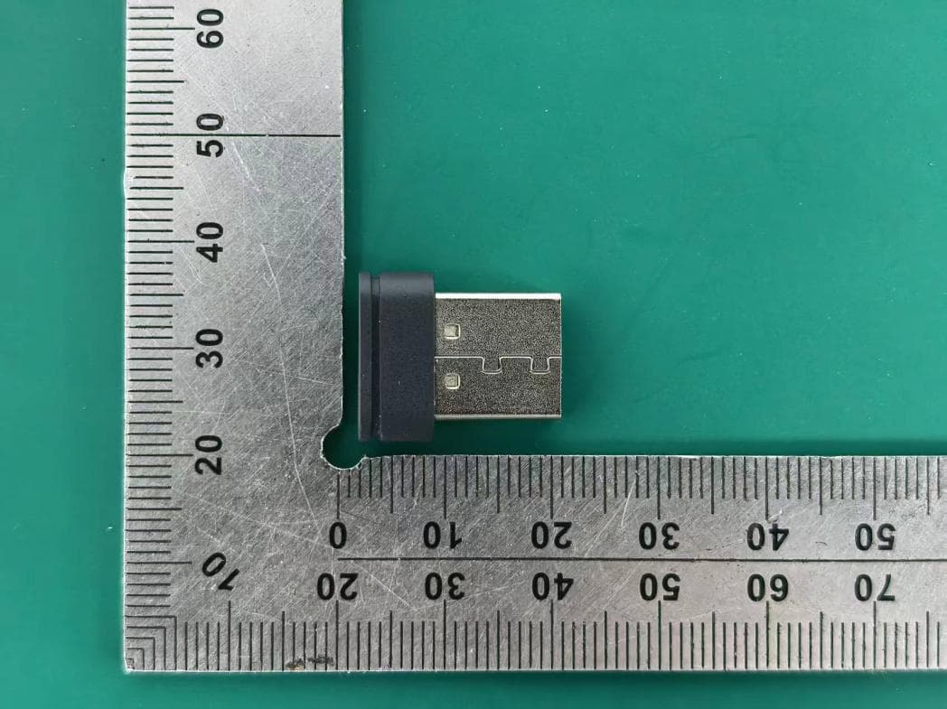
PRDRX11
Apr 07, 2026Wireless Receiver
Equipment Class
DXX - Part 15 Low Power Communication Device Transmitter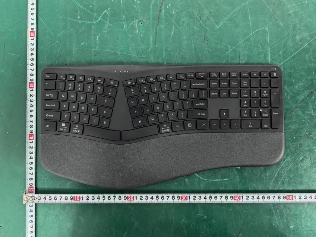
PRDKB72
Apr 03, 2026WIRELESS SPLIT KEY ERGONOMIC KEYBOARD
Equipment Class
DTS - Digital Transmission System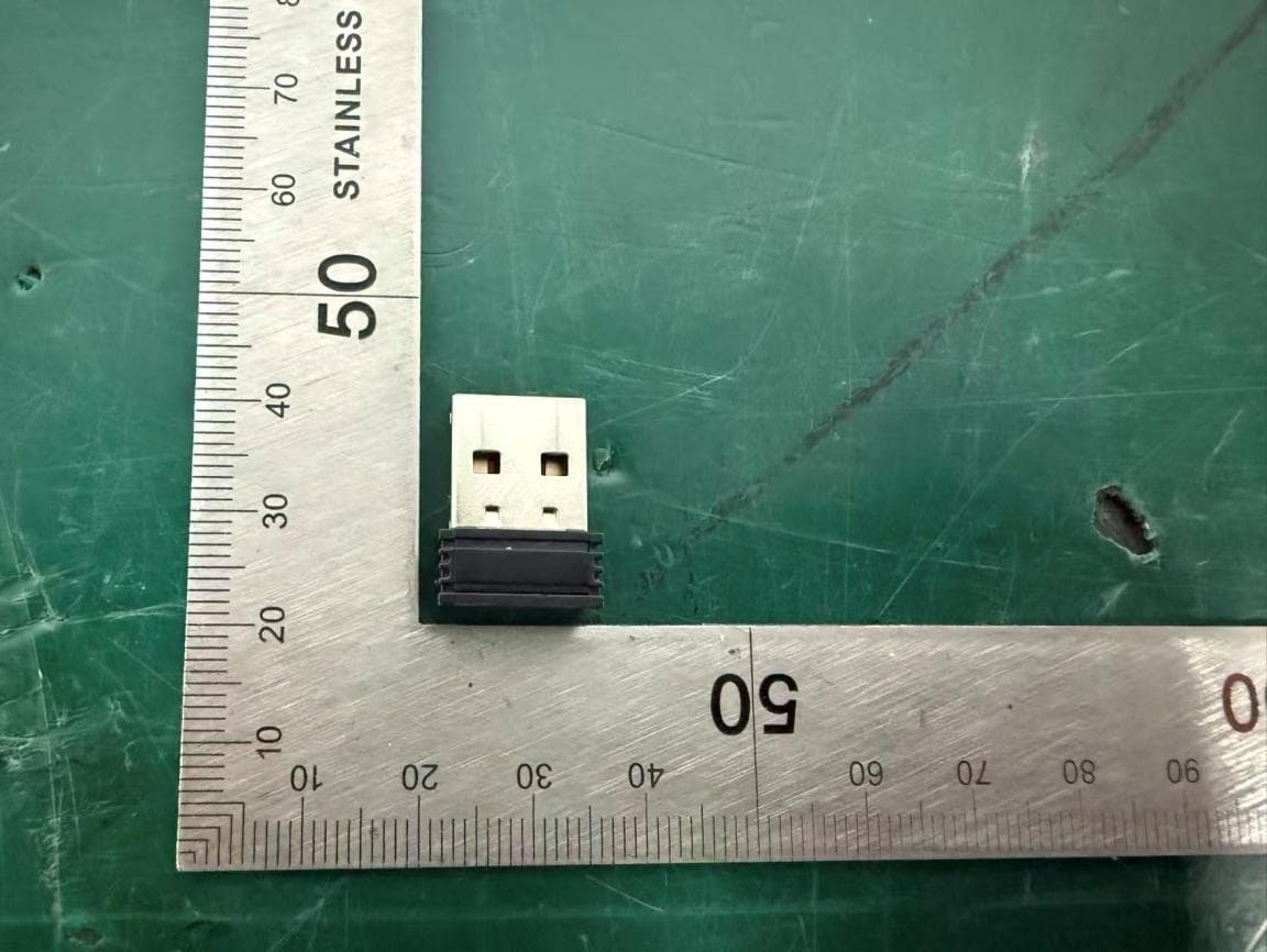
PRDRX1P
Apr 03, 2026Wireless Receiver
Equipment Class
DXX - Part 15 Low Power Communication Device Transmitter
PRDKB73
Apr 03, 2026Gaming Keyboard
Equipment Class
DTS - Digital Transmission System