PRK531102Bluetooth transmitter for palm type computers
Tactel AB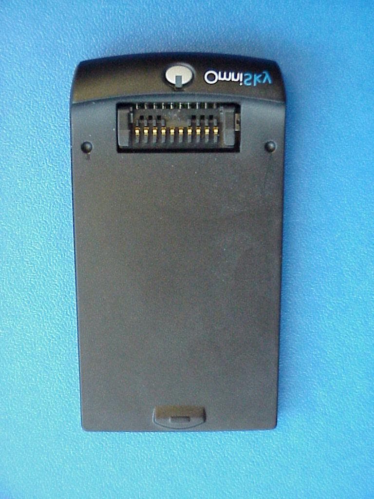
Click to zoom
Application Details
- Equipment Class
- DSS - Part 15 Spread Spectrum Transmitter
- Date of Grant
- Aug 21, 2001
- Application Purpose
- Original Equipment
- Date of Application
- Jul 04, 2001
- Equipment Note
- Bluetooth transmitter for palm type computers
- Frequency Range
- 2402.00000000 - 2480.00000000
- Company
- Tactel AB
- Country
- Sweden
Documents & Files
Document Text
Text extracted from the exhibit documents filed with the FCC. Open a document above to read the original.
Users Manual
2 Copyright and trademark notice The words HotSync, Palm and Palm OS are all registered trademarks of Palm Inc, or its subsidiaries in one or more countries. Other products and brand names may be the trademarks or registered trademarks of their respective owners. The BLUETOOTH trademark is owned by Telefonaktiebolaget L M Ericsson, Sweden. 3 Contents 1.0 Getting started...............................................................................................4 1.1 Package includes................................................................................................................................Ё 1.2 Setting up the hardware......................................................................................................................4 2.0 Installing the software...................................................................................4 2.1 Check the installation..........................................................................................................................4 3.1 Pairing basics................................................................................................................................ခ ᓱ鼀 늅倀 3.2.1 Connecting to your phone................................................................................................................4 3.2.2 Connecting to a computer.................................................................................................................5 3.3 Settings................................................................................................................................ḁ ᓱ鼀 늅倀يم 鼀 4.0 Palm Preferences...........................................................................................6 4.1 Network................................................................................................................................␁ ᓱ鼀 늅倀يم 鼀 擱鼀 5.0 Palm features.................................................................................................6 5.1 HotSync over Bluetooth......................................................................................................................6 5.2 Replicated port................................................................................................................................ఁ ᓱ鼀 6.0 Troubleshooting.............................................................................................7 6.1 The Button................................................................................................................................ᰁ ᓱ鼀 늅倀يم 鼀 6.2 Pairing problems................................................................................................................................ ᓱ 6.3 HotSync problems................................................................................................................................ȁ 6.4 Discoverable mode...............................................................................................................................7 7.0 Limitations......................................................................................................8 8.0 Blue5 regulatory information........................................................................8 8.1 FCC approval................................................................................................................................ሁ ᓱ鼀 늅倀 8.2 Canadian RFI Statement......................................................................................................................8 8.3 Euproean Union (EU) and EFTA..........................................................................................................8 4 1.0 Getting started 1.1 Package includes You should have in your possession a Blue5 and a CD containing all the software you will need to take full advantage of this Bluetooth device. This manual should be sufficient help to get you up and running with your new Blue5. 1.2 Setting up the hardware The Blue5 is to be connected to the bottom of the Palm. You will hear a clicking sound when it snaps on successfully. It uses power from the Palm, so you do not need an external cable of any kind. 2.0 Installing the software Make sure you have the Palm desktop installed and working on your computer. Then place your Palm in the cradle. The software needed for the Blue5 is located on the CD labelled Installation Disk. Put it in your CD-player and the Installation program will start automatically (if not, press the Start-menu and choose Run. Type the letter of your drive e. g d: and click on Startup). Follow the installation instructions, and the installation should proceed without any problems. 2.1 Check the installation After the installation you will find a new menu choice, on your Palm, in Prefs called Bluetooth preference screen. To find it, click the Application button followed by the Prefs icon. This application (as described in 3.0) is the main one you need for using the Bluetooth link. Tap on it and proceed to the next step in this manual. 3.0 Bluetooth preference screen The Bluetooth preference screen is the link to hook up your Palm with other Bluetooth devices. It is a user-friendly way to find, add and keep track of your Bluetooth devices. The process of linking up other Bluetooth devices is called Pair- ing, and will be referred to as that from now. Continue to 3.1 Pairing basics for the pairing basics. 3.1 Pairing basics From here your can connect your Palm to a Bluetooth device of your choice: To do this you must have your Bluetooth plug connected on your Palm. For the moment, the Blue5 supports pairing with mobile phones, computers (requires Bluetooth enabled computer) and other Palms (require Blue5 on both Palm’s). 5 3.2.1 Connecting to your phone Start by clicking on Add device in the Bluetooth Preference Screen. Now make sure that your phone is in *Discoverable mode before you select Phone from the type list and click Search on the Palm. Now the Palm will sea…
Text truncated - open the document above for the full version.
Block Diagram
RX- Balun Radio ASIC ANT T2 TX- Balun Switch Antenna Filter Loop Filter VCO Tank FLASH Memory 13MHz Crystal Voltage Regulation WAKE_UP DETACH GND B3 R1 R2 T1 C6 VCC C4 VCC_IO C2 ON RESET# POR NC NC NC NC NC R4 R5 R6 T4 T5 T6 C3 Radio Module B4 C1 ADDR DATA CTRL R3 C5 NC PBA 313 01/2 Baseband B1 D- D+ B2 USB TXD RTS RXD CTS A5 A6 B5 B6 UART PCM_OUT PCM_CLK PCM_IN PCM_SYNC A1 A2 A3 A4 PCM T3 GND GND GND GND I2C_DATA I2C_CLK Block diagram for Ericsson Bluetooth modules Rok 101 002/1 Radio set used in Rok 101 007
Cover Letter(s)
July 5, 2001 TRP/Cetecom bvba 14085 Howard Rd Dayton, MD 21036 Gentlemen: On behalf of Tactel AB herewith is an application for multiple list of an essentially identical equipment. Ericsson Microelectronics AB is the manufacturer of an approved Bluetooth module, FCC ID: PNI8001001. Because the physical size of the approved module is to large to fit their product, Tactel AB purchases the radio chip and the base band chip from Ericsson Microelectronics AB for implementation in their Bluetooth adapter for Palm Pilot type hand held computers. As such, their unit is both a transmitter subject to certification and a Class B peripheral subject to DOC. The implementation of the radio chip and base band chip on the Tactel PCB does not affect the performance of the radio. The processing gain is a function inherent in the chip design and reports showing the radio has the required processing gain have been previously submitted and accepted by the FCC. A copy of the original report as accepted by the FCC is being filed for reference purposes. Hopping system parameters are not affected as well as timing characteristics because these are functions of the chip design. Only rf related emissions are affected by the new layout and a measurement report is being submitted that shows the Tactel AB implementation complies with the FCC Rules. The antenna can be seen on the pcb photograph just below the Ericsson Radio chip. It is a pcb board strip line type. The modifications shown in the photograph will be implemented in all units that are manufactured. This device obtains power from the Palm computer to which it is attached. Regards, Phillip Inglis TRP/Cetecom bvba 14985 Howard Rd Dayton, MD 21036
Cover Letter(s)
July 5, 2001 CONFIDENTIALITY REQUEST Federal Communications Commission Authorization and Evaluation Division 7435 Oakland Mills Road Columbia, MD 21046 Re: Tactel AB application for Hybrid Spread Spectrum System, FCC ID:PRK531102 Gentlemen: Tactel AB Norra Vallgatan 64, Malmo Lomma, Sweden SE-21122, herein submits an Application for Equipment Authorization to be followed by submission of a fee for $1180.00 along with Form 159 for certification of a spread spectrum transmitter under FCC Rules Part 15 as required by the FCC Rules. Tactel AB requests, pursuant to 47CFR 0.459, post grant confidentiality for portions of the material contained in this application such that the identified material will be withheld from public inspection following the grant of this authorization. This material, as indicated by request for confidentiality of the item during the electronic submission process and further identified below, includes: 1. Circuit diagrams submitted as Equipment Authorization Electronic Filing attachment: "schematics". Specifically, this exhibit contains information relating to circuit function and complexity that could be of benefit to competitors. The material contains trade secrets and confidential information that Ericsson does not customarily release to the public and which is otherwise not generally available to the public. Please contact the undersigned by phone at 410-531-3439, by fax at 410-531-0807, by email at [email protected], or by correspondence at the address below if there are any further questions or additional information needed concerning this filing. Regards, (signed) Phillip Inglis, Cetecom b.v.b.a., Maryland 14085 Howard Rd. Dayton, MD. 21036
Cover Letter(s)
July 26, 2001 TRP/Cetecom bvba 14085 Howard Rd Dayton, MD 21036 Gentlemen: After speaking with a member of the FCC Laboratory staff, Mr. Dichoso, I would like to clarify what is meant by radio chip in the original cover letter. The references to radio chip in the correspondence refers to the complete radio transceiver assembly which is implemented in a single package. Thus, the processing gain measurements performed for FCC ID: CGK8001001 as referenced in FCC ID: PNI8001001, are applicable to this unit. Regards, Phillip Inglis TRP/Cetecom bvba 14985 Howard Rd Dayton, MD 21036
External Photos
CETECOM ICT Services GmbH Test report nr..: 2_2403-B/0001Issue Date:05.03.01Page 58 (61) Photographs of the equipment CETECOM ICT Services GmbH Test report nr..: 2_2403-B/0001Issue Date:05.03.01Page 59 (61) Photographs of the equipment
ID Label/Location Info
26 32 R 1,5 bluetoothlogotype country of origin CE-logotype FCC-logotype product number serial number date of production Made in Sweden 531102/1 R1A OmniOmniOmni Sky FOR HOME OR OFFICE USE 0107 0682 FCC ID: Tested to comply with FCC Standards Made in Sweden 531102/1 R1A OmniOmniOmni Sky FOR HOME OR OFFICE USE 0107 0682 FCC ID:PRK531102 Tested to comply with FCC Standards Made in Sweden 531102/1 R1A FOR HOME OR OFFICE USE 0107 0682 FCC ID:PRK531102 Tested to comply with FCC Standards
Operational Description
Blue5 Technical Documentation no: 2.0 Page 2 of 72 Date: 5/3/2001 - 2 - 1 Introduction The Blue5 is an add-on device for the PalmV and Vx that enables your PDA to communicate over Bluetooth with other Bluetooth devices. The Blue5 uses pre-qualified components to implement lower layers of the Bluetooth stack, that is the radio, baseband, link manager, HCI, L2CAP, SDP and RFCOMM. It supports the Bluetooth profiles GAP, SDAP, SPP and DUN. These profiles are implemented by Tactel as software running on the Blue5 unit. Tactel also presents software running on the Palm, which enables the Palm to control mobile phone functions over the Bluetooth link. 2 Architecture Application Program Interface (TTConnectLib API) VDRV, Dialup Networking Profile, incoming VDRV, Dialup Networking Profile, outgoing Radio (RF) Baseband (BB) Link Manager (LM) L2CAP RFCOMM SDP Tactel application implementing (DUN, SPP) Tactel protocol Inside Blue5 Inside Palm Bluetooth preferences screen VDRV, Serial Port Profile out AT-commands PPP TCP/IP Web-/WAP- browser Terminal programs/Games and other applications Prequalified Implemented by tactel Implemented in PalmOS VDRV, Serial Port Profile in Figure 2-1 The architecture of the Blue5 Blue5 Technical Documentation no: 2.0 Page 3 of 72 Date: 5/3/2001 - 3 - 2.1 Radio The Blue5 radio is implemented by the “Ericsson Bluetooth Radio ROK 101 002/1”. This component is a pre-qualified component. 2.2 Baseband and Link Manager The Blue5 baseband and Link Manager are implemented by the pre-qualified Ericsson component “IrmaB HCI R1A”. This component is unchanged and the functionality of the Blue5 for those layers is the same as for the pre-qualified component. 2.3 L2CAP, SDP and RFCOMM The L2CAP, SDP and RFCOMM layers are implemented by the pre-qualified Ericsson component “Bluetooth HOST Stack CNX 901 184” compiled for the ARM7TDMI processor that is used inside the Blue5. The Blue5 functionality of these layers is the same as for the pre-qualified component. 2.4 GAP, SDAP, SPP and DUN As seen in figure 2-1 (page 4) there is a Tactel application inside the Blue5. This application implements the supported profiles GAP, SDAP, SPP and DUN. It also handles the communication protocol with the software inside the Palm. This protocol is a packet-based protocol developed at Tactel to be optimized for the special environment. The protocol supports multiplexing of data flowing from other Bluetooth devices and simultaneous control of Bluetooth links. This enables several RFCOMM Bluetooth connections between two devices and in future versions easy support for multipoint connections. The protocol is designed so that most critical Bluetooth functions are implemented inside the Blue5. The electrical interface is RS232 with ESD protected drivers (±15KV Human Body model, ±15KV IEC1000-4- 2 Air Discharge, ±8KV IEC1000-4-2 Contact Discharge). 2.5 The applications inside the Palm The software written by Tactel inside the Palm consists of three layers. The lowest layer is the TTConnectLib, which is a Palm OS library (see appendix-API reference for TTConnectLib section 2.6). This library allows other applications to take advantage of Bluetooth. The library implements the Tactel protocol and also handles multiplexing with several applications. The next layer is “virtual drivers”. The following “virtual drivers” are implemented: Dialup networking, outgoing: This is used to establish a normal dial-up networking connection to a dial-up networking gateway. Blue5 Technical Documentation no: 2.0 Page 4 of 72 Date: 5/3/2001 - 4 - Dialup networking, incoming: This is used to establish a dial-up networking connection to a dial-up networking gateway, when an incoming call is expected. Serial Port Profile Out: This is used to establish a Serial port profile connection when (Role Device A). Serial Port Profile In: This is used to wait for an incoming Serial Port Profile connection (Role Device B). These “virtual drivers” uses the TTConnectLib to establish connections with other Bluetooth devices. The “virtual drivers” is a Palm OS 3.3 and later concept that enables existing applications, like dialup networking, to work with Bluetooth without modifications. The third layer is the “Bluetooth preferences screen” which uses the TTConnectLib directly to search for other Bluetooth devices and configure the behavior (passkey mode, Bluetooth device address) of the virtual drivers. 2.6 Appendix-API Reference for TTConnectLib Blue5 Technical Documentation no: 2.0 Page 51 of 72 Date: 5/3/2001 - 51 - 3 Hardware Description 3.1 General The hardware is based on Ericsson Bluetooth chipset. The main components are the Bluetooth Radio (U2, see section 3.6 Component Placement and section 3.7 Bill of Material) and the Baseband processor (U1) and flash memory (U3). Other important components are those that handle the connection to the Palm and the replicated port (U4, U13, U14, U15, U16, U17). The power supply to the device is taken from the Palm and regulated to 2.8 and 3.0v. The 2.8v is used to power the Bluetooth components (U1, U2 and U3) and the switch regulator (U9) which provides the necessary voltage for the Blue LED (D2). The voltage is shut of when no RS232 signals are detected on the Palm connector (J3) or when RS232 signals are detected on the replicated port. Which means that Bluetooth cannot be used at the same time as the Palm is connected to the PC. All other components are supplied with the 3.0v voltage. The replicated port (J1) is available so that the user don’t have to remove the Blue5 before performing a HotSync® or charging the Palm.
Parts List/Tune Up Info
Blue5 Technical Documentation no: 2.0 Page 62 of 72 Date: 5/3/2001 - 62 - 3.7 Bill Of Material Bill of material Blue5 Bom Rev : RedB_010119_ 03 PCB: Blue5 P1A Reference Value Qty Manufacturer Description COMMENT PACKAGE U8 Telecom Lund - RedBeard-01 1 Telecom Lund AB BT-antenna integrated with PCB C10 27pF 1 SMD Capacitor 0402 C12 27pF 1 SMD Capacitor 0402 C38 Not mounted 1 SMD Capacitor 0402 C39 Not mounted 1 SMD Capacitor 0402 C40 Not mounted 1 SMD Capacitor 0402 C1 100n 1 SMD Capacitor 0603 C2 100n 1 SMD Capacitor 0603 C3 100n 1 SMD Capacitor 0603 C4 100n 1 SMD Capacitor 0603 C5 100n 1 SMD Capacitor 0603 C6 100n 1 SMD Capacitor 0603 C7 100n 1 SMD Capacitor 0603 C14 100n 1 SMD Capacitor 0603 C15 100n 1 SMD Capacitor 0603 C16 100n 1 SMD Capacitor 0603 C18 100n 1 SMD Capacitor 0603 C19 100n 1 SMD Capacitor 0603 C20 100n 1 SMD Capacitor 0603 C21 100n 1 SMD Capacitor 0603 C22 100n 1 SMD Capacitor 0603 C23 100n 1 SMD Capacitor 0603 C24 100n 1 SMD Capacitor 0603 C25 100n 1 SMD Capacitor 0603 C26 100n 1 SMD Capacitor 0603 C27 100n 1 SMD Capacitor 0603 C31 100n 1 SMD Capacitor Not mounted 0603 C32 100n 1 SMD Capacitor 0603 C33 100n 1 SMD Capacitor 0603 C34 100n 1 SMD Capacitor 0603 C35 100n 1 SMD Capacitor 0603 C36 100n 1 SMD Capacitor 0603 C41 100n 1 SMD Capacitor 0603 C42 100n 1 SMD Capacitor 0603 C8 2u2F Ceramic X7R 1 SMD Capacitor 1206 C11 2u2F Ceramic X7R 1 SMD Capacitor 1206 C13 2u2F Ceramic X7R 1 SMD Capacitor 1206 Blue5 Technical Documentation no: 2.0 Page 63 of 72 Date: 5/3/2001 - 63 - C17 2u2F Ceramic X7R 1 SMD Capacitor 1206 C28 2u2F Ceramic X7R 1 SMD Capacitor 1206 Bill of material Blue5 Bom Rev : RedB_010119_ 03 PCB: Blue5 P1A C29 2u2F Ceramic X7R 1 SMD Capacitor 1206 C30 2u2F Ceramic X7R 1 SMD Capacitor 1206 C9 6u8F/6.3v 1 Tantal capacitor A-size (EIA3216) J3 Blue_V Systemkontakt 1 Northstar Systems Blue_V Systemkontakt Special, no "ears" 10-Pol J1 10-pin 1 Tactel Con. pads on PCB J2 Itegrated on PCB 1 Eight solder pads, 32 x 100mil cc=50mil For testpurpose J4 Itegrated on PCB 1 Eight solder pads, 32 x 100mil cc=50mil For testpurpose D2 17- 215UBC/C470/TR 8 1 Everlight Chip LED Flat top Blue 470nm 0805 D1 MBR0520LT1 1 Motorola Schottky power rectifier SOD-123 D4 BAS 16 1 Philips SMD switch diode SOT 23 U4 Sipex SP3223ECY 1 Maxim Rs-232 Transceiver TSSOP-20 U13 Sipex SP3223ECY 1 Maxim Rs-232 Transceiver TSSOP-20 FIDUS1 1 Fidus for Pick-and- place FIDUS2 1 Fidus for Pick-and- place FIDUS3 1 Fidus for Pick-and- place FIDUS4 1 Fidus for Pick-and- place FIL1 NFM39R12C471T 1 1 Murata EMI-filter 0805 U11 LP2966IMM-2830 1 National Dual LDO MSOP8 U9 LM2767M5 1 National semiconductor Switched cap. volt. converter. 11kHz SOT23-5 U14 NC7SB3157P6X 1 Fairchild 2:1 Multiplex/Demult Bus Switch SC70-6 U15 NC7SB3157P6X 1 Fairchild 2:1 Multiplex/Demult Bus Switch SC70-6 U16 NC7SB3157P6X 1 Fairchild 2:1 Multiplex/Demult Bus Switch SC70-6 U17 NC7SB3157P6X 1 Fairchild 2:1 Multiplex/Demult Bus Switch SC70-6 Blue5 Technical Documentation no: 2.0 Page 64 of 72 Date: 5/3/2001 - 64 - Bus Switch U19 NC7SZ32 1 Fairchild Single gate OR SC-70 U21 NC7SZ32 1 Fairchild Single gate OR SC-70 U6 NC7SZ04 1 National Single gate INV SC70-5 Bill of material Blue5 Bom Rev : RedB_010119_ 03 PCB: Blue5 P1A U18 NC7SZ04 1 National Single gate INV SC70-5 U20 NC7SZ04 1 National Single gate INV SC70-5 U7 NC7S08P5 1 Fairchild Single gate AND Not mounted SC70-5 U10 NC7S08P5 1 Fairchild Single gate AND SC70-5 U3 GT28F800B3TA90 1 Intel Top Boot Block Flash Memory uBGA U5 BS616LV4010B 1 BSI CMOS Static RAM 256K x 16bit Miko Komponent uBGA 48 S1 Integrated on PCB 1 Pattern for conductive silicon pushbutton U1 IRMA Bp3A 1 Ericsson Micro-circuit IRMA Bp3A 96-ball BGA R1 33R 1 SMD resistor 0402 1% 0402 R2 33R 1 SMD resistor 0402 1% 0402 R3 33R 1 SMD resistor 0402 1% 0402 R4 100k 1 SMD resistor 0402 1% 0402 R5 100k 1 SMD resistor 0402 1% 0402 R6 Not mounted 1 SMD resistor 0402 1% 0402 R10 33R 1 SMD resistor 0402 1% 0402 R11 33R 1 SMD resistor 0402 1% 0402 R13 33R 1 SMD resistor 0402 1% 0402 R14 33R 1 SMD resistor 0402 1% 0402 R15 390R 1 SMD resistor 0402 1% 0402 R16 33R 1 SMD resistor 0402 1% 0402 R17 1k 1 SMD resistor 0402 1% 0402 R18 100k 1 SMD resistor 0402 1% 0402 R19 0 Ohm 1 SMD resistor 0402 1% 0402 Blue5 Technical Documentation no: 2.0 Page 65 of 72 Date: 5/3/2001 - 65 - R20 0 Ohm 1 SMD resistor 0402 1% 0402 R21 0 Ohm 1 SMD resistor 0402 1% 0402 R22 Not mounted 1 SMD resistor 0402 1% 0402 Bill of material Blue5 Bom Rev : RedB_010119_ 03 PCB: Blue5 P1A R23 Not mounted 1 SMD resistor 0402 1% 0402 R26 10R 1 SMD resistor 0402 1% 0402 R7 ARV 341 47K 1 Philips Resistor Array 4x Farnell n:o 325-7526 0805 R9 ARV 341 47K 1 Philips Resistor Array 4x Farnell n:o 325-7526 0805 R12 ARV 341 47K 1 Philips Resistor Array 4x Farnell n:o 325-7526 0805 R27 ARV 341 47K 1 Philips Resistor Array 4x Farnell n:o 325-7526 0805 R8 Not mounted 1 Resistor, 0 Ohm Not mounted 0805 U12 V6309T-SOT23 1 EM Microelectronics Marin SA Reset circuit SOT23 U2 ROK101002/1 1 Ericsson Short range wideband tranceiver Flisa P6A BGA, 34pin TP1 ADR00 1 Testpoint, 40mil 40mil solderpad Q1 PDTC114ET 1 Philips SMD Digtal NPN trans. 100mA, 50v, 2x10k SOT23 XT1 TSS-2-13.00MHz 1 TEW Quarts crystal Kvartselektro nik AB TSS-2 (7 x 5 x 1.2)
RF Exposure Info
RF exposure compliance issues: This device is only used with a handheld computer such as a palm pilot with no provision to connect to any other type of device. However, the maximum rf EIRP power output from the module is less than 1 milliwatt. If the entire rf power output were absorbed by 1 gram of tissue (not possible considering typical rf circuits), the SAR limit would still not be exceeded. Further, with a separation distance of 20 cm or greater, the MPE limits are well above the potential a 1 milliwatt device is capable of producing.
Test Report
CETECOM ICT Services GmbH Radio Satellite Communication Untertürkheimer Straße 6-10 . D-66117 SaarbrückenTelefon: +49 (0)681 598-9100Telefax: -9075 RSC14issue test report consist of 61 PagesPage 1 (61) Test report no.: 2_2403-B/00 FCC Part 15.247 Blue5 Accredited Testing Laboratory DAR-Registration number: TTI-P-G 166/98-20 CETECOM ICT Services GmbH Test report nr.:2_2403-B/00Issue date:05.03.01Page 2 (61) Table of Contents 1 General information 1.1 Notes 1.2 Testing laboratory 1.3 Details of applicant 1.4 Application details 1.5 Test item 1.6 Test standards 2 Technical test 2.1 Summary of test results 2.2 Test report 1 General information 1.1 Notes The test results of this test report relate exclusively to the test item specified in 1.5. The CETECOM ICT Services GmbH does not assume responsibility for any conclusions and generalisations drawn from the test results with regard to other specimens or samples of the type of the equipment represented by the test item. The test report may only be reproduced or published in full. Reproduction or publication of extracts from the report requires the prior written approval of the CETECOM ICT Services GmbH. 1.2Testing laboratory CETECOM ICT Services GmbH Untertürkheimer Straße 6 - 10 66117 Saarbrücken Germany Telefone: + 49 681 598 - 9100 Telefax : + 49 681 598 - 9075 E-mail: [email protected] Internet: www.cetecom.de Accredited testing laboratory DAR-registration number : TTI-P-G 166/98-20 CETECOM ICT Services GmbH Test report nr.:2_2403-B/00Issue date:05.03.01Page 3 (61) 1.3Details of applicant Name :Tactel AB Street :Norra Vallgatan 64 City :SE-21122 Malmö Lomma Country :Sweden Telephone:+46 (0)40 250 600 Telefax :+46 (0)40 250 601 Contact :Mr. Ulf Estberg Telephone:+46 (0)40 250 640 1.4Application details Date of receipt of application : 12.03.01 Date of receipt of test item : 02.04.01 Date of test : 02.04.01 1.5Test item Type of equipment :Radio LAN Type designation:Blue5 Manufacturer:applicant Street: City: Country: Serial number:HW/SW: PBA 313 01/23 R2A , ROK 101 002/1 P9A Additional informations:: Frequency:2400 – 2483.5 MHz Type of modulation:1M00FXD / 79M8FXD (FHSS) Number of channels :79 Antenna:integral antenna Power supply:3,6 V DC from PalmTop Output power:EIRP: 0,83 mW Type of equipment:Temperature range : 0°C - +40°C 1.6Test standards: FCC Part 15 §15.247 CETECOM ICT Services GmbH Test report nr.:2_2403-B/00Issue date:05.03.01Page 4 (61) 2 Technical test 2.1Summary of test results The radiated measurements were performed verticaly, horizontal results are about 3.5 dB lower over the whole frequency range. The antenna gain measurement was performed by the difference between conducted and radiated output measurement. All measurement settings are according to FCC 15.35, 15.205, 15.209, 15.247 and the „Measurement guidelines for FHSS systems“. No deviations from the technical specification(s) were ascertained in the course of the tests performed. Technical responsibility for area of testing : 12.04.01RSC 8411Berg M. DateSectionNameSignature Technical responsibility for area of testing : 12.04.01RSC8414Ames H. DateSectionNameSignature CETECOM ICT Services GmbH Test report nr.:2_2403-B/00Issue date:05.03.01Page 5 (61) 2.2Testreport TEST REPORT Testreport no. : 2_2403-B/00 CETECOM ICT Services GmbH Test report nr.:2_2403-B/00Issue date:05.03.01Page 6 (61) TEST REPORT REFERENCE LIST OF MEASUREMENTS ParagraphPARAMETER TO BE MEASUREDPAGE Transmitter parameters § 15.204Antenna gain 7 § 15.247 (a) Carrier frequency separation8 § 15.247 (a)Number of hopping channels9 § 15.247 (a)Time of occupancy (dwell time)13 § 15.247 (d) Power spectral density (Inquiry/Page mode)18 § 15.247 (a)(1)Spectrum bandwidth of a FHSS System19 § 15.247 (b)(2)Maximum peak output power23 §15.247Band edge compliance28 § 15.247 (c)(1)Emission limitations 34 Receiver parameters § 15.209Spurious radiations - Radiated48 Test equipment listing53 Photographs of the equipment55 CETECOM ICT Services GmbH Test report nr..: 2_2403-B/00Issue Date: 05.03.01Page 7 (61) Equipment under test : Blue5 Ambient temperature: 23°C Relative humidity : 37% REFERENCE NUMBER(S) OF TEST EQUIPMENT USED (for reference numbers see test equipment listing) - Antenna GainSUBCLAUSE § 15.204 The gain is –1,2 dBi (measured effectiv radiated power over dipol– measured conducted power with a temporary RF- connector) CETECOM ICT Services GmbH Test report nr..: 2_2403-B/00Issue Date: 05.03.01Page 8 (61) Equipment under test : Blue5 Ambient temperature: 23°C Relative humidity : 37% REFERENCE NUMBER(S) OF TEST EQUIPMENT USED (for reference numbers see test equipment listing) 64 Carrier frequency separation §15.247(a) A UnitdBm RF Att 30 dB Ref Lvl 2.2 dBm Ref Lvl 2.2 dBm 2.2 dB Offset 2.2 dB Offset EXT RBW 50 kHz VBW 50 kHz SWT 5 ms 1MAX1MA Center2.441 GHzSpan4 MHz400 kHz/ -90 -80 -70 -60 -50 -40 -30 -20 -10 01 1 2 Delta 2 [T1] 1.59 dB 1.98797595 MHz 1 [T1] -2.88 dBm 2.44000200 GHz 2 [T1] 1.59 dB 1.98797595 MHz 1 [T1] 1.06 dB 1.01002004 MHz Date: 2.APR.2001 11:29:51 CETECOM ICT Services GmbH Test report nr..: 2_2403-B/00Issue Date: 05.03.01Page 9 (61) Equipment under test : Blue5 Ambient temperature: 23°C Relative humidity : 37% REFERENCE NUMBER(S) OF TEST EQUIPMENT USED (for reference numbers see test equipment listing) 64 Number of hopping channels§15.247(a) Channel 1 - 20 The number of hopping channels is 79. A UnitdBm RF Att 30 dB Ref Lvl 2.2 dBm Ref Lvl 2.2 dBm 2.2 dB Offset 2.2 dB Offset 1MAX1MA 2.7 MHz/Center2.4085 GHzSpan27 MHz EXT SWT 5 ms RBW 300 kHz VBW 300 kHz -90 -80 -70 -60 -50 -40 -30 -20 -10 0 1 1 Delta 1 [T1] -0.29 dB 20.02004008 MHz 1 [T1] 0.23 dBm 2.40197996 GHz 1 [T1] -0.29 dB 20.02004008 MHz Date: 2.APR.2001 11:32:27 CETECOM ICT Services GmbH Test report nr..: 2_2403-B/00Issue Date: 05.03.01Page 10 (61) Equipment under test : Blue5 Ambient temperature: 23°C Relative humidity : 37% REFERENCE NUMBER(S) OF TEST EQUIPMENT USED (for reference numbers see test equipment listing) 64 Number …
Text truncated - open the document above for the full version.
Test Report
REPORT1 (11) Uppgjord (även faktaansvarig om annan) - Prepared (also subject responsible if other)Nr - No. EMN/ERH/TA Frank Hooijschuur, ECS/UT/UV Leif Wilhelmsson EMN/ERH/TA-00:2502 Dokansv/Godk - Doc respons/ApprovedKontr – CheckedDatum - Date RevFile ECS/UM/VC Anders Svensson2000-06-21R1procgainresults.doc EN/FAD 109 251 R1B PROCESSING GAIN MEASUREMENT RESULTS OF ERICSSON’S BLUETOOTH RECEIVER USING THE CW- JAMMING MARGIN METHOD Abstract This paper presents results concerning the processing gain (PG) for Ericsson’s Bluetooth receiver when measured according to FCC’s CW- jamming margin method. The PG from the direct sequence spreading caused by the access code in page and inquiry mode is found to be about 4 dB for three different access codes, with considerably different properties. Therefore, since Bluetooth in page and inquiry is considered as a hybrid system which is required to have a total PG of 17 dB, and the PG from the frequency hopping part is 15 dB, it is concluded that Ericsson’s receiver passes the test with a margin of about 2 dB. REPORT2 (11) Uppgjord (även faktaansvarig om annan) - Prepared (also subject responsible if other)Nr - No. EMN/ERH/TA Frank Hooijschuur, ECS/UT/UV Leif Wilhelmsson EMN/ERH/TA-00:2502 Dokansv/Godk - Doc respons/ApprovedKontr – CheckedDatum - Date RevFile ECS/UM/VC Anders Svensson2000-06-21R1procgainresults.doc EN/FAD 109 251 R1…
Text truncated - open the document above for the full version.
Contact Information
Applicant
Ulf Estberg(Manager)
Technical Contact
TRP/Cetecom bvbaPhillip Inglis
[email protected]4105313439
14085 Howard Rd · Dayton, Maryland · United States
Non-Technical Contact
TRP/Cetecom bvbaPhillip Inglis
[email protected]4105313439
Test Firm
Cetecom ICT Services GmbHRalf Hoehn
Technical Specifications
| # | Rule Parts | Frequency Range | Power Output |
|---|---|---|---|
| 1 | 15C | 2.40 GHz - 2.48 GHz | 830.00 µW |
Other Applications from Tactel AB
PRK-BLUE-I420-430
Apr 09, 2002Sleeves for PDA
Equipment Class
DSS - Part 15 Spread Spectrum Transmitter
PRKBLUE-M
Nov 07, 2001Bluetooth PDA adapter
Equipment Class
DSS - Part 15 Spread Spectrum Transmitter