PT2AG2000S802.11b Wireless LAN Router
Arescom, Inc.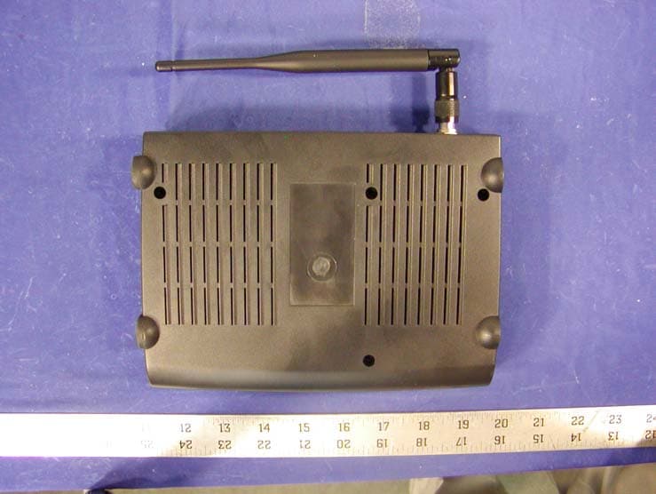
Click to zoom
Application Details
- Equipment Class
- DSS - Part 15 Spread Spectrum Transmitter
- Date of Grant
- Jun 25, 2002
- Application Purpose
- Original Equipment
- Date of Application
- Jun 25, 2002
- Equipment Note
- 802.11b Wireless LAN Router
- Frequency Range
- 2412.00000000 - 2472.00000000
- Company
- Arescom, Inc.
- Country
- United States
Documents & Files
Document Text
Text extracted from the exhibit documents filed with the FCC. Open a document above to read the original.
Users Manual
ARESCOM, INC. 3541 Gateway Blvd. Fremont, CA 94538 USA http://www.arescom.com AresGate 2000/2000S AresGate 2000/2000SAresGate 2000/2000S AresGate 2000/2000S 802.11b Wireless LAN Router 802.11b Wireless LAN Router802.11b Wireless LAN Router 802.11b Wireless LAN Router Software User’s Guide Software User’s GuideSoftware User’s Guide Software User’s Guide Ve r s i o n 2 . 0 June 2002 COPYRIGHT & TRADEMARKS Copyright © 2002 ARESCOM, Inc. All rights reserved. ARESCOM, ARESCOM CDS are trademarks of ARESCOM, Inc. Microsoft and Windows 95/98/2000/NT/Me are registered trademarks of Microsoft Corporation. Pentium is a registered trade- mark of Intel Corporation. All other trademarks and registered trademarks belong to their respective companies. ARESCOM, Inc. has the right to make revisions and to change the contents of this document without any obligation to provide prior notice of such revisions and changes. ARESCOM has the right to make improvements or changes in the product(s) and/or software(s) described in this documenta- tion. All specifications are subject to changes without notice. No part of this documentation or software may be reproduced or distributed in any form without prior written permission from ARESCOM, Inc. AG2000Series Software User’s GuideJune 2002iii Table of Contents Table of Contents CHAPTER 1OVERVIEW 1.1Introduction .........................................................................................................................1 1.2Features ...............................................................................................................................1 1.3Package Includes .................................................................................................................1 1.4Minimum System Requirements ........................................................................................2 1.5Network Scenario ...............................................................................................................2 1.5.1Installing a Single AG2000 ................................................................................ 2 1.5.2Installing Multiple AG2000s .............................................................................. 3 CHAPTER 2HARDWARE INSTALLATION 2.1Panel Information ...............................................................................................................5 2.1.1AresGate 2000 - Front Panel ............................................................................. 5 2.1.2AresGate 2000 - Back Panel .............................................................................. 6 2.1.3AresGate 2000S - Front Panel ........................................................................... 6 2.1.4AresGate 2000S - Back Panel ............................................................................ 7 2.2Location & Placement ........................................................................................................7 2.3Setup Instructions ...............................................................................................................8 CHAPTER 3BEFORE YOU START CHAPTER 4SOFTWARE CONFIGURATION 4.1Open Your Browser ..........................................................................................................11 4.2Basic - SETUP ..................................................................................................................12 4.2.1ISP Settings ....................................................................................................... 12 4.2.2Cable Modem .................................................................................................... 13 4.3Basic - WIRELESS ...........................................................................................................14 4.4Basic - AUTHENTICATION ...........................................................................................16 4.5Basic - DHCP ....................................................................................................................18 4.5.1Reserved IP Table ............................................................................................. 19 4.6Basic - USER STATUS ....................................................................................................20 4.6.1Current Log-on User Status ............................................................................. 20 4.7Basic - STATUS ...............................................................................................................21 4.8Advanced - ADMINISTRATION ....................................................................................23 4.8.1Administration .................................................................................................. 23 4.8.2NAT (Network Address Translation) ................................................................ 24 4.9Advanced - PORT MAPPING ..........................................................................................25 4.9.1Current Port Mapping Table ............................................................................ 25 4.9.2Add Port Mapping Entry .................................................................................. 25 4.9.3Delete Port Mapping Entry .............................................................................. 26 4.10Advanced - IP ROUTING ................................................................................................27 ivAG2000Series Software User’s Guide 4.10.1Current IP Routing Table ................................................................................. 27 4.10.2Add Route ......................................................................................................... 27 4.10.3Delete Route ..................................................................................................... 27 4.11Advanced - SNMP .........................................................................................…
Text truncated - open the document above for the full version.
Block Diagram
AA BB CC DD EE 4 4 3 3 2 2 1 1 ARESCOM AG2000S/AG2000 PCB P/N: 109000000229 Rev 1.0:CREATED ON MAR/21/2002 Motorola MPC 850 CPU SINGLE BOARDWLAN AP + 10BTWLAN VERSION UPDATE HISTORY : AG2000 WITH 10BT LAN PAGE 3 BLOCK DIAG RAM: POWER LED PAGE 7 TRANSFORMER WAN / LAN +3.3V PAGE 6 +2.5V +5V SWITCH CIRCUIT PAGE 4 PROGRAMMING PAGE 10 ETHERNET 1M X 8 2X1MX16SDRAM PAGE 9 RJ45 5 PORT 10/100 PAGE 5 Motorola MPC850SAR CPU EEPROM PAGE 5 4 PORTS ETHERNET JACKS LED LATCH FLASH PAGE 2 for WLAN SDRAM BUS PCMCIA UNMANAGED PAGE 6 EPB BUS GPIO PAGE 9 PAGE 5 PROGRAMMING SNI C). CS4: SDRAM.B). CS2: LED.A). CS0: FLASH. 1. CHIP SELECT ASSIGMENTS:2. LED ASSIGMENTS: (ACTIVE LOW) C). MD2: WAN LINK/ACT(GREEN).B). MD1: RESERVED. MPC 850 SAR PIN ASSIGMENTS: E). MD4: WLAN LINK/ACT(GREEN).A). MD0: DIAG (AMBER).D). MD3: LAN LINK/ACT(GREEN). TRANSFORMERJACK-RJ45 ETHERNET PHY ESD PROTECT CIRCUIT 1 PORT 10BT LAN PAGE 7 PAGE 7 OPTIONAL: ONE PORT LAN AG2000S WITH 4 PORTS 10/100BT Rev 2.0:CREATED ON MAY/21/ 2002 1. Change FB1 to FB5 to 0R/1206 for EMI. SYSTEM CLOCK= 48MHzCLOCK= 4MHz JACK-RJ45ESD PROTECT CIRCUIT PAGE 8 ETHERNET PHY PAGE 8 CLOCK= 20MHzCLOCK= 20MHz1 PORT 10BT WAN CLOCK= 25MHz PAGE01_HEADER 2.0 AG2000Arescom, Inc. C 110 Monday, June 24, 2002 TitleSize Document Number Rev Date: Sheet of
External Photos
APPENDIX C - EUT EXTERNAL PHOTOGRAPHS Chassis - Front View Chassis - Rear View Chassis - Top View Chassis - Bottom View Power Adapter Top View
ID Label/Location Info
APPENDIX A - FCC ID LABELING AND WARNING STATEMENT FCC ID Label Proposed Label Location on EUT Bottom Side of EUT/Proposed Label Location FCC Warning Statement The device shall bear the following FCC statement. If the EUT is so small or for such use that it is not practicable to place the statement on it, the statement shall be placed in a prominent location in the instruction manual or pamphlet supplied to the user or, alternatively, shall be placed on the container in which the device is marketed. However, the FCC identifier or the unique identifier, as appropriate, must be displayed on the device. “This device complies with Part 15 of the FCC Rules. Operation is subject to the following two conditions: (1) this device may not cause harmful interference, and (2) this device must accept any interference received, including interference that may cause undesired operation.” FCC ID: PT2AG2000S This device complies with Part 15 o the FCC Rules. Operation is subject to the following two conditions: (1) this device may not cause harmful interference, and (2) this device must accept any interference received, including interference that may cause undesired operation. Caution: To comply with FCC RF exposure requirements, a separation distance of at least 8 inches (20cm) must be maintained between the antenna of this and all persons. 2.1875" 1.0"
Internal Photos
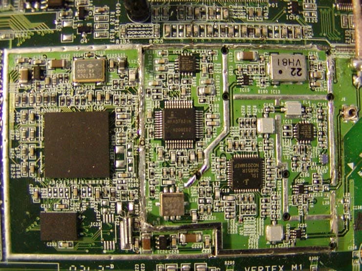
APPENDIX C - EUT INTERNAL PHOTOGRAPHS Main Board - Component View Main Board - Solder View RF Board - Component View
Operational Description
AG2000Series Software User’s GuideJune, 200235 APPENDIX A:TECHNICAL SPECIFICATIONS A.1 Hardware Specifications WAN Interface •One Ethernet 10BaseT (IEEE 802.3) port (RJ-45). LAN Interface •AG2000: One 10BaseT (IEEE 802.3) Ethernet port (RJ-45). •AG2000S: Four 10/100 BaseT Ethernet switching ports (RJ-45). Wireless LAN Interface •IEEE 802.11b High Rate compliant. •Operating in the unlicensed 2.4GHz ISM band. •Operation Frequency/Channels (Either one below): - North America/FCC: 2.412~2.462 GHz (11 channels). - Europe/ETS: 2.412~2.472 GHz (13 channels). - Japan TELEC: 2.412~2.472 GHz (14 channels). •Modulation Technique: Direct Sequence Spread Spectrum (CCK, DQPSK, DBPSK). •Dynamic Rate Shifting: 11, 5.5, 2 and 1Mbps. •Media Access Protocol: CSMA/CA with ACK. •Security Management: 40-bit, 128-bit WEP (wired equivalent privacy) Encryption. •Maximum Output Power: 17dBm (50mW). Antenna •Removable 3-dBi diversity high gain dipole antenna. LEDs AG2000 •PWR •DIAG •WAN •LAN •WLAN AG2000s •PWR •DIAG •WAN 36June, 2002AG2000Series Software User’s Guide •LAN/LINK 1 - 4 •LAN/ACT 1 - 4 •WLAN Mechanical •Dimensions: 8” (w) x 5.75” (d) x 1.5” (h). •Weight: 1.5 lbs. Operating Environment •Operating temperature: 0°C to 40°C (32°F to 104°F). •Operating humidity: 0% to 95% non-condensing. Power External AC Power Adapter •Input: 230V 85mA or 120V 155mA, 47-60 Hz. •Output: 13.5V AC, 1A. •Power consumption: 8.5 watts nominal. Compliance / Regulatory •EMI: FCC Part15 Class B & Part 15C, CE EN55022 Class B. •Telecom: FCC Part 68. •Wi-Fi Certified. •Immunity: CE EN55024. •Safety: CE EN60950 AG2000Series Software User’s GuideJune, 200237 A.2 Software Features Authentication 802.1x Authentication •EAP/ MD5 (PPP Extensible Authentication Protocol, RFC 2284) mechanism for authentica- tion. •RADIUS server (RFC2865, RFC 2869). •RADIUS Accounting (RFC 2866). MAC Authentication •Authentication through the client's MAC address (RFC 2865). Web Re-direction •Unauthorized users automatically re-direct to a configured web page for registration. Radio Control Automatic Channel Selection •Automatically selects the optimal channel for minimal radio interference from other nearby APs. •ON/OFF selectable. Date Rate Selection •Manually selects data rates from 1Mbps, 2Mbps, 5.5Mbps and 11Mbps. Roaming •IEEE 802.11b High Rate compliant. •Automatic account roll-over. RADIUS •Up to two RADIUS authentication servers: Authentication and Accounting Servers. •Configured port number and accounting port number. Routing •TCP/IP (RFC791, RFC792, RFC793), ARP (RFC826). •Static routing on the LAN and/or WAN. •Dynamic routing protocol supports RIP1 (RFC1058), RIP2 (RFC1723). 38June, 2002AG2000Series Software User’s Guide DHCP •DHCP server (RFC 2131,RFC2132): automatic to assign IP address, Subnet Mask, Gateway, and DNS to workstations. •DHCP relay. •DHCP pass-through. Bridging •IEEE 802.1d-compliant transparent bridging between wireless interface and wired LAN inter- face. •Bridge Filters – Up to 32 filter entries, MAC address criteria setup. •Supports up to 510 MAC learning addresses. •RFC1483-bridged (LLC or VC MUX encapsulation) over ATMPVC. Internet Access Sharing •NAT/PAT (RFC1631) proxy supports unlimited multi-user sharing via Ethernet LAN. •NAT (Network Address Translation) supports PAT (Port Address Translation) for Web server hosting, multimedia applications, and Internet gaming. •NAT supports PPTP and IPSec VPN pass through. Security •IEEE 802.1X port-based network access control. •PAT (RFC1334), CHAP (RFC1994), and MS-CHAP user authentication. •Username and password control for network management access. •WEP (Wired Equivalent Privacy): 40/128-bit encryption keys and SSID. Network Management Access Interfaces •Web browser-based manager. •Command Line Interface through RS-232 console port. •Telnet support. •SNMP (Simple Network management Protocol): RFC1157. SNMP •MIB II (RFC1213). •Wireless MIB (IEEE 802dot11). •Private MIB. •SNMP traps (RFC1215). AG2000Series Software User’s GuideJune, 200239 Functions •Device configuration. •Firmware upgrade available via FTP or locally. •Real time status display and event report and Syslog. •Remote reboot (hardware) and reset. NOTE: Product specifications are subject to change without prior notice. 40June, 2002AG2000Series Software User’s Guide AG2000Series Software User’s GuideJune, 200239 APPENDIX B:CABLE AND CONNECTORS B.1 Connector Specifications B.1.1 10/100 Ports The 10/100 Ethernet ports use standard RJ-45 connectors and Ethernet pinouts with internal crossovers, as shown by an X in the port name. These ports have their trans- mit (Tx) and receive (Rx) signals internally crossed so that a straight-through Ether- net cable and an adapter can be attached to the port. The figure below shows the pinouts. Figure B.110/100 Ethernet Port Pinout B.2 Cable Specification B.2.1 RJ-45 The pin assignment is as follows: RJ-45 to RJ-45 Straight-through Ethernet Cable: RJ-45 to RJ-45 Crossover Ethernet Cable: PinLabel1 2 3 4 5 6 7 8 1Tx+ 2Tx- 3Rx+ 4NC 5NC 6Rx- 7NC 8NC 40June, 2002AG2000Series Software User’s Guide AG2000Series Software User’s GuideJune, 200243 APPENDIX C:GLOSSARY 802.1XAn IEEE standard for local and metropolitan area networks, called Port-based Network Access Control. It is used to securely establish an authenticated association between the client and the AP. AP (Access Point)A hardware device, or software used in conjunction with a computer, that serves as a communications “hub” for wireless clients and provides a connection to a wired LAN. An AP can double the range of wireless clients and provide enhanced security. Ad-Hoc ModeA client setting that provides independent peer-to-peer connectivity in a wireless LAN. An alternative set-up is where PCs communicate with each other through an AP (see also Infrastructure Mode). BandwidthThe amount of data that can be transmitted by the network “information highway”, used as an indication for speed of data transmission. An Ethernet link is capable …
Text truncated - open the document above for the full version.
Schematics
AA BB CC DD EE 4 4 3 3 2 2 1 1 ARESCOM AG2000S/AG2000 PCB P/N: 109000000229 Rev 1.0:CREATED ON MAR/21/2002 Motorola MPC 850 CPU SINGLE BOARDWLAN AP + 10BTWLAN VERSION UPDATE HISTORY : AG2000 WITH 10BT LAN PAGE 3 MPC 850 SAR BLOCK DIAGRAM: POWER LED PAGE 7 TRANSFORMER WAN / LAN +3.3V PAGE 6 +2.5V +5V SWITCH CIRCUIT PAGE 4 PROGRAMMING PAGE 10 ETHERNET 1M X 8 2X1MX16SDRAM PAGE 9 RJ45 5 PORT 10/100 PAGE 5 MotorolaMPC850SAR CPU EEPROM PAGE 5 4 PORTS ETHERNET JACKS LED LATCH FLASH PAGE 2 for WLAN SDRAM BUS PCMCIA UNMANAGED PAGE 6 EPB BUS GPIO PAGE 9 PAGE 5 PROGRAMMING SNI C). CS4: SDRAM.B). CS2: LED.A). CS0: FLASH. 1. CHIP SELECT ASSIGMENTS:2. LED ASSIGMENTS: (ACTIVE LOW) C). MD2: WAN LINK/ACT(GREEN).B). MD1: RESERVED. MPC 850 SAR PIN ASSIGMENTS: E). MD4: WLAN LINK/ACT(GREEN).A). MD0: DIAG (AMBER).D). MD3: LAN LINK/ACT(GREEN). TRANSFORMERJACK-RJ45 ETHERNET PHY ESD PROTECT CIRCUIT 1 PORT 10BT LAN PAGE 7 PAGE 7 OPTIONAL: ONE PORT LAN AG2000S WITH 4 PORTS 10/100BT Rev 2.0:CREATED ON MAY/21/ 2002 1. Change FB1 to FB5 to 0R/1206 for EMI. SYSTEM CLOCK= 48MHzCLOCK= 4MHz JACK-RJ45ESD PROTECT CIRCUIT PAGE 8 ETHERNET PHY PAGE 8 CLOCK= 20MHzCLOCK= 20MHz1 PORT 10BT WAN PAGE01_HEADER 2.0 AG2000Arescom, Inc. C 110 Tuesday, June 04, 2002 TitleSize Document Number Rev Date: Sheet of AA BB CC DD EE 4 4 3 3 2 2 1 1 FULL SPEED USB DISABLE MODE CLOCK Select: 1. MODCK[1,2]=[0,1] : SPLL input is OSCM. 2. MODCK[1,2]=[1,1] : SPLL input is EXTCLK. PAGE02_MPC850SAR 2.0 AG2000Arescom, Inc. 210 Tuesday, June 04, 2002 TitleSize Document Number Rev Date: Sheet of VFLS0BS_AB3IRQ4 TRSTN TMS CS0NCS1N VDDSYN PIN_D8SRESETNBURSTNPIN_C9PIN_G16SYSCLKPIN_B10 TSN PIN_E12GPL0 PORESETN RSTCONFN CS4NPIN_C16GPL2 TAN CS2N BIN MODCK1MODCK2PIN_D10VFLS1BS_AB1PIN_D15PIN_C14 XFC BS_AB2PIN_D5PIN_E6HRESETNPIN_C10GPL3PIN_E9 TEAN BS_AB0PIN_E8RWN CS3N PIN_B14 GPL1PIN_D13 IRQ2 PIN_F16BGN IRQ6 BRNIRQ7IRQ1PIN_E14IRQ0BBN IRQ2 USBTXN USBTXP USBOEN USBRXN USBRXP USBRXD UTO_TCAV UTO_RXEN UTO_SOCRXCLAV UTO_TXEN XTAL AA SYSCLK_O SYSCLK MA11 MA9MA8 MA6MA7 UTL_AD5RDUTL_AD7UTO_D2UTO_D3UTO_D7UTL_AD1UTL_AD3UTO_D6UTL_AD4UTO_D4UTL_AD6WRUTL_AD0UTO_D5UTL_AD2UTO_CLKUTL_CSNPRSTNAUTO_D1ALE EXTCLK MA[6..31]DQ[0..31] PIN_E4MA26MA15 TRSTN GPL1 GPL2 GPL3 XFC CON_RXD1 DQ0MA10 BS_AB2 HRESETN XTAL UTL_AD6UTO_D5UTO_TCAVPIN_R14UTO_RCAVUTL_CSN DQ31DQ19DQ9MA12 BIN PIN_F16 PIN_C9 PIN_E8 USBOEN DQ24DQ11DQ6MA28MA11 USBTXNUTL_AD5 DQ25DQ8DQ7 VDDSYN UTL_AD6 MA17 TEAN RWN DSCK BBN PIN_E14 CS4N CS3N CS2N BS_AB0 PIN_C14 PIN_B10 MODCK2 UTL_AD2UTO_D7UTL_WRN DQ13 UTL_AD7 MA23MA16MA8 BURSTN PIN_G16 PORESETN SYSCLK_O PIN_PD8UTO_D3 DQ30 IRQ2 PIN_B14 BS_AB1 GPL0 VFLS0 PIN_D10 UTO_RXENPIN_R7ETHER_COLCON_TXD1PIN_R16 DQ22MA30MA22 PIN_C16 PIN_D13 PIN_D8 UTO_D0 DQ26DQ16DQ14MA13MA6 TMSDSDI BGN IRQ6 PIN_C10 DQ23DQ3 ETHER_TCLK1ETHER_RCLK1 MA29 CS0N SRESETN UTL_AD7USBRXPUTL_AD1 DQ18DQ15DQ5DQ2MA31MA21MA18 TAN IRQ1 MODCK1 ID_DATAUTO_D4UTO_CLKUTL_AD4UTL_ALEUTL_RDNSRA_RSTNPIN_R15 DQ10MA27MA25MA7 PIN_E12 RSTCONFN EXTCLK UTO_D1ETHER_CRS DQ28DQ27DQ17PIN_D3MA24 USBRXD EXTAL MA20 TSN VDDSYN BRN CS1N PIN_D5 ETHER_RDUTO_D6UTO_TXENUTO_D2USBRXN PIN_E5PIN_D4DQ29DQ20DQ1 IRQ4 IRQ0 VFLS1 PIN_E9 PIN_U5ETHER_TXENUTL_AD0 DQ21DQ12DQ4MA19MA14 DSDO IRQ7 PIN_D15 BS_AB3 EXTAL UTL_AD3UTO_SOC MA9 PIN_E6 USBTXP CD2_BN 10CE1_BN 10 RECVR 9 VFLS0 10CD1_BN 10 PORESETN 9 SRESETN 10 RXCLAV 10 BS_AB2/OEN 4,10 MA[6..31] 3,4,10 BS_AB3/WEN 4,10GPL2 4 ALE PIN_E5 10 BURSTN 10 DSCK 10 TEAN 10 BS_AB1/IOWRN 4,10PIN_E6 10 DSDI 10 IRQ4 10 ETHER_CRS 5,7 ETHER_TD 5,7 POE_B 10 PIN_D4 10PIN_E4 10 ETHER_TXEN 5,7 UTL_CSN CS4N 4GPL1 3,4CE2_BN 10 BIN 10 STSCHG_BN 10 CON_RXD1 10 SYSCLK 4SPKR_BN 10GPL0 4 DQ[0..31] 4 CON_TXD1 10 ETHER_LINK 5,7 VFLS1 10REGN 10PIN_C9 10 DSDO 10 PIN_C14 10 TAN 10 PIN_D3 10 CS2N 9 PRSTNA GPL3 4 RDETHER_COL 5,7 ID_DATA 3 IREQ_BN 10CS1N 10 ETHER_RSTN 5 WAIT_BN 10 PIN_B14 10 PIN_D13 10IOIS16BN 10 ETHER_TCLK 5,7 BS_AB0/IORDN 3,4,10 WRUSBRXN HRESETN 10CS0N 3,10RESET_B 10 ETHER_RD 5,7 PIN_E12 10 TSN 10 RWN 10 HINTNA PIN_F16 10BBN 10IRQ7 10IRQ0 10BRN 10PIN_E14 10 FRZ 10 IRQ1 10BGN 10 ETHER_RD_W 8 ETHER_LINK_W 8 ETHER_CRS_W 8 ETHER_COL_W 8 ETHER_SCL 5 ETHER_SDA 5 ETHER_TXEN_W 8 ETHER_TD_W 8 ETHER_RCLK 7 ETHER_RCLK_W 8 USBRXP ETHER_TCLK_W 8 +3.3V +3.3V +3.3V +3.3V +3.3V +3.3V+3.3V+3.3V +3.3V +3.3V +3.3V +3.3V +3.3V +3.3V +3.3V +3.3V +3.3V R60 0R R256 10K R244 0R C2390.1uF R197 4.7K RP810K 1234 5 6789 10 01020304 C 06070809 C R239 4.7K C2340.1uF TP34 C2320.1uF R25010M R246 33 RP910K 1234 5 6789 10 01020304 C 06070809 C C2370.1uF C2420.1uF R195 OPEN C2310.1uF R2510R C2380.1uF + C22710uF,16V R254 1K R64 0R Y2 4MHz R62 33 R2434.7K + C22810uF,16V R253 10K + C222 10uF,16V R2424.7K R63 33 R257 1K C2400.1uF RP710K 1234 5 6789 10 01020304 C 06070809 C TP31 R56 0R TP33 R200 OPEN R2521K TP30 R57 0R TP32 C2350.1uF C2410.1uF R240 4.7K R58 0R C2230.1uF C197 OPEN\22PF R59 0R R61 0R + C22910uF,16V R205 OPEN C2330.1uF C24547PF C198OPEN R255 1K R65 33 + C22610uF,16V R241 0R C2306800PF R66 0R C2360.1uF R248 10K L20 FB/S8 R196 4.7K C24656PF R247 0R R249 150 R201 OPEN MPC850 PBGA (JEDEC) PRELIMINARY PART SYMBOL 04 MAY 98 U17 N2M2K3K2M3J2G2F2N3L3L4L2N5N4K4K5J3L5J4H3H4G3J5M5G4H5F5M4G5F3E3F4D4E5 R16R15U16U15R13 P12 U12U11 T10 T8 R8 P8 T6 T17 U17R14U14 T11 R10 T9 P9 U6 P7 R7U5 T5 U4R6 T4 P6 U3R5U2 T3T2 R3R4 P5 P15 T7 U7R9U9 U10 P11 T14T15T16 R17 C7 E7 E9 D8 D10 C10 B10 E8 D9 B9 C9 D5 E6 B7 E2 C3 B6 B5 C5 C6 D6 C4 D13 C14 E12 E15 D16 D17 F14 G14 E16 F17 E17 C16 D15 E13 B15 C15 B16 C17 E14 P4 P3 P2 B11 B12 D11 C12 R12 P13 T12T13 U13 U8 K17 H2 B8B3B2B4 C2 G16 F16 D14 C11 B14 E11 B13 D12 C13 E10 C8 B17D7F15K14P10P14R2R11N14P16P17N16M14N17N15M15M16M17L15L14H14L16K16K15H15J16J14J15G15L17H17J17H16G17 F6 F7 F8 F9 F10 F11 F12 F13 G6 G13 H6 H13 J6 J13 K7 K8 K9 K10 K11 K12 L7 L8 L9 L10 L11 L12 M7 M8 M9 M10 M11 M12 E4D3D2 G7 G8 G9 G10 G11 G12 H7 H8 H9 H10 H11 H12 J7 J8 J9 J10 J11 J12 K6 K13 L6 L13 M6 M13 N6 N7 N8 N9 N10 N11 N12 N13 D0D1D2D3D4D5D6D7D8D9 D10D11D12D13D14D15D16D17D18D19D20D21D22D23D24D25D26D27D28D29D30D31 DP0/IRQ3 DP1/IRQ4 PB[30]/SPICLK/TXD3PB[29]/SPIMOSI/RXD3P…
Text truncated - open the document above for the full version.
Test Report
Note: This test report is specially limited to the above client company and product model only. It may not be duplicated without prior written consent of Bay Area Compliance Laboratory Corporation. This report must not be used by the client to claim product endorsement by NVLAP or any agency of the U.S. Government. FCC PART 15 SUBPART C EMI MEASUREMENT AND TEST REPORT For Arescom, Inc. 3541 Gateway Blvd. Fremont, CA 94538 FCC ID: PT2AG2000S June 21, 2002 This Report Concerns: Original Report Equipment Type: 802.11b Wireless LAN Router Test Engineer: Benjamin Jing Report No.: R0205162 Test Date: May 16, 2002 Reviewed By: Jeff Lee Prepared By: Bay Area Compliance Laboratory Corporation 230 Commercial Street Sunnyvale, CA 94085 Tel: (408) 732-9162 Fax: (408) 732 9164 Arescom, Inc. FCC ID: PT2AG2000S Report # R0205162Rpt Page 2 of 26 FCC Part 15.247 TABLE OF CONTENTS 1 - GENERAL INFORMATION..................................................................................................................................4 1.1 PRODUCT DESCRIPTION FOR EQUIPMENT UNDER TEST (EUT) ..............................................................................4 1.2 OBJECTIVE.............................................................................................................................................................4 1.3 TEST METHODOLOGY............................................................................................................................................4 1.4 TEST FACILITY.......................................................................................................................................................4 1.5 TEST EQUIPMENT LIST...........................................................................................................................................5 1.6 LOCAL SUPPORT EQUIPMENT LIST AND DETAILS...................................................................................................5 1.7 EXTERNAL CABLES LIST AND DETAILS..................................................................................................................5 2 - SYSTEM TEST CONFIGURATION AND REQUIREMENT............................................................................6 2.1 DESCRIPTION OF TEST CONFIGURATION................................................................................................................6 2.2 EQUIPMENT MODIFICATION...................................................................................................................................6 2.3 CONFIGURATION OF TEST SYSTEM.........................................................................................................................6 2.4 TEST SETUP BLOCK DIAGRAM...............................................................................................................................6 3 - SUMMARY OF TEST RESULTS..........................................................................................................................7 4 - CONDUCTED OUTPUT POWER.........................................................................................................................8 4.1 STANDARD APPLICABLE........................................................................................................................................8 4.2 MEASUREMENT PROCEDURE..................................................................................................................................8 4.3 MEASUREMENT RESULT........................................................................................................................................8 4.4 TEST EQUIPMENT...................................................................................................................................................8 5 - SPURIOUS EMISSION.........................................................................................................................................10 5.1 STANDARD APPLICABLE......................................................................................................................................10 5.2 MEASUREMENT PROCEDURE................................................................................................................................10 5.3 MEASUREMENT DATA..........................................................................................................................................10 6 - 6 DB BANDWIDTH OF EMISSIONS .................................................................................................................14 6.1 STANDARD APPLICABLE......................................................................................................................................14 6.2 MEASUREMENT PROCEDURE................................................................................................................................14 6.3 MEASUREMENT DATA..........................................................................................................................................14 7 - 100 KHZ BANDWIDTH OF BAND EDGES ......................................................................................................16 7.1 STANDARD APPLICABLE......................................................................................................................................16 7.2 MEASUREMENT PROCEDURE................................................................................................................................16 7.3 TEST RESULTS.....................................................................................................................................................16 8 - POWER DENSITY ................................................................................................................................................18 8.1 STANDARD APPLICABLE.......................................................................................................…
Text truncated - open the document above for the full version.
Test Setup Photos
APPENDIX B - TEST SETUP PHOTOGRAPHS Conducted Emission - Front View Conducted Emission - Rear View Radiated Emission - Front View Radiated Emission - Rear View
Contact Information
Applicant
James Lu(Senior Hardware Manager)
Test Firm
Bay Area Compliance LaboratoryJohn Chan
Technical Specifications
| # | Rule Parts | Frequency Range | Power Output |
|---|---|---|---|
| 1 | 15C | 2.41 GHz - 2.47 GHz | 43.00 mW |
Other Applications from Arescom, Inc.
PT2AG2560
Jun 27, 2002ADSL Wireless Router
Equipment Class
DSS - Part 15 Spread Spectrum Transmitter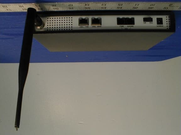
PT2AG1000PRO
Oct 22, 2001AresGate 1000 Wireless Router
Equipment Class
DSS - Part 15 Spread Spectrum Transmitter