PT3-B00YZLED LAMP
Misfit, Inc.
Click to zoom
Application Details
- Equipment Class
- DTS - Digital Transmission System
- Date of Grant
- Mar 05, 2015
- Application Purpose
- Original Equipment
- Date of Application
- Mar 04, 2015
- Equipment Note
- LED LAMP
- Frequency Range
- 2402.00000000 - 2480.00000000
- Company
- Misfit, Inc.
- Country
- United States
Documents & Files
Document Text
Text extracted from the exhibit documents filed with the FCC. Open a document above to read the original.
Users Manual
BOLT ™ QUICK START GUIDE For more detailed Bolt information visit: www.misfit.com/go WIRELESSLY CONNECTED SMART BULB BOLT 1 PACKAGE INCLUDES: BOLT ™ QUICK START GUIDE Misfit Bolt Bulb x 1Quick Start Guide x 1 2 SPECIFICATIONS Voltage: Universal power 100-240V 50/60Hz Wattage: 13 Watts at Maximum Brightness Lumens: 800+ Lumens (60W Equivalent) Lifetime: Over 20 Years (3 hours of usage per day, 7 days a week) Connection: Bluetooth Low Energy 4.0 Operating Temperature: 0 - 45 °C Screw Fitting: E26 Technology: LED 3 CAUTION • This product is not intended for use in emergency light fixtures or exit signs. • Before use, ensure that the power voltage of the light socket is compatible with the bulb. Incompatible voltages may result in a safety issue. • Do not dismantle the bulb. • To reduce the risk of overheating and possible damage to other equipment do not install inside an enclosure that traps heat. Install the bulb where air can move freely. • To avoid electrical shock or burn, do expose the bulb to water or touch with wet hands unless unscrewed and/or unpowered • Indoor use only. Not for use in wet locations such as bathrooms or outdoors. • Before removing the bulb, turn o power and let the bulb cool to avoid electric shock or burn. • Not a toy, not for children • Do not place on hot surfaces • For safety, do not open the device, which also voids warranty • Use the bulb only in a socket rated compatible (voltage & wattage) • Always dispose or recycle electrical devices in accordance with local disposal laws. • After use, the bulb may be hot to the touch. Use caution. NOTICE • Not for use with dimmer switches. App required for dimming or color change. • The aluminum portion of the bulb will not cause electrocution and is safe to touch. 4 CAUTION • This product is not intended for use in emergency light fixtures or exit signs. • Before use, ensure that the power voltage of the light socket is compatible with the bulb. Incompatible voltages may result in a safety issue. • Do not dismantle the bulb. • To reduce the risk of overheating and possible damage to other equipment do not install inside an enclosure that traps heat. Install the bulb where air can move freely. • To avoid electrical shock or burn, do expose the bulb to water or touch with wet hands unless unscrewed and/or unpowered • Indoor use only. Not for use in wet locations such as bathrooms or outdoors. • Before removing the bulb, turn o power and let the bulb cool to avoid electric shock or burn. • Not a toy, not for children • Do not place on hot surfaces • For safety, do not open the device, which also voids warranty • Use the bulb only in a socket rated compatible (voltage & wattage) • Always dispose or recycle electrical devices in accordance with local disposal laws. • After use, the bulb may be hot to the touch. Use caution. NOTICE • Not for use with dimmer switches. App required for dimming or color change. • The aluminum portion of the bulb will not cause electrocution and is safe to touch. 5 CAUTION • This product is not intended for use in emergency light fixtures or exit signs. • Before use, ensure that the power voltage of the light socket is compatible with the bulb. Incompatible voltages may result in a safety issue. • Do not dismantle the bulb. • To reduce the risk of overheating and possible damage to other equipment do not install inside an enclosure that traps heat. Install the bulb where air can move freely. • To avoid electrical shock or burn, do expose the bulb to water or touch with wet hands unless unscrewed and/or unpowered • Indoor use only. Not for use in wet locations such as bathrooms or outdoors. • Before removing the bulb, turn o power and let the bulb cool to avoid electric shock or burn. • Not a toy, not for children • Do not place on hot surfaces • For safety, do not open the device, which also voids warranty • Use the bulb only in a socket rated compatible (voltage & wattage) • Always dispose or recycle electrical devices in accordance with local disposal laws. • After use, the bulb may be hot to the touch. Use caution. NOTICE • Not for use with dimmer switches. App required for dimming or color change. • The aluminum portion of the bulb will not cause electrocution and is safe to touch. STRUCTURE Shade Body Wireless Signal Area Holder 6 CAUTION • This product is not intended for use in emergency light fixtures or exit signs. • Before use, ensure that the power voltage of the light socket is compatible with the bulb. Incompatible voltages may result in a safety issue. • Do not dismantle the bulb. • To reduce the risk of overheating and possible damage to other equipment do not install inside an enclosure that traps heat. Install the bulb where air can move freely. • To avoid electrical shock or burn, do expose the bulb to water or touch with wet hands unless unscrewed and/or unpowered • Indoor use only. Not for use in wet locations such as bathrooms or outdoors. • Before removing the bulb, turn o power and let the bulb cool to avoid electric shock or burn. • Not a toy, not for children • Do not place on hot surfaces • For safety, do not open the device, which also voids warranty • Use the bulb only in a socket rated compatible (voltage & wattage) • Always dispose or recycle electrical devices in accordance with local disposal laws. • After use, the bulb may be hot to the touch. Use caution. INSTALLATION 1 Make sure the light socket power is o . Screw the bulb into the light socket. Turn on the power. Make sure the light bulb is not in a fully-enclosed fixture. NOTICE • Not for use with dimmer switches. App required for dimming or color change. • The aluminum portion of the bulb will not cause electrocution and is safe to touch. ON 7 Download and install the Misfit or Misfit Home application onto your mobile device. Enable Bluetooth on your mobile device. 23 8 Launch the app and follow instructions in the app. 4 For more detailed Bolt information visit: www.misfit.com/go 9 FCC COMPLIANCE STATEM…
Text truncated - open the document above for the full version.
Cover Letter(s)
SCS-F18: Project and Product Certification Representative Authorization Letter Page 1 of 2 Rev 5.0 775 Montague Expressway Milpitas, CA 95035 Tel: 408-526-1188 Fax: 408-526-1088 Email: [email protected] Project and Product Certification Representative Authorization Letter Reason for Amendment (current / obsolete) Revision History Approved Date From To Initial Release (obsolete) 1.0 1.0 Nov-14-2006 Revised wording (obsolete) 1.0 2.0 Sept–25-2007 Updated company template (obsolete) 2.0 3.0 Jan-31-2012 Updated letter information (obsolete) 3.0 4.0 May-23-2014 Added FCC ID field (current) 4.0 5.0 Sept 16 2014 SCS-F18: Project and Product Certification Representative Authorization Letter Page 2 of 2 Rev 5.0 Misfit Wearables Corporation 2015-1-30 To: SIEMIC, INC. 775 Montague Expressway, Milpitas, CA 95035 USA Dear Sir/Madam, Re: Product Certification Representative Authorization Letter We, Misfit Wearables Corporation , hereby authorize SIEMIC, Inc. to act as a Certification Body for certifying for the following project(s): LED LAMP Model Number: B00YZ Sincerely, Sonny Vu / CEO E-mail: [email protected] Phone: 6176426226 Fax: 6502413805 Address: 5 Brookdale Road., Salem, New Hampshire 03079,United States FCC ID: PT3-B00YZ
Cover Letter(s)
SCS-F19: Confidentiality Request Letter Page 1 of 2 Rev 3.0 775 Montague Expressway Milpitas, CA 95035 Tel: 408-526-1188 Fax: 408-526-1088 Email: [email protected] Confidentiality Request Letter Reason for Amendment (current / obsolete) Revision History Approved Date From To Initial Release (obsolete) 1.0 1.0 Nov-14-2006 Adding CFR 2.459 (obsolete) 1.0 2.0 August – 11 - 2008 Updated company template & Added text box (current) 2.0 3.0 Jan-31-2012 SCS-F19: Confidentiality Request Letter Page 2 of 2 Rev 3.0 Misfit Wearables Corporation 2015-1-30 To: Federal Communications Commission Authorization and Evaluation Division 7435 Oakland Mills Road Columbia, MD Subject: Permanent Confidentiality Request for FCC ID: PT3-B00YZ We hereby request confidential treatment of information accompanying this application as outlined below: - Block Diagram - Schematics - Operational Description The above materials contain trade secrets and proprietary information not customarily released to the public. The public disclosure of these materials may be harmful to the applicant and provide unjustified benefits to its competitors. The applicant understands that pursuant to Section 0.457 & 0.459 of the Rules, disclosure of this application and all accompanying documentation will not be made before the date of the Grant for this application. Sincerely, signature Sonny Vu/ CEO E-mail: [email protected] Phone: 6176426226 Fax: 6502413805 Address: 5 Brookdale Road., Salem, New Hampshire 03079, United States
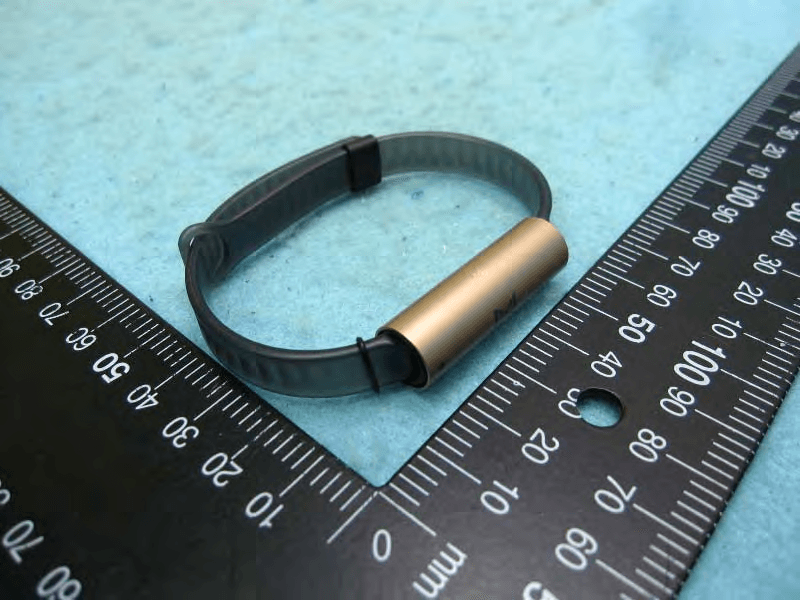
External Photos
External Photo
Internal Photos
Internal Photo Bluetooth Module Antenna
RF Exposure Info
FCC ID : PT3-B00YZ RF EXPOSURE EVALUATION According to FCC 1.1310: The criteria listed in the followi ng table shall be used to evaluat e the environment impact of human exposure to radio frequency(RF) Radiation as specified in §1.1307(b) Limits for Maximum Permissible Exposure (MPE) Frequency Range(MHz) Electric Field Strength(V/m) Magnetic Field Strength(A/m) Power Density(mW/cm 2 ) Average Time (A) Limits for Occupational/Control Exposures 300-1500 -- -- F/300 6 1500-100000 -- -- 5 6 (B) Limits for General Population/Uncontrol Exposures 300-1500 -- -- F/1500 6 1500-100000 -- -- 1 30 11.1 Friis transmission form ula: Pd= (Pout*G)\ (4*pi*R 2 ) Where Pd= Power density in mW/cm 2 Pout=output power to antenna in mW G= Numeric gain of the antenna relative to isotropic antenna Pi=3.1416 R= distance between observation point and center of the radiator in cm Pd the limit of MPE, 1mW/cm 2 . If we know the maximum gain of the nd total power input to the antenna, through the calculation, we will know the distance where the MPE limit is reached. 11.2 Measurement Result BT DTS Channel Freq. (MHz) modulation conducted power (mW) conducted power (dBm) Tune-up power (dBm) Max tune-up power (dBm) Antenna Gain Numeric Evaluation result (mW/cm2 ) Power density Limits (mW/cm2 ) 2402 GFSK 0.76 -1.190 -2dBm to 0dBm 0 0.63 0.00013 1 2440 GFSK 0.65 -1.870 -2dBm to 0dBm 0 0.63 0.00013 1 2480 GFSK 0.56 -2.521 -3dBm to -1dBm -1 0.63 0.00010 1
Test Report
TRF No.:FCC 15.247/A Page 1 of 41 Report No.: ES150122235E Ver.1.0 Access to the World FCC 47 CFR PART 15 SUBPART C CERTIFICATION TEST REPORT For LED LAMP MODEL No.: B00YZ FCC ID: PT3-B00YZ Trade Mark: MISFIT REPORT NO: ES150122235E ISSUE DATE: January 30, 2015 Prepared for MISFIT WEARABLES CORPORATION 5 Brookdale Road., Salem, New Hampshire 03079 Prepared by SHENZHEN EMTEK CO., LTD. Bldg 69, Majialong Industry Zone, Nanshan District, Shenzhen, Guangdong, China TEL: 86-755-26954280 FAX: 86-755-26954282 TRF No.:FCC 15.247/A Page 2 of 41 Report No.: ES150122235E Ver.1.0 Access to the World Table of Contents 1 TEST RESULT CERTIFICATION ............................................................................................................. 3 2 EUT TECHNICAL DESCRIPTION ........................................................................................................... 4 3 SUMMARY OF TEST RESULT ................................................................................................................ 5 4 TEST METHODOLOGY ........................................................................................................................... 6 4.1 GENERAL DESCRIPTION OF APPLIED STANDARDS ...................................................................... 6 4.2 MEASUREMENT EQUIPMENT USED ................................................................................................... 6 4.3 DESCRIPTION OF TEST MODES .......................................................................................................... 7 5 FACILITIES AND ACCREDITATIONS ..................................................................................................... 8 5.1 FACILITIES ................................................................................................................................................. 8 5.2 LABORATORY ACCREDITATIONS AND LISTINGS ............................................................................ 8 6 TEST SYSTEM UNCERTAINTY .............................................................................................................. 9 7 SETUP OF EQUIPMENT UNDER TEST ............................................................................................... 10 7.1 RADIO FREQUENCY TEST SETUP 1 .................................................................................................. 10 7.2 RADIO FREQUENCY TEST SETUP 2 .................................................................................................. 10 7.3 CONDUCTED EMISSION TEST SETUP ............................................................................................. 11 7.4 SUPPORT EQUIPMENT ........................................................................................................................ 11 8 TEST REQUIREMENTS ......................................................................................................................... 12 8.1 DTS (6DB) BANDWIDTH ........................................................................................................................ 12 8.2 MAXIMUM PEAK CONDUCTED OUTPUT POWER .......................................................................... 15 8.3 MAXIMUM POWER SPECTRAL DENSITY ......................................................................................... 18 8.4 UNWANTED EMISSIONS IN NON-RESTRICTED FREQUENCY BANDS ..................................... 21 8.5 RADIATED SPURIOUS EMISSION ...................................................................................................... 26 8.6 CONDUCTED EMISSIONS TEST ......................................................................................................... 38 8.7 ANTENNA APPLICATION ...................................................................................................................... 41 TRF No.:FCC 15.247/A Page 3 of 41 Report No.: ES150122235E Ver.1.0 Access to the World 1 TEST RESULT CERTIFICATION Applicant: MISFIT WEARABLES CORPORATION 5 Brookdale Road., Salem, New Hampshire 03079 Manufacturer: MISFIT WEARABLES CORPORATION 5 Brookdale Road., Salem, New Hampshire 03079 Product Description: LED LAMP Model Number: B00YZ File Number: ES150122235E Date of Test: January 22, 2015 to January 30, 2015 Measurement Procedure Used: APPLICABLE STANDARDS STANDARD TEST RESULT FCC 47 CFR Part 2, Subpart J FCC 47 CFR Part 15, Subpart C PASS The above equipment was tested by SHENZHEN EMTEK CO., LTD. The test data, data evaluation, test procedures, and equipment configurations shown in this report were made in accordance with the procedures given in ANSI C63.4 (2014) and the energy emitted by the sample EUT tested as described in this report is in compliance with the requirements of FCC Rules Part 2 and Part 15.247 The test results of this report relate only to the tested sample identified in this report Date of Test : January 22, 2015 to January 30, 2015 Prepared by : Betty Yue/Editor Reviewer : Joe Xia/Supervisor Approve & Authorized Signer : Lisa Wang/Manager TRF No.:FCC 15.247/A Page 4 of 41 Report No.: ES150122235E Ver.1.0 Access to the World 2 EUT TECHNICAL DESCRIPTION Characteristics Description Bluetooth Bluetooth V4.0 Data Rate 1Mbps Modulation GFSK Operating Frequency Range 2402-2480MHz Number of Channels 40 Channels Transmit Power Max -1.19 dBm Antenna Type Ceramic Antenna Antenna Gain -2 dBi Power supply AC supply: 120V AC ,60Hz,130mA Adapter supply: Temperature Range -20°C ~ +55°C Note: for more details, please refer to the User’s manual of the EUT. TRF No.:FCC 15.247/A Page 5 of 41 Report No.: ES150122235E Ver.1.0 Access to the World 3 SUMMARY OF TEST RESULT FCC Part Clause Test Parameter Verdict Remark 15.247(a)(2) DTS (6dB) Bandwidth PASS 15.247(b)(3) Maximum Peak Conducted Output Power PASS 15.247(e) Maximum Power Spectral Density Level PASS 15.247(d) Unwanted Emission Into Non-Restricted Frequency Bands PASS 15.247(d) 15.209 Unwanted Emission Into Restricted Frequency Bands (conduc…
Text truncated - open the document above for the full version.
Test Setup Photos
SETUP PHOTOS LINE CONDUCTED EMISSION TEST RADIATED EMISSION TEST
Contact Information
Applicant
Jimmy Duong(Validation Engineering Manager)
Test Firm
EMTEK (Shenzhen) Co., Ltd.David Lee
Technical Specifications
| # | Rule Parts | Frequency Range | Power Output |
|---|---|---|---|
| 1 | 15C | 2.40 GHz - 2.48 GHz | 760.00 µW |
Other Applications from Misfit, Inc.
PT3-BM0
Jan 26, 2016Ray
Equipment Class
DXX - Part 15 Low Power Communication Device Transmitter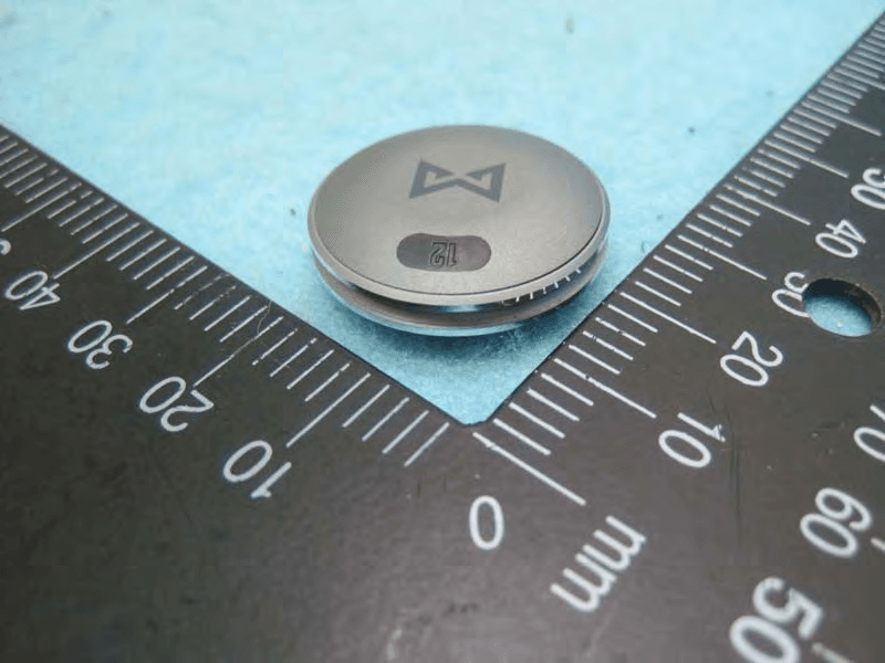
PT3-SH0AZB
May 17, 2015Pedometer
Equipment Class
DXX - Part 15 Low Power Communication Device Transmitter
PT3-SC
Mar 29, 2015Pedometer
Equipment Class
DXT - Part 15 Low Power Transceiver, Rx Verified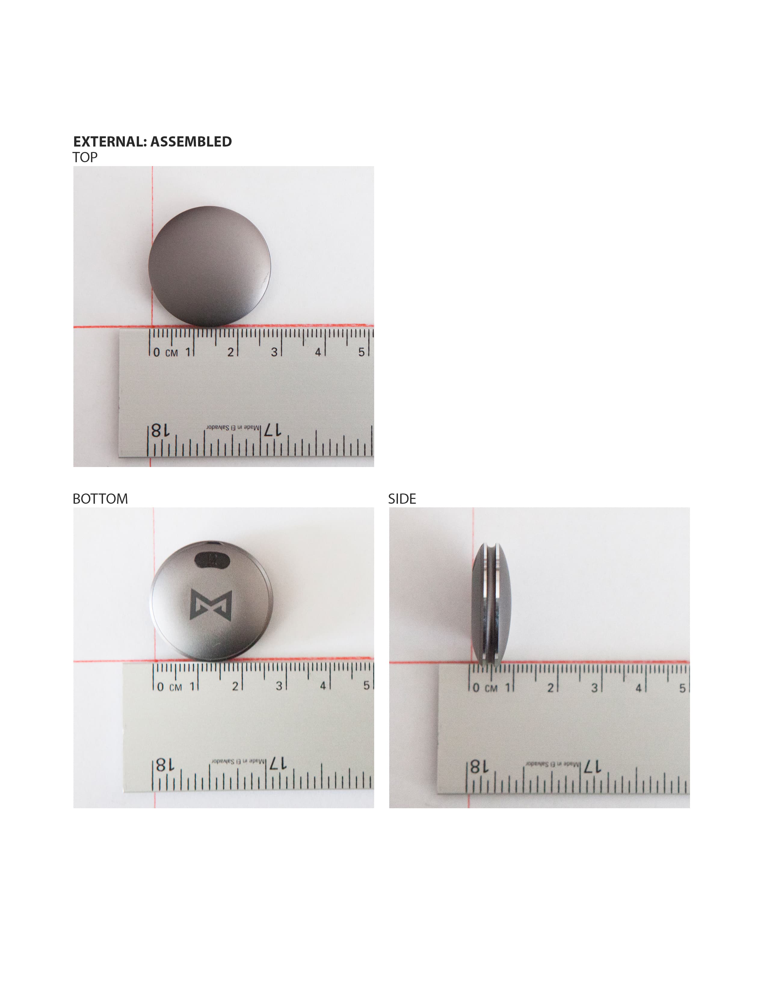
PT3-SH0AZ
Jul 16, 2013Bluetooth Low Energy 4.0 transceiver
Equipment Class
DXT - Part 15 Low Power Transceiver, Rx Verified