PU7E8528P-BMicrowave Oven
shunde Md Microwave Oven Manufactory Co., ltd.
Click to zoom
Application Details
- Equipment Class
- 8CC - Part 18 Consumer Device
- Date of Grant
- Nov 12, 2001
- Application Purpose
- Original Equipment
- Date of Application
- Nov 12, 2001
- Equipment Note
- Microwave Oven
- Frequency Range
- 2450.00000000 - 2450.00000000
- Country
- China
Documents & Files
Document Text
Text extracted from the exhibit documents filed with the FCC. Open a document above to read the original.
Users Manual
INSTRU~TIONS SAFETY MPORTANT service facilily for examina~on, repair or replacement. Do not attempt to service or repc.ir this appliance. 10. Do not cover or block any openings on the appliance. Do not store items on top of microwave oven ii there are louvers on top of oven. 11. Do not store this appiiance outdoors. Do not usa this product near water-for example, near a kitchen sink, in G wet basement, or near a swimming pool, and the like. i 2. Do not immerse cord or plug in water. i 3. Keep cord away from heated surfaces.. 14. 00 not Jet cord hang over edge of table or counter. 15. When cleanina surlaces of door and oven that come togethe; on dosing the door, use only miid, nonabrasive soaps or detergents applied with a sponge or soft cloth. 16. To reduce the risk oj fire in the oven cavity: a. Do not overcook food. espe~ially starc.~y items such as potatoes and fatty items such as bacon. Carefully attend appliance ii paper, plastic, or other combustible materials are .placed inside the oven to facilitate cooking. b. Remove wire twist.Ues from paper or plastic bag before placing bag in oven. c. If materials inside the oven should ignite, keep oven door closed, turn oven oft, and disconnecl the power cord, or shut off power at the fuse or cirC'uit breaker panel. d. Do not use the cavity for storage purposes. Do nolleave paper products: cooking ulensils, or food in Ihe cavily when not in use. e. 00 nol put metal inside the oven, except as spe~ifica"y descnbed In the manual or cookbook if supplied \vith this oven. When using electrical appliances. basic safety precautions should be follo"/ed. incluo1ng the following: VvARNING- To reduce the risk of bums. electrical shock. firs. injury iO persons or exposure to excessive mic:-ow2ve energy: ,. READ ALL. THE INSTRUCTIONS SEFORE USING THE APPLIANCE:. 2. Read and iollow the specific "?rero...autions to avoid possible exposure to excessive mic.-owave energy" found above. 3. Tnis appliance must be grounded and properly polarized. Connect only to a propeliy grounded and p::>iarize-:i ouUsl Sse -G(ouncing Ins\rlJC:jons- on page 3. 4. Install or locate this appiiance only in ac:ordance v/ith the installation instructions described in this manual. 5. Some products such as ,,/hole eggs and sealed containers, such as closed glass jars. may explode and shouid not be heated in this oven. 6. Vse this appliance only for its intended use as described in the manual. 00 not use corrosive chemicals or vapors in this appliance. This type of oven is specifically designed to heat, C:IOk, dry, or defrost food. It is not desioned for industrial, laboratory, or commercial-use. It is intended for home use only. Do not use for drying ctothes,linens. newspaper. or similar non-load type items. 7. Make sure thaI all persons using this appliance, ' especially chiidren, are closely supervised and properly instructed on how to use this appliance. I 8. Do not operate this appliance ij it h2S a damaged c:>rd or plug. ii i: is nOI working propeny, or if it has been oamagcd Or oropped. 9. This appliance should be serviced onl)' by qualified zervic~ per:oonne!. Conlac; the nearest authoriz,erJ A. Do not attempllo operate this oven with C. Do not operate the oven if it is damaged. the door open since open-door operation It is par1icularly impor1an~that the oven door can result in harmful exposure to microwave close properly and that there is no damage to energy. It is important nol to deieat or the (1) Door (bent), (2) hinges and latches tamper "vilh lhe safely interlocks. (broken or loosened), (3) door scals and i . sealing surfaces. i 8. Do nol place any obJecl belween oven front face and the door or allow D. The oven should not be adjusted or repaired soil or cleaner residue to accumulate on by anyone except properly qualified serVice sealing suriaces. personnel. TABLE OF CONTENTS Introduction and Safety precautions 00 1 2 3 4 5 1 2 3 4 5 I ntrod uction Safety Precautions Exploded Views Schematic Diag rams Parts List 1.0 Heating Principle of Microwave 6 Trou bleshooting Proced ures 2.0 7 Common breakdown and means of repairing 3.0 12 Critical Parts Servicing 13 important things to do prior to critical parts servicing interlock assembly replacement and adjustment door and hinge replacement and adjustment magnetron replace ment 13 13 13 13 1 2 3 4 14 Safety checks and tests after servicing 5.0 1 2 3 14 14 15 constructional checks insulation resistance test microwave leakage test This Microwave Oven Service Manual is printed in a loose leaf format. Each part is divided into sections relating to a general group of components and each section is subdivided into various parts describing a particular component or service procedure. The subdividing of the subject matter plus the loose leaffonn Will facilitate Ute updating of the manual as new or revised components and service procedures are introduced. Each page of this service manual will be identified in the lower right hand comer and as new or revised pages are published it will be easy to keep the manual up to date by following the filing instructions on the cover letter. This Service Manual is a valuable service tool and .care should be taken to keep it up to date by prompt and proper filling of subsequent pages as they are issued. SAFETY PRECAUTIONS !PRECAUTIO,NS TO BE OBSERVED BEFORE AND DURING SERVICING TO AVOID IPOSSIBLE EXPOSURE TO EXCESSIVE MICROWAVE ENERGY: IA. Do not operate or allow the oven to be operated with the door open. B. Make the following safety checks on all ovens to be serviced before activating the magnetron or other microwave source, and make repairs as necessary. ( 1 ) Interlock operation ( 2.) Proper door closing (3) Seal and sealing surfaces (arcing, wear, and other damage ). 4) Damage to or loosening of hinges and latches. ( 5) Evidence of dropping or abuse. C. Before turning on microwave power for any service test or inspection within the microwave generating compartments, check the magnetron, wave gui…
Text truncated - open the document above for the full version.
Users Manual
TROUBLESHOOTING PROCEDURES DCI - f .. o bawiqa aIkrowaft "ea. JGU lbouI4 Judp the ~dowa 8ad tbe ca.-e mrrcctl,. tbea,.. CAD nP8ir h with rClpoadl-. wa," TIae ".haW", mUiC be praceed ID _4.. an, ba8t, coaclUlIon .. Dot r~~'le. _bcrwlle VNf. "kJDI would be dCMIe wbcn rep8lr. Thc _Icrowa.e 0... ala' ~ur ca1pouad breakdown 4- to aU kIDdI vi different IOAI. thai. wbeD OYcrbaui. tlte, aU .bouad be takc Into ConIld..CJoa. lipeci.1 aUcatIoa mult .. 1l.8ft to the -Icrowa.e UII aad the elKtrlc wulatlCMa WbCD ualDlDc becau.e the, may do barlr.ful to the rcpalrll1l .tall. MEANS OP THE BREAKDOWN EXAMINING. " How to uamlne a _lcrowaYe OYCD wltb brcakdoWD1 A better mcanl wbl~ dcmoaltrated In practlu) opcratlq ... tb.-.JI Inspect... and U.tenlnl. OD the baa.. oflarae amountl 01 perceptual knowled.e. you can Judp and .DaI,,11 the --. down quickly and cwrcctl. . .. laspectJoa. lllapcd whether the OVct1 shape II dl..dcred and wbeR Is the dllor4ered position. Ilany. 18 II 1a'm81 11 the C8blnel disordered 8 little. btlt abnormal II the oyen. the dC»r disordered. the dOCN' hook broken. the door cnxIked. w then are 100 much looscnal between the dCXJr 8nd the oyen after the door II closed. 1. Ustenlnl. Usi-lns to the voice 01 the o.en operatfna and the nolle or the Ian after It ~ucted. MIIIOf -wco wen" nolle. c7cllnl nolle and -,hllhl" Mise should be consider al normal. But it II abnorm8111 the rollowlna nolle occured: (.) Sound -wen wen- nol,e. (Z) Lmll time "shlshl" IIGlse. , (3) Strike voice Uke "plpa ptpa". SPOT EXAMINING STEPS Of THB MICROWAVE OVEN. I. ExamIne Ih. mlcrowa.. Insulatlna realstaKe. Meaa"'8 the InsulaClnl resistance wIth. aYOlIICCer or . &nepoJlmalcler Cbe ..Iue should IKJt less Cban 2 mcpoh81. Oth- erwtse. part eamlutlon I_ad be taken .t once. Sucb as checklnl whether Cbe motor. the thcrm81 cutout. the trans- IOrmer or the C8pacltor .re electricity leeklnl. 1. Eum~tJoa of the rcslltaKe value or the mlcrowaye oven. i Close rIle door. act the tJlDC.(thc OVcD II at Of)er.tlnl condition but the power pluS havn't been pluaed In). _casure I the two rett (L- N) 01 tbe power pluS with R Xl Ifade ola ayometer. the r..altance value lhould be abOllt 1.5 ohm. , 11 open drcult ~ured. tllcn you must check wllcCher the 8A ruse II broken. the prlmar7 wlndlq 01 the traasrormcr Is open drculC. tIle thermal cutout I. open circuit or not. you mult check whether the Interlock dcylce II put tbroup or an the plull .r. connected wcll. Ir short drculC OCCUl'ed or Chc rdlistance less than 1.5 ohm. you should cllcck whether tbe prima" willdina or tllC power transrCN'mer I. sbort - circuited or part .hort - circuited. ! 3. Bumln.tlon of _Icrowave leakaac. Measure the mlcrowa.. leakale with a mlcrowa.e leaD Ie measure. Place a paduate or 275mJ water at the middle or the alas. tray or the o.en (fiG. 5 - 1). CI~e tllC door. power act hIgh. time let to 3 minutes. pre.. the startl. button to operate the oycn. After redtlOed the microwave leauge measure. measure arOllnd the door crack. thOle hole posl- tlOll or tbe window and the air yent .t roul' aides or the oven with the probe or thc measure. When -easul'c. the mavIns lpeed or til. probe Ihould not CKcecd 25-m pcr second. and the mcl'surlng directlOll should be Chc s.ate with the outina dlrecaloo or tile micro tcakale (fiG. 5 - 2). \\'baa measurial. the ultimate value or microw.ve ic.".ge or all the measured position should not exceed 1 mllllwa"1 cmJ. or Ihould be considered as abnormal. 4. &amine when the OVeD at operating. but the lood an' t be heated. (I) Enmlne when the lamp .. 01'. thc llall tray II cycllnl. the ran operating In norm8l: I Take olr the C8bJnet. ItanlD1 the UYen. mea.ure Ih. pluS or the Iransrormcr with a ayometcr to Ice whether It lie. nou&II to .20v. Ir It is enou,h to 120v. Ihcn the sccond.ry hlah .oltage or the transrormer should be a.mined as FIG.! - 3. Measure It with the 1SOUV alt~rnatlnB Ifade of model 500 avomctcr. One rod 01 the avometer connect the ir81 core of the transformer. the other rod connect the secondary hlBh voltaic plug (FIG. S - .). The avometer readinB shoul~ be about 1100V (when measure. be careful with the high yoltale). If no yoltale at all. It IlIdlcatcs that the trap.former has broken. and should be replaced by a new one. If it I. enoulh to 1100V. then check the filament voitaBc of thc transformer with alternatlnl 10 V Irade of a avometer. the value should be about 3.. V (FIG. S - S) . ~~ Tf8UI- SecondIry - '~I I j Pri-r _IDd-. Pil.S - 3 Fil.5-4 ~ g Fig. 5 - 5 Fig.5 - 6 . Fig. 5 - 7 If there is no Yoitage at all, it indicates the tranJ!ormer has broken, and should be replaced by a new one. If it i. enough to 3.4 V, check the filament resistance or the magnetron, measure the filament plug with the R x 1 grade or a avometcr (FIG. 5 - 6). If It is open - cirC1!itcd, It indicates the magnetron has broken, and should be replaced by a new one. It is normal If the resistance vaiue Is very small. Then check whether the magnetron steel has brocken, If broken, replace with a new magnetron. If there Is no problem with the magnetron, check tile blah voltaic diode then. Measure the diode with R x 10K grade or a avometer, the" + .. rod end of the avometer connect the cathode of the diode, the" - " rod end of the avometer connect the anode of the diode (FIG. 5 - 7). The avometer readlnlsbould be a~t 150 thousand ohm. Then change the rod to different electrode, the reading should be .. = ". If the reading Is yery small, and near to short circuit, It indicates tile bigh voltage diode bas been punctured, and should be replaced by a new one. SecaIId-.7-WIaa FiB-S - 8 FIa'S -, ~~~ If the high voltage di(xle Is OK. . then check the forwardJng pluS of the tran.former to lee whether It il ~ah to IZOv. if It isl1ot en(Mlgh. check 'the micro-switch of the time and (XIwer distributer. Connect the two rod of the avumeter to the 1.2 place of the timer with R)( a K grade.lt Is normal If the reading I, "O"whcn at cut off condi. tion.' If the reading is "…
Text truncated - open the document above for the full version.
External Photos
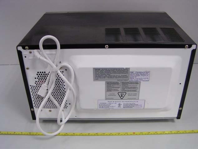
EUT – Chassis Front View EUT – Chassis Rear View EUT – Chassis Top View EUT – Chassis Bottom View
ID Label/Location Info
FCC PRODUCT LABELING AND WARNING STATEMENT Proposed FCC Label Format Specifications: Text is white in color and is left justified. Labels are silk-screened and shall be “permanently affixed” at a conspicuous location on the EUT. Proposed Label Location on EUT Rear View of EUT Proposed FCC ID Location FCC Warning Statement Generally the FCC Warning Statement is provided in the product manual. Per FCC Section 15.19 (3), all devices shall bear the following statement in a conspicuous location on the device: “This device complies with Part 15 of the FCC Rules. Operation is subject to the flowing two conditions: (1) this device may not cause harmful interference, (2) this device must accept any interference received, including interference that may cause undesired operation.” When the device is so small or for such use that it is not practicable to place the statement specified, the information shall be placed in a prominent location in the instruction manual or pamphlet supplied to the user or alternatively, shall be placed on the container in which the device is marketed. However, the FCC identifier or the unique identifier, as appropriate, must be displayed on the device. FCC:PU7E8528P-B
Internal Photos
EUT – Chassis Uncovered Left View EUT – Chassis Uncovered Right View EUT – Chassis Uncovered Top View Controller PCB Component View Controller PCB Solder View
Test Report
Note: This report may not be duplicated without prior written consent of Bay Area Compliance Laboratory Corporation. This report must not be used by the client to claim product endorsement by NVLAP or any agency of the U.S. Government. FCC ID PER PART 18 EMI MEASUREMENT AND TEST REPORT For Shunde MD Microwave Oven Manufactory Co., Ltd. Penglai Road, Beijiao, Shunde, Guangdong, P.R. China FCC ID: PU7E8528P-B November 12, 2001 This Report Concerns: Original Report Equipment Type: Microwave Oven – Consumer ISM Equipment Test Engineer: Hien Pham Test Date: October 29, 2001 Reviewed By: John Y. Chan – Engineering Manager Prepared By: Bay Area Compliance Laboratory Corporation 230 Commercial Street, Suite 2 Sunnyvale, CA 94085 Tel: (408) 732-9162 Fax: (408) 732-9164 Shunde MD Microwave Oven Manufactory Co., Ltd. FCC ID: PU7E8528P-B Report # Test report FCC ID Per Part 18 Test Report Page 2 of 16 TABLE OF CONTENTS 1 - GENERAL INFORMATION.................................................................................................................................................3 1.1 PRODUCT DESCRIPTION FOR EQUIPMENT UNDER TEST (EUT)........................................................................................3 1.2 OBJECTIVE................................................................................................................................................................................3 1.3 TEST METHODOLOGY..............................................................................................................................................................3 1.4 TEST FACILITY.........................................................................................................................................................................3 1.5 TEST EQUIPMENT LIST AND DETAILS...................................................................................................................................4 1.6 LOCAL SUPPORT EQUIPMENT LIST AND DETAILS...............................................................................................................4 2 – OPERATING CONDITION/TEST CONFIGURATION.............................................................................................5 2.1 JUSTIFICATION..........................................................................................................................................................................5 2.2 SCHEMATICS / BLOCK DIAGRAM...........................................................................................................................................5 2.3 EQUIPMENT MODIFICATIONS.................................................................................................................................................5 2.4 CONFIGURATION OF TEST SYSTEM.......................................................................................................................................6 2.5 TEST SETUP BLOCK DIAGRAM...............................................................................................................................................6 3 – RADIATION HAZARD MEASUREMENT.....................................................................................................................7 3.1 RADIATION HAZARD MEASUREMENT...................................................................................................................................7 3.2 INPUT POWER...........................................................................................................................................................................7 3.3 LOAD FOR MICROWAVE OVENS............................................................................................................................................7 3.4 RF OUTPUT POWER MEASUREMENT....................................................................................................................................8 3.5 OPERATING FREQUENCY MEASUREMENT............................................................................................................................9 4 - RADIATED EMISSION DATA..........................................................................................................................................15 4.1 MEASUREMENT UNCERTAINTY...........................................................................................................................................15 4.2 EUT SETUP.............................................................................................................................................................................15 4.3 SPECTRUM ANALYZER SETUP..............................................................................................................................................15 4.4 TEST PROCEDURE..................................................................................................................................................................15 4.5 CORRECTED AMPLITUDE & MARGIN CALCULATION.......................................................................................................16 4.6 SUMMARY OF TEST RESULTS...............................................................................................................................................16 4.7 RADIATED EMISSIONS TEST RESULT DATA.......................................................................................................................16 Shunde MD Microwave Oven Manufactory Co., Ltd. FCC ID: PU7E8528P-B Report # Test report FCC ID Per Part 18 Test Report Page 3 of 16 1 - GENERAL INFORMATION 1.1 Product Description for Equipment Under Test (EUT) The Shunde MD Microwave Oven Manufactory Co., Ltd.’s model, E8528P-B or the “EUT” as referred to in this report is a microwave oven which measures approximately 15.00”L x 20.25”W x 11.25”H. The EUT provides following features: • Micro Wave Main Unit Manufacturer: SAMSUNG Model: OM75S(31) Seri…
Text truncated - open the document above for the full version.
Test Setup Photos
Setup Photographs Conducted Setup Photograph – Front View Conducted Setup Photograph – Side View Variation with Time Setup – Front View Variation with Time Setup – Rear View Variation with Voltage Setup – Front View Variation with Voltage Setup – Rear View
Contact Information
Applicant
Xiaodong Wu(Engineer)
Test Firm
Bay Area Compliance LaboratoryJohn Chan
Technical Specifications
| # | Rule Parts | Frequency Range | Power Output |
|---|---|---|---|
| 1 | 18 | 2.45 GHz - 2.45 GHz | - |
Other Applications from shunde Md Microwave Oven Manufactory Co., ltd.
PU7CN8525
Jul 28, 2003Microwave Oven
Equipment Class
8CC - Part 18 Consumer Device
PU7EV1044X-Y
Jan 16, 2003Microwave Oven
Equipment Class
8CC - Part 18 Consumer Device
PU7M5012X-Y
Jan 16, 2003Microwave Oven
Equipment Class
8CC - Part 18 Consumer Device
PU7E1028X-Y
Aug 06, 2002Microwave Oven
Equipment Class
8CC - Part 18 Consumer Device
PU7E1037X-Y
Aug 06, 2002Microwave Oven
Equipment Class
8CC - Part 18 Consumer Device