PUCYCT-107WIRELESS TRANSMITTER
Tracking Technology Corp.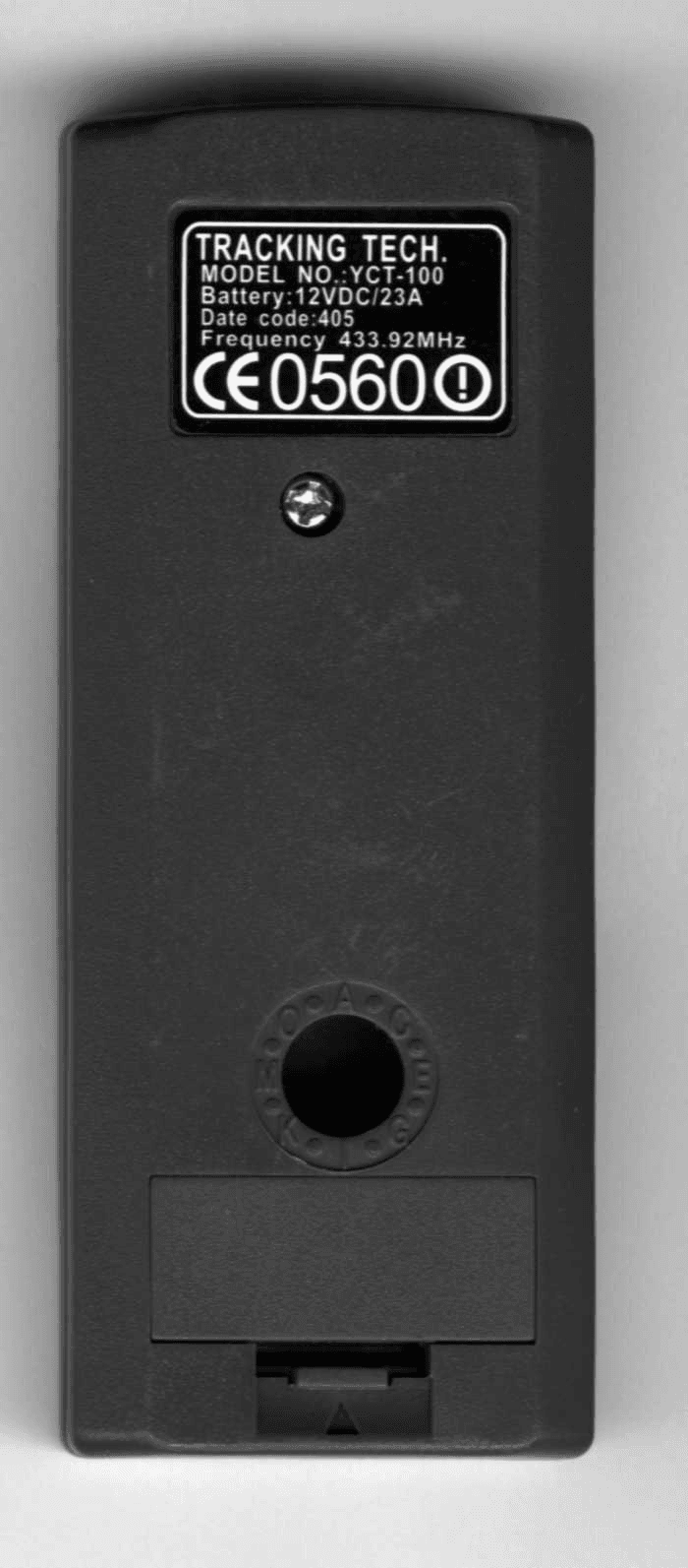
Click to zoom
Application Details
- Equipment Class
- DSC - Part 15 Security/Remote Control Transmitter
- Date of Grant
- Mar 06, 2005
- Application Purpose
- Original Equipment
- Date of Application
- Mar 06, 2005
- Equipment Note
- WIRELESS TRANSMITTER
- Frequency Range
- 434.00000000 - 434.00000000
- Company
- Tracking Technology Corp.
- Country
- Canada
Documents & Files
Document Text
Text extracted from the exhibit documents filed with the FCC. Open a document above to read the original.
Users Manual
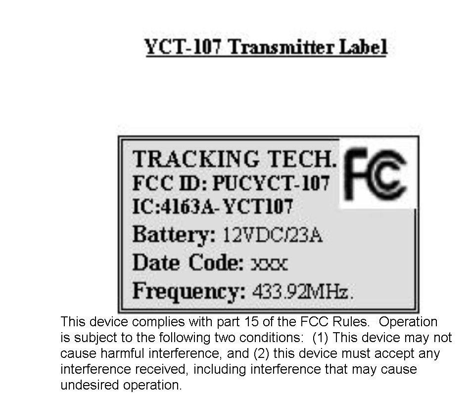
USER MANUAL Model YCT-100 (YCT-107) FEATURES: • Works with CMR-1000, TKR-302 • Code switch allows changing to another address to avoid neighbouring interferences • Simple push button operation CODE SWITCHES: • House Code: Allows change to another channel than your neighbour’s • Unit Code: Receiver individual code OPERATION: • On/off function (YCT-100) • Dimmer function (single channel YCT-107, multi channel YCT-100) • Heater function (YCT-107) • Heat Hi/Lo function (YCT-107) SPECIFICATIONS: • Radio Frequency: 433.92MHz. • Power: <26uW • Battery: 12V (type 23A) Radio Frequency: FCC and IC This device complies with part 15 of the FCC Rules. Operation is subject to the following conditions: this device may not cause harmful interference, and this device must accept any interference received including interference that may cause undesired operation. The manufacturer is not responsible for any radio or TV interference caused by unauthorized modification to this equipment. Such modifications could void the user’s authority to operate the equipment.
Block Diagram
LED 12v battery EncoderIC101 TransmitterQ101 433.92MHzSAW Osc. Tact Switches YCT100 Transmitter
Operational Description
Current Flame Fireplace Multifunction Operation Description Introduction: The Current Flame Electric fireplace consists of a steel box enclosure. Inside the enclosure, there are four incandescent lamps. Two mount horizontally in the lower centre section in front of the flag blower. The other two stand vertical at either side of the box. A small, low volume cross flow blower, mounted on the lower part of the back wall, provides the airflow to move the flame-like fabric strips or “flags”. In a separate compartment across the top of the enclosure is a heater unit. It consists of two metal heating elements and a second cross flow blower. The AC power cord enters the top of the box and travels down the inside left back and across to the bottom front left panel. Here it connects to a main power switch. The switch provides power to a radio frequency remote control receiver, located on the floor of the enclosure to the left side. The receiver controls all component functions. Electrical Operation: An eight foot, three-conductor power cord supplies house current to the Current Flame electric fireplace. In the inside, lower left corner is an illuminated main power switch that turns the input power on and off. The switch provides all AC power to the fireplace. The line out of the switch wires directly to the remote receiver board input terminals. All electrical components wire directly to the outputs of the receiver board. Receiver Board: The receiver PCB mounts on four nylon stands that hold it in place, 0.375 inches above the steel floor of the fireplace enclosure. A terminal strip with screw-down connections mounted on the rear edge of the receiver board provides input and output for all AC Line and Neutral connections. An on-board transformerless power supply provides the low voltage of +24vdc to operate the receiver. The 78L05-voltage regulator produces the required 5vdc to operate the RF and the controller circuitry. The lamp dimmer circuit consists of an LRC circuit, a BAT08 TRIAC and a 2712 gate control transistor. This transistor changes the turn-on time of the TRIAC, changing the power out thereby changing the intensity of the lamps. The MDT10P61 microcontroller uses a zero crossover detector, 2712 transistor to sample the AC phase and synchronise its dimmer control output pulses. The control pulses trigger the gate control transistor. Software in the microcontroller adjusts the delay of the pulses from the zero crossover reference. The microcontroller uses received commands that tell it to advance and retard the delay in a continuous loop or hold the delay time setting. The microcontroller takes commands for operation of the blowers and heaters and translates them into high and low DC voltage outputs to trigger the 2712 driver transistors that supply the 24vcd to the Line relays. There are three relays. Relay RLY201 switches the flag blower on and off. Relay RLY202 switches the heater blower and first heater element on and off. Relay RLY203 switches the second heater element on and off. The RF receiver circuit is of the super-regenerative type. It operates at 433.92MHz with an ASK modulation. The antenna is an etched end-fed track on the board. The LM358 dual OP amp amplifies and conditions the received signal pulses and sends the series set of data pulses to the microcontroller. There is a 4-line Dipswitch on the board to allow manual setting of the receiver address codes. Transmitter: The RF transmitter has a two-transistor output driver that uses a SAW device to control the carrier frequency at 433.92MHz. It uses ASK modulation. The antenna is an etched folded dipole on the transmitter PCB. Pressing of one of the momentary, tactile command switches predetermines data selection. The switches connect to the I/O pins of the M3E-A microcontroller. The microcontroller sends the data to the RF drivers. A manually operated rotary dial, located on the rear of the transmitter sets the address codes. A 12-volt internal battery supplies power to the transmitter. A red LED indicator located in the front, top left corner illuminates whenever a button is pressed and flickers during transmission time. Transmissions are less than 5 seconds duration.
Contact Information
Applicant
Thomas Murawsky(President)
Test Firm
Timco Engineering, Inc.S Sanders
Technical Specifications
| # | Rule Parts | Frequency Range | Power Output |
|---|---|---|---|
| 1 | 15.231 | 434 MHz - 434 MHz | - |
Other Applications from Tracking Technology Corp.

PUC-ERX10
Apr 01, 2003Remote Control Transmitter
Equipment Class
DXX - Part 15 Low Power Communication Device Transmitter
PUCTTC2001SH
Sep 17, 2001Security/ Remote Control Transmitter
Equipment Class
DSC - Part 15 Security/Remote Control Transmitter