PV5MSD033319911:24 scale R/C Nascar car-Remote Toy Controller
Meisida Electronic Toys Co., Ltd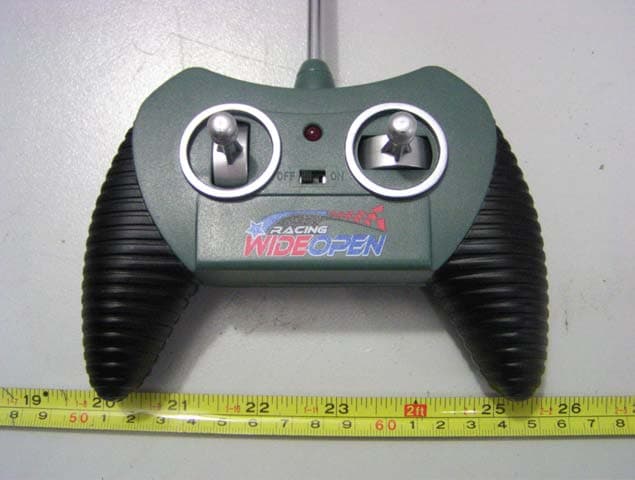
Click to zoom
Application Details
- Equipment Class
- DXX - Part 15 Low Power Communication Device Transmitter
- Date of Grant
- Nov 23, 2003
- Application Purpose
- Original Equipment
- Date of Application
- Nov 23, 2003
- Equipment Note
- 1:24 scale R/C Nascar car-Remote Toy Controller
- Frequency Range
- 40.66000000 - 40.70000000
- Country
- China
Documents & Files
Document Text
Text extracted from the exhibit documents filed with the FCC. Open a document above to read the original.
Users Manual
Forward and backward operation Left and right turn operation Steering alignment lever PROBLEM Car does not move or runs slowly Car moves erratically or transmitter range is short Car does not work after going through water or snow PROBABLE SOLUTIONS •Make sure power switch on vehicle and transmitter are in the ON position •Make sure the batteries in the vehicle and transmitter are installed properly •Recharge vehicle's NiCd battery pack or replace if necessary •Replace 9V battery in transmitter with fresh alkaline battery •There is radio interference in the area- change locations •There is another R/C vehicle operating on the same frequency near by- move away from any other vehicle operating on the same frequency •Make sure antenna in transmitter is screwed in tight and fully extended •Make sure transmitter battery connections are in good condition and replace battery •Allow car to dry thoroughly overnight •Avoid driving in water or snow Place car on smooth, flat surface and extend antenna fully. To move car forward and backward in a straight line, move the left lever up and down. To turn left or right while moving forward, move the right lever side to side while holding the left lever up. To turn left or right while moving backward, move the right lever side to side while holding the left lever down. NOTE: For maximum performance, hold the transmitter upright so the antenna points up (do not point the antenna at the car- this will reduce the signal range). Adjust the steering alignment lever located on the bottom of the car if the car does not run straight when moving forward (refer to drawing on opposite page for location of steering alignment lever). 1. 2. 3. 4. 5. 1. 2. 3. 4. 5. Remove the battery cover on the bottom of the transmitter and connect the 9V battery to the wire plug. Insert battery into compartment and replace the battery cover. Insert the antenna into the top of the transmitter and screw in tightly. Move the power switch on the transmitter to the ON position. Remove the battery cover on the bottom of the car. Install the battery pack by connecting the wire plug from the car to the wire plug on the battery pack. Insert the battery pack into the bottom of the car and replace the battery cover. Move the power switch on the bottom of the car to the ON position
Users Manual
BATTERY REQUIREMENTS: Vehicle: 1 x 4.8V NiCd rechargeable battery pack Controller: 1 x 9V alkaline battery (included in this package) OWNER'S MANUAL Please read carefully before operating your vehicle. Keep these instructions for future reference as they contain important information Manufactured under license by: TEAM UP INTERNATIONAL, INC. 4545 Enka Highway Morristown, TN 37813 423-585-5300 Made and printed in China Connect the wire plug of the battery pack to the wire plug of the charger. Plug the charger into a standard 110/120V electrical outlet. Charge for approximately 8 hours for the first charge. Subsequent recharges require only 4-6 hours. Unplug the charger from the outlet and detach the wire plug connectors. NOTE: Do not pull on wires, as they may come loose from the plug connectors. 1. 2. 3. 4. IMPORTANT: Battery pack is not charged when newly purchased- charge before using. ATTENTION PARENTS: It is recommended that this toy and all accessories be periodically examined for potential hazards and that any potentially hazardous parts be repaired or replaced. THIS PRODUCT USES A NICKEL-CADMIUM RECHARGEABLE BATTERY PACK- BATTERY MUST BE RECYCLED OR DISPOSED OF PROPERLY. • Batteries should be inserted with the correct polarity. • Do not short circuit battery contacts. • Do not mix old and new batteries. • Do not mix alkaline, standard (carbon-zinc) or rechargeable (nickel-cadmium) batteries. • Remove batteries if vehicle will not be used for a long period. • Check the batteries regularly for leakage. • Exhausted batteries should be removed from the charger. • Do not dispose batteries in a fire - batteries may leak or explode. • Use only the recommended batteries or batteries of equal quality/type. • Do not recharge non-rechargeable batteries. • Remove battery pack from vehicle before recharging. • Do not pull on wires when detaching the battery pack plug/connector. • Do not recharge warm or hot battery packs- wait until pack has cooled. • Do not overcharge - this may damage the battery pack. • Recharging too early will shorten battery pack life. • Do not recharge batteries that show wear or leakage. • Do not recharge in high temperatures or bring the battery pack near a flame. • Do not let the charger or battery pack get wet or damp. • Do not take the charger or batter pack apart. • Rechargeable batteries should always be charged under adult supervision. BATTERY PERFORMANCE NOTE: For best performance use alkaline batteries (where disposable batteries are called for). If your vehicle is supplied with standard (carbon-zinc) batteries for initial use and/or demonstration purposes, we recommend replacing them with alkaline batteries when necessary. Battery life may vary depending on battery brand. •Do not operate during thunderstorms. •Avoid water, sand, and snow when operating your vehicle. In addition, do not submerge your vehicle or controller in water. •Never operate your vehicle on the street or highway. •Never operate your vehicle in a confined or crowded area, and do not use people or animals as obstacles. •Do not run your vehicle into furniture, objects or hard surfaces, as this will cause damage to both the objects and the vehicle. •Keep fingers, hair, and loose clothing away from the tires, gears, and motor while the vehicle is switched ON. •Do not leave vehicle or controller near sources of heat or under direct sunlight for long periods of time. •Do not leave vehicle or controller outside overnight- dampness is harmful to interior components. •Remove all batteries when not in use to avoid accidental operation. Adult supervision is recommended when operating this vehicle. This equipment has been tested and found to comply with the limits for a Class B digital device, pursuant to Part 15 of the FCC Rules. These limits are designed to provide reasonable protection against harmful interference in a residential installation. This equipment generates, uses and can radiate radio frequency energy and, if not installed and used in accordance with the instructions, may cause harmful interference to radio communications. However, there is no guarantee that interference will not occur in a particular installation. If this equipment does cause harmful interference to radio or television reception, which can be determined by turning the equipment off and on, the user is encouraged to try to correct the interference by one or more of the following measures: •Reorient or relocate the receiving antenna •Increase the separation between the equipment and receiver •Connect the equipment into an outlet on a circuit different from that to which the receiver is connected •Consult the dealer or an experienced radio/TV technician for help This device complies with part 15 of the FCC Rules. Operation is subject to the following two conditions: 1. This device may not cause harmful interference, and 2. This device must accept any interference received, including interference that may cause undesired operation of the device. CAUTION: Any changes or modifications not expressly approved by the party responsible for compliance could void the user's authority to operate the equipment. CAUTION- ELECTRIC TOY: Not recommended for children under 8 years of age. As with all electrical products, precautions should be observed during handling and use to reduce the risk of electric shock. FCC NOTES SAFETY BATTERY PRECAUTIONS 1:24 SCALE RADIO CONTROL
Block Diagram
~ Direction control Amplifier Code Modulation Oscillator 40 MHZ
External Photos
External Photos EUT - Front View (1) EUT- Back View (1) EUT - Front View (2) EUT- Back View (2)
ID Label/Location Info
ID Label Label FCC ID: PV5MSD03331991
ID Label/Location Info
ID Label/Location Label Location Information Specifications: Text is Black or white in color and is left justified. Labels are printed in indelible ink on permanent adhesive backing or silk-screened onto the EUT or shall be affixed at a conspicuous location on the EUT. Refer to the below arrow.
Internal Photos
Internal Photos EUT –PCB View (1) EUT –PCB View (2) EUT –PCB View (3)
Operational Description
Circuit Description of 0333 Receiver and Transmitter The signal flowing of Transmitter: At usual time, the IC coding signal are sent to R5 and the carrier frequency vibrating signal are sent to L6 for coupling respectively, then the signal is sent to Q1 for modulating & magnifying, C3 for coupling and L1 for inducting. And then sent to transmitting antenna finally. The signal flowing of Receiver: When the signal is received by the antenna, it will coupling via C1 followed by L2,C3 for frequency choice. the receiver oscillating and regenerated signal is coupled by R3,C7. then input to inverter via IC pin14, output via IC pin15 followed by IC pin16, the 2nd inverter input pin. The signal is output via IC pin1 and sent though R3 to IC pin3 for demodulating, and output though functions pins finally. IC pin10 output ‘forward’ (high voltage) signal, then Q3 output positive voltage and Q5 output negative voltage via R13 and Q6 conduct, then the motor is working and vehicle go forward. IC pin11 output ‘backward’ signal and pin6 and pin7 output ‘turn left ’ and ‘turn right’ signal respectively. The working mode of these signals is like ‘forward’ signal.
Test Report
Note: This test report is specially limited to the above client company and the product model only. It may not be duplicated without prior written consent of Bay Area Compliance Laboratory Corporation. This report must not be used by the client to claim product endorsement by NVLAP or any agency of the U.S. Government. FCC PART 15 Subpart C EMI MEASUREMENT AND TEST REPORT For Meisida Electronic Toys Co., Ltd. Anping Indsutry Park (Anhai) Jinjiang Fujian China FCC ID: PV5MSD03331991 November 5, 2003 This Report Concerns: Original Report Equipment Type: 1:24 scale R/C Nascar car Test Engineer: Chris Report No.: RSZ03091103 Test Date: October 31, 2003 Reviewed By: Prepared By: Bay Area Compliance Lab Corp. Suite C, 41-D Electronics Science & Technology Building, No. 2070 Shennanzhong Rd ShenZhen, Guandong 518031, P.R. China Tel: (755) 83296449 Fax: (755) 83273756 Meisida Electronic Toys Co., Ltd. FCC ID: PV5MSD03331991 Report # RSZ03091103 Page 2 of 14 FCC Part 15 Subpart C Test Report TABLE OF CONTENTS 1 - GENERAL INFORMATION..................................................................................................................................3 1.1 PRODUCT DESCRIPTION FOR EQUIPMENT UNDER TEST (EUT) ..............................................................................3 1.2 OBJECTIVE.............................................................................................................................................................3 1.3 RELATED SUBMITTAL(S)/GRANT(S) ......................................................................................................................3 1.4 TEST METHODOLOGY............................................................................................................................................3 1.5 TEST FACILITY.......................................................................................................................................................3 1.6 TEST EQUIPMENT LIST...........................................................................................................................................4 2 - SYSTEM TEST CONFIGURATION.....................................................................................................................5 2.1 DESCRIPTION OF TEST CONFIGURATION................................................................................................................5 2.2 CONFIGURATION OF TEST SYSTEM.........................................................................................................................5 2.3 TEST CONFIGURATION PHOTOS..............................................................................................................................5 2.4 EQUIPMENT MODIFICATIONS.................................................................................................................................6 3 - SUMMARY OF TEST RESULTS..........................................................................................................................7 4 – ANTENNA REQUIREMENT ................................................................................................................................8 5 - CONDUCTED EMISSIONS TEST DATA............................................................................................................9 6 - RADIATED EMISSION DATA ...........................................................................................................................10 6.1 MEASUREMENT UNCERTAINTY............................................................................................................................10 6.2 EUT SETUP..........................................................................................................................................................10 6.3 SPECTRUM ANALYZER SETUP..............................................................................................................................10 6.4 TEST PROCEDURE................................................................................................................................................10 6.5 CORRECTED AMPLITUDE & MARGIN CALCULATION...........................................................................................11 6.6 SUMMARY OF TEST RESULTS...............................................................................................................................11 6.7 RADIATED EMISSIONS TEST RESULT DATA.........................................................................................................11 6.8 TEST RESULT: PASS.............................................................................................................................................11 7 – BAND EDGES TESTING.....................................................................................................................................12 7.1 SPECTRUM ANALYZER SETUP..............................................................................................................................12 7.2 TEST DATA..........................................................................................................................................................12 7.3 TEST RESULT.......................................................................................................................................................12 8 – FREQUENCY STABILITY TESTING...............................................................................................................14 8.1 TEST DATA..........................................................................................................................................................14 8.2 TEST RESULT.......................................................................................................................................................14 Meisida Electronic Toys Co., Ltd. FCC ID: PV5MSD03331991 Report # RSZ03091103 Page 3 of 14 FCC Part 15 Subpart C …
Text truncated - open the document above for the full version.
Test Setup Photos
Test Setup Photos Test Setup Photos Radiated Emission – Front View Radiated Emission – Rear View Frequency Stability Test Photo
Contact Information
Applicant
Heng Yi Lu(General Manager)
Test Firm
Bay Area Compliance Laboratory Corp. (Shenzhen)John Chan
Technical Specifications
| # | Rule Parts | Frequency Range | Power Output |
|---|---|---|---|
| 1 | 15C | 40.66 MHz - 40.7 MHz | - |
Other Applications from Meisida Electronic Toys Co., Ltd
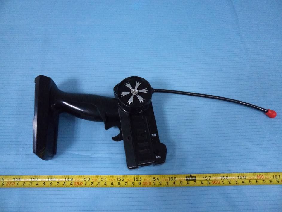
PV5MSD11061989
Dec 21, 2011R/C Car
Equipment Class
DXX - Part 15 Low Power Communication Device Transmitter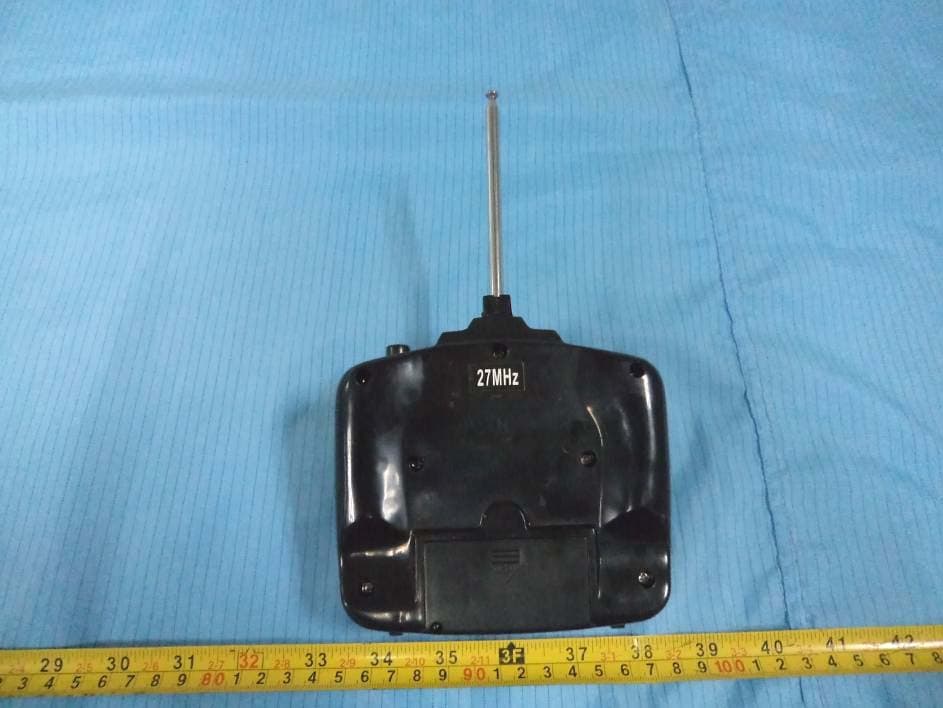
PV5MSD30091989
Nov 19, 2011GIANT WHEELS
Equipment Class
DXX - Part 15 Low Power Communication Device TransmitterPV5MSD09021990
Jul 21, 2010STUNT ROLLING CAR
Equipment Class
DXX - Part 15 Low Power Communication Device Transmitter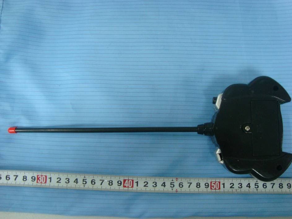
PV5MSD09021989
Jul 21, 2010STUNT ROLLING CAR
Equipment Class
DXX - Part 15 Low Power Communication Device Transmitter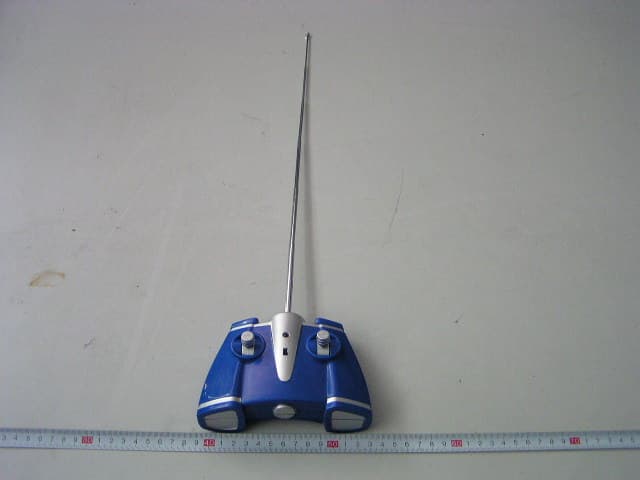
PV5MSD05221989
Feb 06, 2007WATER-BLAST CRUISER
Equipment Class
DXX - Part 15 Low Power Communication Device Transmitter