PW2DTXPRO2300U2.3KW DTV TRANSMITTER
Pineapple Technology, Inc.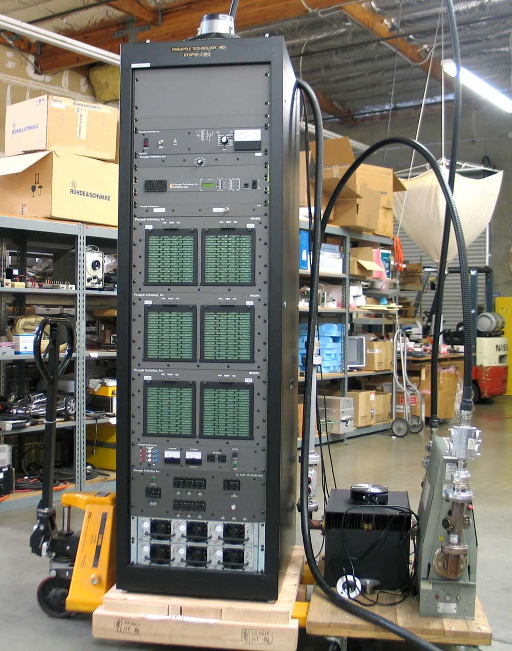
Click to zoom
Application Details
- Equipment Class
- TBC - Licensed Broadcast Station Transmitter
- Date of Grant
- Mar 01, 2011
- Application Purpose
- Original Equipment
- Date of Application
- Feb 07, 2011
- Equipment Note
- 2.3KW DTV TRANSMITTER
- Frequency Range
- 614.00000000 - 806.00000000
- Company
- Pineapple Technology, Inc.
- Country
- United States
Documents & Files
Document Text
Text extracted from the exhibit documents filed with the FCC. Open a document above to read the original.
Users Manual
PINEAPPLE TECHNOLOGY, INC. TABLE OF CONTENTS DTXPRO-2.3KU OPERATING AND SERVICE MANUAL THE INFORMATION PROVIDED HEREIN IS PINEAPPLE TECHNOLOGY INCORPORATED PROPRIETARY INFORMATION AND CANNOT BE COPIED OR DISTRIBUTED WITHOUT PRIOR AUTHORIZATION TABLE OF CONTENTS SECTION I – SAFETY NOTICES....................................................................................... 4 SECTION II – DTXPRO-2.3KU INTRODUCTION.............................................................. 4 SECTION III –TECHNICAL SPECIFICATIONS................................................................ 6 SECTION IV DTXPRO-2.3KU BLOCK DIAGRAM A. BLOCK DIAGRAM............................................................................................... 10 B. BILL OF MATERIALS.......................................................................................... 11 SECTION V – DXDPRO-10U MANUAL V.1 – DXDPRO-10U INTRODUCTION................................................................ 12 V.2 – DXDPRO -10 UTECHNICAL SPECIFICATIONS............................................ 14 V.3 – DXDPRO-10U APPLICATIONS AND INSTALATION A. APPLICATIONS.................................................................................. 18 B. TRANSMITTER INSTALATION......................................................... 18 C. DIGITAL UPGRADE NOTES............................................................. 19 D. 48 VDC OPERATIONS......................................................................... 19 E. GPS RECEIVER ACTIVATION........................................................... 19 V.4 DXDPRO-10U FRONT PANEL CONTROL AND MONITORING A. OVERVIEW......................................................................................... 22 B. TRANSMITTER PERFORMANCE MONITORING ............................ 22 C. ALARM SIGNALS............................................................................... 22 D. POWER LEVEL ADJUSTMENT AND ALC......................................... 22 PINEAPPLE TECHNOLOGY, INC. TABLE OF CONTENTS DTXPRO-2.3KU OPERATING AND SERVICE MANUAL THE INFORMATION PROVIDED HEREIN IS PINEAPPLE TECHNOLOGY INCORPORATED PROPRIETARY INFORMATION AND CANNOT BE COPIED OR DISTRIBUTED WITHOUT PRIOR AUTHORIZATION TABLE OF CONTENTS V.5 – DXDPRO-10U ETHERNET WEB PAGE CONTROL AND MONITORING A. LOCAL PC INTERNAL MODEM SETTINGS FOR FIXED IP................ 24 B. ETHERNET WEB PAGE SETUP............................................................ 28 C. IP ADRESS CONFIGURATION.............................................................. 28 D. WEB SERVICE OPERATION................................................................. 30 V.6 – DXDPRO-10U ADAPTIVE PRE-CORRECTOR WEB SERVICE OPERATION A. INTRODUCTION...................................................................................... 43 B. ELECTRICAL INTERFACE...................................................................... 43 C. OPERATION OF ADAPTIVE PRE-CORRECTOR................................... 46 D. ECHO CANCELLING AND ADAPTIVE PRE-CORRECTION................. 56 E. APPENDIX-A – CLIPPER OPERATION.................................................. 57 V.7 - DXDPRO-10U BLOCK DIAGRAM................................................................... 61 SECTION VI - DTXPRO-2.3KU INSTALLATION PROCEDURE..................................... 65 SECTION VII – DTXPRO-2.3KU SERVICE REQUIREMENTS.......................................... 67 SECTION VIII – DTXPRO-2.3KU WARRANTY.................................................................. 70 THE INFORMATION PROVIDED HEREIN IS PINEAPPLE TECHNOLOGY INCORPORATED PROPRIETARY INFORMATION AND CANNOT BE COPIED OR DISTRIBUTED WITHOUT PRIOR AUTHORIZATION SECTION I SAFETY NOTICES PINEAPPLE TECHNOLOGY, INC. I. SAFETY NOTICES DTXPRO-2.3KU OPERATING AND SERVICE MANUAL THE INFORMATION PROVIDED HEREIN IS PINEAPPLE TECHNOLOGY INCORPORATED PROPRIETARY INFORMATION AND CANNOT BE COPIED OR DISTRIBUTED WITHOUT PRIOR AUTHORIZATION 4 l ---SAFETY NOTICES ** READ THIS SECTION BEFORE INSTALLATION ** SEVERE ELECTRICAL SHOCK OR BURNS MAY OCCUR IF THIS EQUIPMENT IS USED IMPROPERLY. NEVER WORK ON THIS EQUIPMENT ALONE. ALWAYS HAVE ANOTHER PERSON PRESENT WHILE WORKING ON ELECTRICAL CIRCUITS OR MOVING EQUIPMENT. COMMUNICATIONS TO EMERGENCY SERVICES SHOULD BE AVAILABLE AT ALL TIMES. BEFORE CONNECTING THIS EQUIPMENT TO ANY AC ELECTRICAL SOURCE READ THE SECTION ON INSTALLATION. ALL ELECTRICAL WIRING FOR THIS EQUIPMENT MUST BE PERFORMED BY QUALIFIED ELECTRICIANS. ALL WIRING MUST BE COMPLIANT WITH LOCAL ELECTRICAL CODES. POWER AMPLIFIERS AND SUPPLIES ARE HEAVY. TO INSTALL THIS EQUIPMENT IN RACKS USE TWO (2) PERSONS TO AVOID POSSIBLE INJURIES. NEVER OPEN THE CABINET ENCLOSURE OR UNPLUG CABLES OR WIRES WHILE THIS EQUIPMENT IS OPERATING. ALL SERVICE WORK MUST BE PERFORMED BY QUALIFIED TECHNICIANS ONLY. IF ONE IS NOT AVAILABLE LOCALLY, CONTACT PINEAPPLE TECHNOLOGY, INC. FOR A LIST IN YOUR AREA. THE INFORMATION PROVIDED HEREIN IS PINEAPPLE TECHNOLOGY INCORPORATED PROPRIETARY INFORMATION AND CANNOT BE COPIED OR DISTRIBUTED WITHOUT PRIOR AUTHORIZATION 4 SECTION II DTXPRO-2.3KU INTRODUCTION PINEAPPLE TECHNOLOGY, INC. I. DTXPRO-2.3KU INTRODUCTION DTXPRO-2.3KU OPERATING AND SERVICE MANUAL THE INFORMATION PROVIDED HEREIN IS PINEAPPLE TECHNOLOGY INCORPORATED PROPRIETARY INFORMATION AND CANNOT BE COPIED OR DISTRIBUTED WITHOUT PRIOR AUTHORIZATION 5 I. DTXPRO-2.3KU INTRODUCTION The DTXPRO-2.3KU transmitter is an integrated transmission system. Included in a 19 inch, 40 RU rack is a modulator, power amplifier, and combiner. The mask filter, low pass filter and directional couplers are mounted external to the 40 UR rack. The DTXPRO-2.3KU is tested to FCC specifications. The modulator used in this assembly is the DXDPRO-10U. The DXDPRO-10U is a UHF 8vsb broadband modulator with adaptive linear and non-linear correction controllable via an Ethernet IP connection. Many additional features are included in this basic modulator such as transmitter remote control and status moni…
Text truncated - open the document above for the full version.
External Photos
PINEAPPLE TECHNOLOGY, INC. DTXPRO-2.3KU TEST RESULTS AND MEASUREMENTS 1 Equipment Model: DTXPRO-2.3KU External Construction Photos Front Full View PINEAPPLE TECHNOLOGY, INC. DTXPRO-2.3KU TEST RESULTS AND MEASUREMENTS 2 Equipment Model: DTXPRO-2.3KU External Construction Photos Front Top Third View Front Middle Third View PINEAPPLE TECHNOLOGY, INC. DTXPRO-2.3KU TEST RESULTS AND MEASUREMENTS 3 Equipment Model: DTXPRO-2.3KU External Construction Photos Front Bottom Third View PINEAPPLE TECHNOLOGY, INC. DTXPRO-2.3KU TEST RESULTS AND MEASUREMENTS 4 Right Side Full View PINEAPPLE TECHNOLOGY, INC. DTXPRO-2.3KU TEST RESULTS AND MEASUREMENTS 5 Equipment Model: DTXPRO-2.3KU External Construction Photos Left Side Full View PINEAPPLE TECHNOLOGY, INC. DTXPRO-2.3KU TEST RESULTS AND MEASUREMENTS 6 Rear Full View
ID Label/Location Info
PINEAPPLE TECHNOLOGY, INC. DTXPRO-2.3KU TEST RESULTS AND MEASUREMENTS FCC Label and Location Page 1
Internal Photos
PINEAPPLE TECHNOLOGY, INC. DTXPRO-2.3KU TEST RESULTS AND MEASUREMENTS 1 Equipment Model: DTXPRO-2.3KU Internal Construction Photos Rear Door Open Full View PINEAPPLE TECHNOLOGY, INC. DTXPRO-2.3KU TEST RESULTS AND MEASUREMENTS 2 Equipment Model: DTXPRO-2.3KU Internal Construction Photos Rear Door Open Top Third View PINEAPPLE TECHNOLOGY, INC. DTXPRO-2.3KU TEST RESULTS AND MEASUREMENTS 3 Equipment Model: DTXPRO-2.3KU Internal Construction Photos Rear Door Open Middle Third View PINEAPPLE TECHNOLOGY, INC. DTXPRO-2.3KU TEST RESULTS AND MEASUREMENTS 4 Equipment Model: DTXPRO-2.3KU Internal Construction Photos Rear Door Open Bottom Third View
Operational Description
PINEAPPLE TECHNOLOGY, INC. DTXPRO-2.3KU THEORY OF OPERATION 1 THEORY OF OPERATION A. INTRODUCTION The DTXPRO-2.3KU transmitter was designed to meet or exceed all FCC applicable specifications for TV broadcast equipment. Special attention was given to the selection of sub- assemblies and components to achieve maximum reliability and minimum down time. The construction of the DTXPRO-2.3KU is BASIC and MODULAR with most components field replaceable. Special emphasis was placed on "KEEPING IT SIMPLE" and returning to more traditional transmitter layouts and instrumentation. Refer to the DTXPRO-2.3KU block diagram for an overview of the transmitter architecture. This will give the technician basic information needed to understand the operation of the transmitter and the function of each subassembly. B. ACDIS4 AC & DC DISTRIBUTION The ACDIS4 is the primary AC power inlet module. The DTXPRO-2.3KU transmitter was designed to accept 208 to 240 VAC Split Phase using a four (4) wire connection. The four wires are: --- 2 wires for 208 -240 VAC Split Phase L-L, 120 VAC L-N --- 1 wire for neutral connection --- 1 wire for safety ground connection CAUTION: Connection to the AC Primary source must be made using all four wires listed above. Follow the wiring instruction given in TRANSMITTER INSTALLATION Section lll.3. If not followed, severe damage to the transmitter and, or, electrical shock could result. The ACDIS4 performs the following functions: 1. Provides a primary AC power breaker point to shutdown the transmitter 2. Provides 208-240 VAC power to each of the 2.2 KWDC power supplies with individual breaker points for added safety. 3. Provides 110 VAC circuits for Exciter, ADP500, and AUX Power where needed. 4. Analog metering is provided to monitor the Power Supply voltage and current being applied to the RF Amplifier states. 5. Power supply current sharing test points are provided for checking current sharing between power supply modules. PINEAPPLE TECHNOLOGY, INC. DTXPRO-2.3KU THEORY OF OPERATION 2 V -- THEORY OF OPERATION (Continued) C. PS12KW 12 KW POWER SUPPLY ASSEMBLY The DTXPRO-2.3KU transmitter is designed with over 12 kW of DC power. To achieve this level, the power supply in each transmitter rack is made up of six (6) AC2050 power modules mounted into two (2) main frame assemblies, AC2009, which is capable of managing each 2.2 kW modules. The power modules are "HOT PLUGGABLE" and can be removed or installed without turning off the transmitter. Although the transmitter output power may need to be reduced to operate while the DC power level is reduced. Each power supply module has OVER VOLTAGE, OVER CURRENT AND OVER TEMPERATURE protection as well as a fault signal in the event of a failure. REFER TO MANUFACTURER'S MANUAL FOR THE RRSI SERIES POWER SUPPLY PROVIDED WITH THIS DTXPRO-2.3KU USER MANUAL. D. ADP500 PERFORMANCE MONITOR The ADP500 Performance Monitor and associated PAS6 provides the following functions: 1. Provides device current monitoring of all the pallets used in the six (6) PA1KU-50 power amplifier assemblies. The current levels can be read directly from the multi- meter on the front panel. Individual PA's and pallets are selectable on the ADP500 and the PA assemblies are selected using the PAS6. In normal operation, a PA FAULT is indicated when the LED goes from green to red. RED indicates that the current level is below 500 mA and a transistor device may have failed. To read the actual current, select the appropriate Power Amplifier (i.e.: PA1, PA2) using the PAS6 rotary switch. Then, using the rotary switch on the ADP500, rotate through the 5 PA positions to measure the drain current on each transistor device for the selected power amplifier module. The multi-meter will read the actual current. 2. A PA INHIBIT switch is provided for failure diagnostic purposes. When activated, this switch allows the technician to monitor the bias currents for each pallet. These readings were recorded at the factory and are found on the Transmitter Test Report, DC Test Report Section. This is the best way to troubleshoot possible transistor problems. When in the PA INHIBIT mode, the RF PWR OFF LED will change from green to red indicating that the "SHUTDOWN LINE" is at TTL 0 state and the output power has been reduced to near zero. 3. The PA designations on the ADP500 are PA5 (Driver Amp) then PA1 and PA2, indicating the devices on the left side DX500UA-50 Pallet. PA3 and PA4 indicate the current through the devices on the right side DX500UA-50 Pallet. PINEAPPLE TECHNOLOGY, INC. DTXPRO-2.3KU THEORY OF OPERATION 3 V -- THEORY OF OPERATION (Continued) The rotary switch on the ADP1000 is the detail selector for the multi-meter. The various positions are defined as follows: PA5 Reads PA Driver device currents as selected Typical reading in INHIBIT MODE 1.5 to 2.5 A. Typical reading in normal transmitter operation approximately 1 to 2 amps. PA1 to 4 Reads the individual drain currents on each device located on the pallets located on the left and right side of the Power Amp selected. Typical reading in normal transmitter operation is approximately 7 to14 amps. PA6 Not used PS VOLTS Reads DC voltage applied to PA stages Typical reading for 50 VDC would be the center of the meter, in the green zone. P FWRD Not Used (See Exciter) P RFLD Not Used (See Exciter) AUX 1 & AUX 2 Not used in this configuration. E. DXDPRO-10U EXCITER The heart of any TV Transmitter is the Exciter. This equipment receives the ASI (or SMPTE) digital stream from the source, changes the format to ATSC 8VSB and up converts the IF signal to the specific “on-channel” RF broadcast frequency. The DXDPRO-10U provides adaptive linear and non-linear correction and consists of a ProTV core modulator assembly and a 15 VDC power supply. In addition, the DXDPRO-10U Exciter has an internal 10W driver, Automatic Level Control, Power Detector and Logical Measurement and Control. The DXDPRO-10U has provision for accepting a pre mask filter RF mon…
Text truncated - open the document above for the full version.
Parts List/Tune Up Info
PINEAPPLE TECHNOLOGY, INC. DTXPRO ‐ 2.3KU TEST RESULTS AND MEASUREMENTS DTXPRO ‐ 2.3KU PARTS LIS T Description Qty DTXPRO ‐ 2.3KU ‐ XMTR, DIGITAL, UHF, 1.6KW ‐ 2.3KW 1 2ADTXPRO2.3K ‐ 50U ‐ DTXPRO2.3K ‐ 50 PRE FAB RACK ASSY 1 AC8100 ‐ 120V AC POWER TAP 2 AC8220 ‐ 220 Power Tap 2 851026 ‐ FAN AC 208 2000 CFM EXHAUST, REVERSE FLOW 1 ADP500 ‐ MONITOR, PERFORMANCE 1 PAS6 ‐ PA SEL SW FOR ADP500 1 2AMFA2PA ‐ PRE ‐ FAB ASSEMBLY FOR MFA2PA 3 UC6KWN ‐ 6 ‐ WAY COMBINER UN ‐ ISOLATED 1 PAC0005 ‐ DB9 MALE TO MALE 6 FT LONG 6 MF9556A ‐ EXHAUST FAN FINGER GUARD 1 TH ‐ 108 ‐ 72 ‐ GROUNDING BUSS BAR CU, 72" 1 FP ‐ 6 ‐ FUSE PANEL UTX5K ULTR A 1 AC2009 ‐ 6KW 3EA PWR SUPPLY MAINFRAME 2 MF9545A ‐ DC BUSS BAR PLATE 4 S6 ‐ 6 ‐ WAY INPHASE SPLITTER 1 CA221 ‐ AC JUMPER CABLE PS MF TO ACDIS5 4 MF9544A ‐ DC BUSS BAR NEGATIVE 1 AC8055 ‐ AC BARRIER TERMINAL BLOCK 5 POLE 1 MF9542B ‐ DC Buss Bar Positive 1 CCA1122 ‐ COAX CABLE ASSY,36" FSJ2, DIN ‐ DIN 6 MF9552D ‐ RAIL, EQUIPMENT SUPPORT, RIGH T 8 MF9553D ‐ RAIL, EQUIPMENT SUPPORT, LEF T 8 CA212 ‐ DC HOOKUP WIRE KIT (5KW) 1 MF9546A ‐ INSULATING PLATE DC DISTRIBUTION 1 CCA110 ‐ COAX CABLE ASSY, RG223 BNC ‐ M/N ‐ M 052 6 MF9601 ‐ COVER, RACK TOP FOR VOSTERMAN FAN 1 MF9547A ‐ Insulating Plate 1 MF9543A ‐ Mounting Panel for DC Buss Bar and Insulating Plate 1 DC5KC ‐ 1 ‐ DC, 5 KW RMS, UHF, 1 5/8" FLANGES 2 Page 1 PINEAPPLE TECHNOLOGY, INC. DTXPRO ‐ 2.3KU TEST RESULTS AND MEASUREMENTS AC6250 ‐ AC PWR CORD (WHITE) 3 494003 ‐ BULLET, 1 5/8" 3 AC6208 ‐ UNIVERSAL JUMPER CORD 5 MFR40RU ‐ 40 RU ASSEMBLIED RACK, BLACK 1 MF8RU ‐ 19 INCH 8RU FRONT PANE L 3 PTI_LABOR ‐ IN HOUSE LABOR 30 MF1RU ‐ 19 INCH 1 RU FRONT PANEL BLANK 1 HG ‐ 105 ‐ GROMMET, RUBBER, 1" ID, 1 3/4" OD 1 TH ‐ 102 ‐ CLAMP, 1", CABLE, SCREW, NON ‐ MAGNETIC 2 CA267 ‐ WIRING KIT, DC POWER, 50V PA'S TO P/S, ALL MFA2PA TRANSMITTERS 6 ACDIS4 ‐ AC DISTRIBUTION PANEL 1 DXDPRO ‐ 10U ‐ MODULATOR, DIGITAL, UHF, ADAPTIVE, 10W RMS, USED IN 10W & 400W AND HIGHER XMTR'S DDR25U ‐ DRIVER ASSY, DIGITAL, 25W, 50V PA, WITH ALC (SIMULAR TO UDR10C) 1 MPTPRO ‐ MODULATOR EXCITER, ADAPTIVE, PRE BUILT BOARD 1 MPTPROBP ‐ MODULATOR EXCITER, BACKPLANE, FOR MDXPRO BOARD 1 MF9579 ‐ HEATSINK, DXDPRO 1 MF9578 ‐ SPREADER, HEATSINK, DXDPRO ‐ 10X 1 MF9367 ‐ FRONT PANEL, DXDPRO 1 MF9756 ‐ CHASSIS, DXDPRO 1 MF9758 ‐ OVERLAY, DXDPRO ‐ 10U, FRONT PANEL 1 MF9711A ‐ COVER, CHASSIS, DR50xx 1 1A0067 ‐ MASTER LOGIC CONTROL AND DISPLAY BOARD, DXDPRO 1 CA269 ‐ WIRING KIT, RS232, DXDPRO MODULATOR 1 CA270 ‐ 18 ‐ WIRING KIT, I2C, DXDPRO MODULATOR 1 CA271 ‐ WIRING KIT, PS MODULE, DXDPRO MODULATOR 1 CA272 ‐ WIRING KIT, RF POWER DETECTOR, DXDPRO MODULATOR 1 CA273 ‐ WIRING KIT, ALC, DXDPRO ‐ 10 MODULATOR 1 CA275 ‐ WIRING KIT, EXTERNAL PA CURRENT & VOLTAGE, DXDPRO MODULATOR 1 CA276 ‐ WIRING KIT, 50V PA POWER, DXDPRO ‐ 10 1 AC2052 ‐ POWER SUPPLY, 48VDC, 100W, 2.2A, MEANWELL S ‐ 100F ‐ 48 1 1A0068 ‐ 1 ‐ POWER DISTRIBUTION, 5VDC AND PWR MONITOR (DXDPRO) 1 1A0068 ‐ 4808 ‐ VREG ASSY, SWITCHING, 48V IN, 8V OUT, DXDPRO, DXDMAINFRAME, DR50PRO 1 1A0068 ‐ 4832 ‐ VREG ASSY, SWITCHING, 48V IN, 32V OUT, DXDPRO ‐ 10, DTX MAINFRAME, DR50PRO 1 CA277 ‐ WIRING ASSEMBLY, IDC CABLE, 16 WIRE RIBBON, DIGI ‐ KEY A3DDH ‐ 1606G ‐ ND 1 460150 ‐ FUSE HOLDER PANEL MTG 1 Page 2 PINEAPPLE TECHNOLOGY, INC. DTXPRO ‐ 2.3KU TEST RESULTS AND MEASUREMENTS 851042 ‐ FAN, MINI, DC, 12V, SCREAMER FOR DXD100, BRAVO ELECTRONICS 4 AC1003 ‐ FILTER, INLET, AC LINE, 10A 1 484001 ‐ SW, ON/OFF ROCKER AC 1 190002 ‐ 10 ‐ ATTENUATOR, 3GHZ, 10DB, 2W, SMA M/F* 2 480476 ‐ CON, COUPLER, RJ45, PANEL MOUN T 1 CCA102 ‐ COAX CABLE ASSY, RG ‐ 316 N ‐ FM/PIG TAIL 21 IN 1 CCA140 ‐ COAX CABLE ASSY, RG ‐ 316, SMA ‐ M ‐ RA/SMA ‐ F ‐ BH, 16", DXDPRO PRE FILTER SAMPLE 4 CA279 ‐ WIRING KIT, TEMP SENSE BOARDS, DXDPRO 1 CCA141 ‐ COAX CABLE ASSY, RG ‐ 316, SMA ‐ M ‐ RA/SMA ‐ M ‐ RA, 12", MODULATOR CORE TO DDR25 1 1A0071 ‐ I/O CONNECTOR BOARD, REAR PANEL, DXDPRO 1 MF9748 ‐ PLENUM, FAN, DXD100, CHASSIS 1 MF9761 ‐ BRACKET, PC BD MOUNTING, 5V CONV BD & 8V FAN BD, DXDPRO 2 1A6001D ‐ ALC CKT BD, DR50XX, REV D1 MF9766 ‐ BRACKET, PC BD MOUNTING, 32V CONV BD, DXDPRO 2 1A0069B ‐ DETECTOR, POWER, FWD & RFLD, USED IN DXDPRO ‐ MB 1 PA1KU ‐ 50 ‐ PA ASSY, UHF, 400W RMS, 50VDC, MFA2PA ‐ 50 6 PTI_LABOR ‐ IN HOUSE LABOR 24 INHOUSE ‐ ENG TEST ‐ ENG TESTING AND FIXI T 20 BPUD2.5K6S158 ‐ J ‐ FILTER, UHF, 2.5 KW RMS, DIGITAL, 6 SECT X ‐ COUPLE, 1 5/8" FLG, JAMPRO 1 BLP5KU ‐ KK ‐ FILTER, UHF, HARMONIC/LOW PASS, 5 KW DTV, 1 5/8 EIA, COM ‐ TECH 1 1 Page 3
Schematics
6-Way Combiner UC6KWN Splitter 6-Way S6 ADP500 PAS6 AC Inlet DC Distribution Panel Main AC Breaker AC Main Distribution ACDIS4 208 VAC3-Phase 208 VAC 3P 110 VAC 208 VAC 1P A ACInlet AC Inlet DC Output A D PA5 M +DC RF IN PA6 M +DC RF IN PA4 M +DC RF IN PA3 M +DC RF IN MFA2PA-50 MFA2PA-50 MFA2PA-50 PA1KU-50 PA1KU-50 PA1KU-50 PA1 M +DC RF IN PA2 M +DC RF IN +50VDC +50VDC +50VDC +50VDC +50VDC +50VDC +50 VDC To PA 1 To PA 2 To PA 3 To PA 4 To PA 5 To PA 6 MFA2PA MFA2PA MFA2PA PA1 PA2 PA3 PA4 PA5 PA6 Rack A Fan D D D D PA Fans 125A 125A 125A 125A125A 125A PS12KW 12 KW Power Supply 100 mv FS Meter Shunt FP6 JHC 8/11/10 Rev 1 DXDPRO-10U Modulator Driver RF Output AC Inlet 48VDC Inlet (Optional) A 8VSB ASI IN B RJ45 ASI IN A ASI OUT C GPS IN 1 PPS OUT 1 PPS IN 10 MHZ OUT 10 MHZ IN Ethernet BNC } BPUD2.5KS158-J Mask Filter Externally Mounted FWD FWD RFLD FWD DIRECTIONAL COUPLER DIRECTIONAL COUPLER Note 1 Note 1 Note 1 Note 1 Note 1 Note 2 DC5KC-1 DC5KC-1 Note 1- 1 5/8” EIA FlangesNote 2 - This connection typically supplied by customerNote 3 - The feedline and antenna typically supplied by customerNote 4 - These are length matched cables Note 4 Note 4 POST FILTER RF MON IN PRE FILTER RF MON IN FWD PWR MON IN RFLD PWR MON IN DB15, Remote Alarms DB9, Internal Transmitter Status DTXPRO-2.3KU DIGITAL TRANSMITTER DC Amps DC Volts 1A0068-1 DC Metering Remote AUX BLP5KU-KK Harmonic Filter Externally Mounted Low Pass Filter Note 1 Note 3 Note 1 Note 1 ASI IN B RJ45 DB9 ASI IN A ASI OUT C GPS IN 1 PPS OUT 1 PPS IN 10 MHZ OUT 10 MHZ IN ETHERNET DC FANS RJ2 110 VAC { DC Power Supply Power Cont’l & Distrib 1A0068 Pwr Dist &DC-DC Converter Modulator (Adaptive) MPTPRO Master Logic Control AC2052 +48 VDC +48 VDC -48 VDC +5 VDC ALM & CONT ’L RF Out Pre Filter Post Filter AC Inlet Fuse CB / On-Off Sw AC2103 DC-DC CONV +5VDC 1A0068-4808 VREG 8VDC 8VDC +48 VDC +48 VDC +48VOut Display Status Control BACK PLANE MPTPROBP 5VDC DXDPRO-10U DIGITAL MODULATOR (Used in DTXPRO-10U and DTXPRO-400U AND HIGHER TRANSMITTERS) 10/7/10 JHC REV 3 DC-DC SW External 48VDC Optional POST FILTER RF MON IN PRE FILTER RF MON IN 8VSB POWER OUT SMA SMA SMA SMA Type N Female -12dB -5 dBm -5 dBm -12dB BNC } 1A0067 Logic, Control & Display ALC Control V oltage ALCController 1A0068 -4832 32V Reg 1A0070 TEMP SENSE 1A0070 TEMP SENSE 1A0069 PWR DET 1A6001 0 -2VDC Linear 0 -2VDC Linear 0 -2VDC Non-Linear 0 -2VDC Non-Linear FWD Power LOW FWD Power High RFLD Power HIGH J1 Local J2 Remote RFLD DET FWD DET 8 VDC FWD PWR MON IN RFLD PWR MON IN +7dBm +7dBm +7dBm +7dBm REMOTE ALARM J2 DB9 F DB15 + RS-232 (SCPI) +5V Current Monitor (0 - 2V) AC Fail Final Current Monitor (0 - 2V) 48V Voltage Monitor (0 - 2V) Final Voltage Monitor (0 - 2V) P10 P1 P11 P2 P12 P3 P13 P4 P14 P5 P15 P6P7P8P9 DX25U-50 1A0301 Amplifier +48VDC P1P2P3P4P5P6P7P8P9 J1 Heat Sink Over TempShutdown TS DDR25U +32 VDC ALC 0.7A 32V 48V P1P2P3P4P5P6P7P8P9 P10 P1 DIGITAL GNDEXT ALARM 1EXT ALARM 2EXT ALARM 3EXT ALARM 4EXT ALARM 5EXT ALARM 6EXT ALARM 7EXT ALARM 8EXT ALARM 9EXT ALARM 10EXT ALARM 11EXT ALARM 12EXT ALARM 13EXT ALARM 14 RJ2 P11 P2 P12 P3 P13 P4 P14 P5 P15 P6P7P8P9 Note: External Alarmsare TTL type levels. 0= fault1= clear 1A0071 Connector Board Additional Sense Boards as needed Always terminate last board. 1A0070 TEMP SENSE I2C I2C P1P2P3P4P5P6P7P8P9 CONNECT TO PIN 1+5V FROM INT REGDC PWR IN (29-32V)GNDALC (0V TO 5V)GNDN/AR1 (TOP OF POT)SHUTDOWN J1 1A0068-1 Current/ Voltage Sense Final Current Mon (0 - 2V) Final Voltage Mon (0 - 2V) PA1KC-50 DB9 P1 PA1A GND PA5 PA2A PA1B SD PA2B P6 P5 P7 P4 P3 P2 J5 220 AC Fan 330 CFM Fan Power Ground HS Mon Interlock +32V Monitor 5 VDC +50 VDC +32 VDC +32 VDC +32 VDC 220 VAC Gnd Status Display Assy 1A0035 RF IN RF OUT MFA1PAU-50 BLOCK DIAGRAM DC Amps DC Volts Meter Shunt 100 mv FS RRSI 50VDC 2KW Power Supply Power Supply Module Housing Assy Power Amplifier Module 220VAC 220VAC ON\OFF SW N Connector -5VDC AUX Inhibit LED’s JHC 9/21/10 REV 1 SIZE FSCM NO. SCALE SHEET DWG NO. REV Pineapple Technology, Inc. Rocklin, CA PA1K-50 Amplifier Assy BLOCK DIAGRAM Gain and Phase Matching Power Distribution Module 1A0025 Assy RF IN DB9 J31 RF OUT 1A5004 PC9601B PC9022B 2-Way InputSplitter 2-Way In-phase Combiner Circulator Heat Sink L Heat Sink R TS2 TS3 DX25U-50 Driver +50 VDC +50 VDC +50 VDC +50 VDC +50 VDC +50 VDC GROUND Shutdown Line (SD) P1 PA1BP6 PA1AP5 SD P8 +VDCP9 NCP7 PA2BP4 GNDP3 PA5P2 PA2A A MFA2PA-50FrontPanelInterface J26 J25 J24 J23 J22 J29 FIT 1of1 B PA2-B PA1-B PA2-A PA1-A 1A0306 1A0306 1A5019 PA2 1A5019 PA1 180250-50T250W 50 Ohm 180250-50T250W 50 Ohm 1A0304 1A0304 CTA2026/26A 180500-100R500W 100 OHM 310013 310013 SIZE FSCM NO. SCALE SHEET DWG NO. REV Pineapple Technology, Inc. Rocklin, CA ACDIS4 1of1 4 B FIT S S S S S S S S AC Distribution Panel 1of1 S S S S S S S S S S SS SIZEFSCM NO. SCALE SHEET DWG NO.REV Pineapple Technology, Inc. Rocklin, CA PAS6 AND ADP500 BLOCK DIAGRAM PA(N) 110 VAC FWD PWR 20 dbm PA(N) N/A PA1 PA2 PA3 PA4 PA5 PA6PS VOLTS AUX1 AUX2 REFL PWR 20 dbm PA6 Input PA5 Input PA4 Input PA3 Input PA2 Input PA1 Input SEL SW METER PAS6 PA SELECTOR ADP500 MONITOR SUB ASSY SW NOTE: PA6, AUX1 AND AUX2 ARE N/C { { { { DB9 DB9 DTXPRO-2.3KU
Test Report
PINEAPPLE TECHNOLOGY, INC. DTXPRO-2.3KU TEST RESULTS AND MEASUREMENTS 1 TEST REPORT PINEAPPLE TECHNOLOGY, INC. DTXPRO-2.3KU DIGITAL TV TRANSMITTER TECHNICAL REPORT The following information is provided to support the technical performance of the Pineapple Technology, Inc. DTXPRO-2.3KU transmitter. The information is supplied for broadcast TV service according to applicable portions of FCC Rule Parts 73 and 74. The information in this report is provided in support of verification that the transmitter meets the appropriate requirements. Measurements were recorded of spectrum and other appropriate data to demonstrate compliance. 1. Power Output Measurements 2. Frequency stability tests versus AC input voltage and temperature 3. Harmonic and spurious measurements to demonstrate the transmitter meets the DTV stringent emission mask and FCC Rule 74.794. 4. Measurement of cabinet radiation for spurs and harmonics as specified in FCC Rule 2.1053 and Rule 2.1057. Measurements for these parameters were conducted at power output levels of both 2,300 watts and 1,600 watts. Measurements were taken at the center frequency of 539 MHz (TV channel 25) however this transmitter is capable of operation between 470 MHz (TV channel 14) and 608 MHz (TV channel 36) and between 614 MHz (TV channel 38) and 806 MHz (TV channel 69) with the same integral-components/circuitry. The test equipment used for the measurements on these following pages is listed at the end of the test report section. PINEAPPLE TECHNOLOGY, INC. DTXPRO-2.3KU TEST RESULTS AND MEASUREMENTS 2 Power Output Measurements The equipment was configured as below shown in Figure 1. The loss through the directional coupler was calibrated at the channel center frequency of 539 MHz. Average power was read on the Agilent E4418B Power Meter. Setup for Output Power and Spurs and Harmonics Measurements The loss of the directional coupler was calibrated to be 57 dB. PINEAPPLE TECHNOLOGY, INC. DTXPRO-2.3KU TEST RESULTS AND MEASUREMENTS 3 Measurement Of Nominal Transmitter Power The transmitter was energized in the test configuration above and the power was read on the Agilent E4418B Power Meter. The indicated reading is shown below. Calculation of Output Power: An offset of 57dB, equal to the directional coupler loss, entered into the E4418B allows direct display of output power in watts average power. Measured transmitter final voltage is 50VDC and final current is 180 amps. PINEAPPLE TECHNOLOGY, INC. DTXPRO-2.3KU TEST RESULTS AND MEASUREMENTS 4 Low Power Operation The transmitter was energized in the test configuration above and the power was read on the Agilent E4418B power meter. The indicated reading is shown next. Calculation of Output Power: An offset of 57dB, equal to the directional coupler loss, entered into the E4418B allows direct display of output power in watts average power. Measured transmitter final voltage is 50VDC and final current is 160 amps.
Test Report
PINEAPPLE TECHNOLOGY, INC.DTXPRO-2.3KU TEST RESULTS AND MEASUREMENTS Emission Mask Compliance To determine emission mask compliance the test equipment configuration shown on Figure 1, in RF Power Section, and Figure 2 was used. The transmitter was tested for compliance with the stringent emission mask classification. The first part of the tests measured the adjacent channel emission and the second part of the tests measured the harmonic and spurious energy. Step 1: The transmitter was energized at 2,300 watts on channel 25 (center frequency of 539 MHz) as calculated by the insertion loss of the directional coupler and the reference was established on the spectrum analyzer (using the channel power measurement mode). Page 1 PINEAPPLE TECHNOLOGY, INC.DTXPRO-2.3KU TEST RESULTS AND MEASUREMENTS Emission Mask Compliance Step 2: Measure the first four 500 kHz sub‐bands on each side of the desired channel. For this part of the measurement, the stop band filter was not necessary. The attenuator on the spectrum analyzer was adjusted so that it was not being overloaded. Once the first four sub‐bands were measured, the signal was close to the noise floor. Screenshots 2 and 3 show the spectrum on either side of the desired channel as an example of the measurements. Screenshot 1 ‐ Channel power measured at 539 MHz Page 2 PINEAPPLE TECHNOLOGY, INC.DTXPRO-800U TEST RESULTS AND MEASUREMENTS Emission Mask Compliance Screenshot 2 Lower sideband spectrum measured using channel power mode Center frequency = 535.75 MHz Sub Band ‐1 Screenshot 3 Upper sideband spectrum measured using channel power mode Center frequency = 542.25 MHz Sub Band +1 Page 3 PINEAPPLE TECHNOLOGY, INC.DTXPRO-2.3KU TEST RESULTS AND MEASUREMENTS Emission Mask Compliance Step 3: Install the band stop filter in the path from the coupler to the spectrum analyzer and reduce the attinuation so that the emissions in the remaining sub‐bands could be measured. The band stop filter frequency response was determined using a network analyzer. The insertion loss at the center of each of the twelve 500 kHz segments on either side of the main channel was tabulated. The band stop filter response is shown below as Plot 1. Plot 1 Page 4 PINEAPPLE TECHNOLOGY, INC.DTXPRO-2.3KU TEST RESULTS AND MEASUREMENTS Emission Mask Compliance The first step of the procedure optimized the level of the spectrum analyzer dynamic range ensuring the noise floor was below the value assumed if the transmitter spectrum just met the limits of the emission mask. Once that was done, the spectrum analyzer attenuator was not changed and the channel power mode was engaged to measure each of the remaining 500kHz segments (on both sides of the desired channel) using the center frequency of that segment. The final step was to make any adjustments necessary for the proximity of the noise floor and to take into account the stop band filter loss in that order and record the values in the table. Then those recorded power levels were subtracted from the total power in the desired channel and values were tabulated to determine if they met the emission mask. The table with the corrected emission mask measurement values is presented below. The transmitter emissions met the requirements as indicated by comparison with the FCC Stringent Emission Mask. Lower Adjacent Channel Measurements (2,300 Watts Average) Channel25Center Frequency539 CenterFreq 6MHz Channel PowerdBm 500kHz Spectrum Analyzer Noise Channel Power 500kHz Measured Channel Power Stop Band FilterGain 500kHz Channel Power Corrected ForNoise 500kHz Channel Power Corrected For Stop BandFilter Sub Band Power FCC Mask Limit Sub‐band Center Freq MHz Power dBm (0dB DTV) Power dBm Power dBm Filter Gain dB For Noise Floor Band Filter dBm Power dB DTV Limit dB DTV ‐1535.758.6‐60.8‐45.0‐‐‐‐**‐‐‐‐‐ ‐53.6‐47.0 ‐2535.258.6‐60.8‐55.6‐‐‐‐**‐‐‐‐‐ ‐64.2‐49…
Text truncated - open the document above for the full version.
Contact Information
Applicant
Robert Artigo(President)
Technical Specifications
| # | Rule Parts | Frequency Range | Power Output | Emission | Tolerance |
|---|---|---|---|---|---|
| 2 | 74 | 614 MHz - 806 MHz | 2300 W | 6M00D7W | 1000 Hz |
Other Applications from Pineapple Technology, Inc.

PW2DTXPRO10U
Aug 31, 201110 W DTV TRANSMITTER
Equipment Class
TBC - Licensed Broadcast Station Transmitter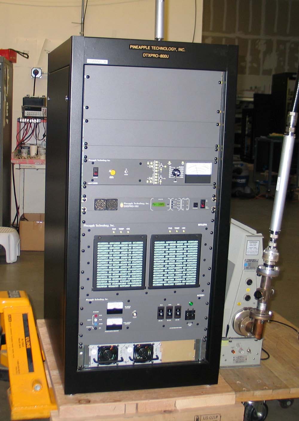
PW2DTXPRO800U
Mar 01, 2011800 W DTV TRANSMITTER
Equipment Class
TBC - Licensed Broadcast Station Transmitter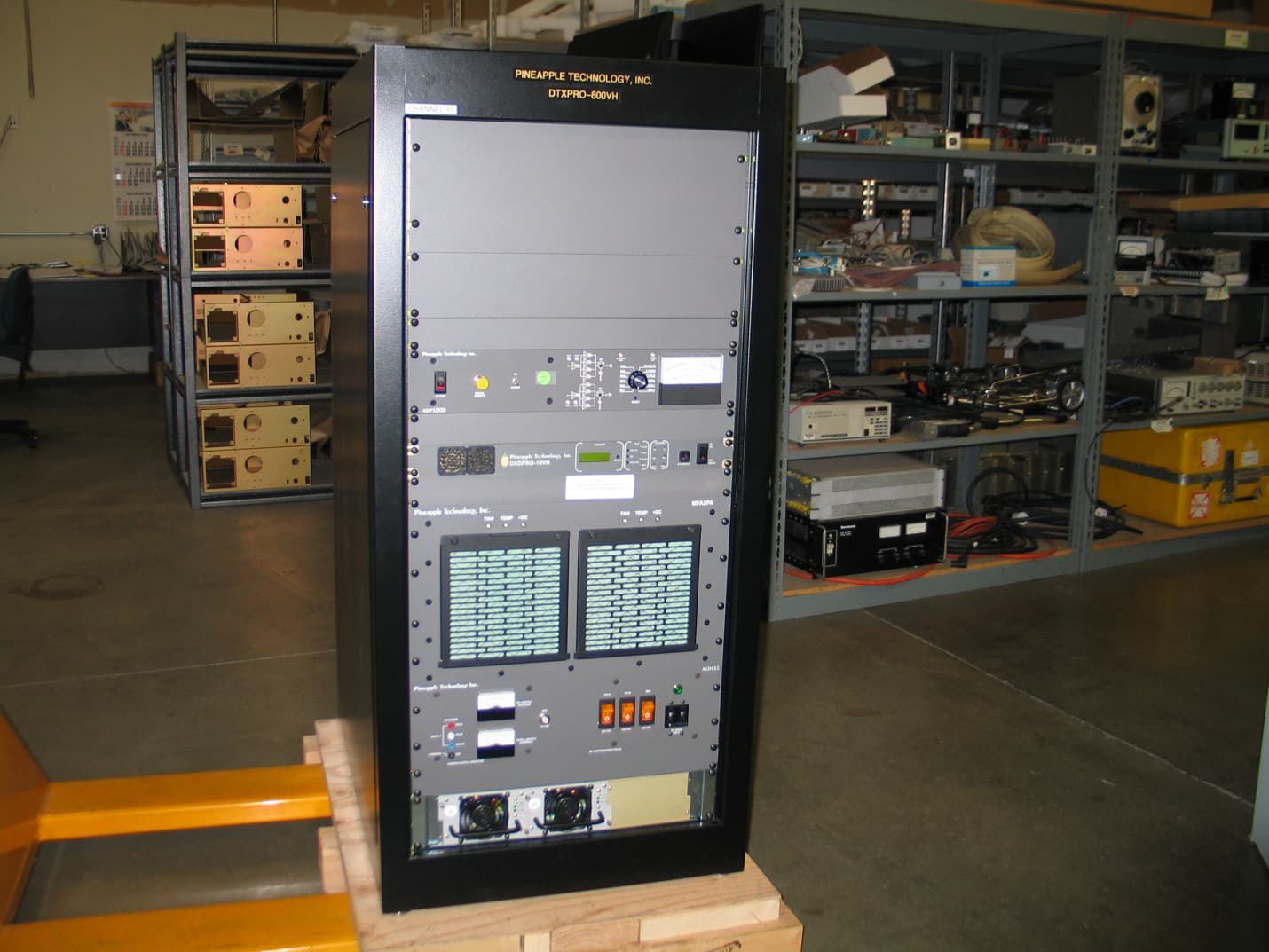
PW2DTXPRO800VH
Feb 27, 2011800 WATT DTV TRANSMITTER
Equipment Class
TBC - Licensed Broadcast Station Transmitter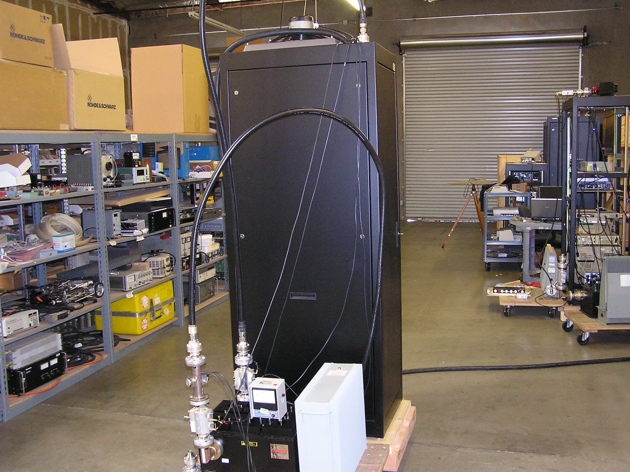
PW2DTXPRO1200U
Dec 12, 20101.2 KW DTV TRANSMITTER
Equipment Class
TBC - Licensed Broadcast Station Transmitter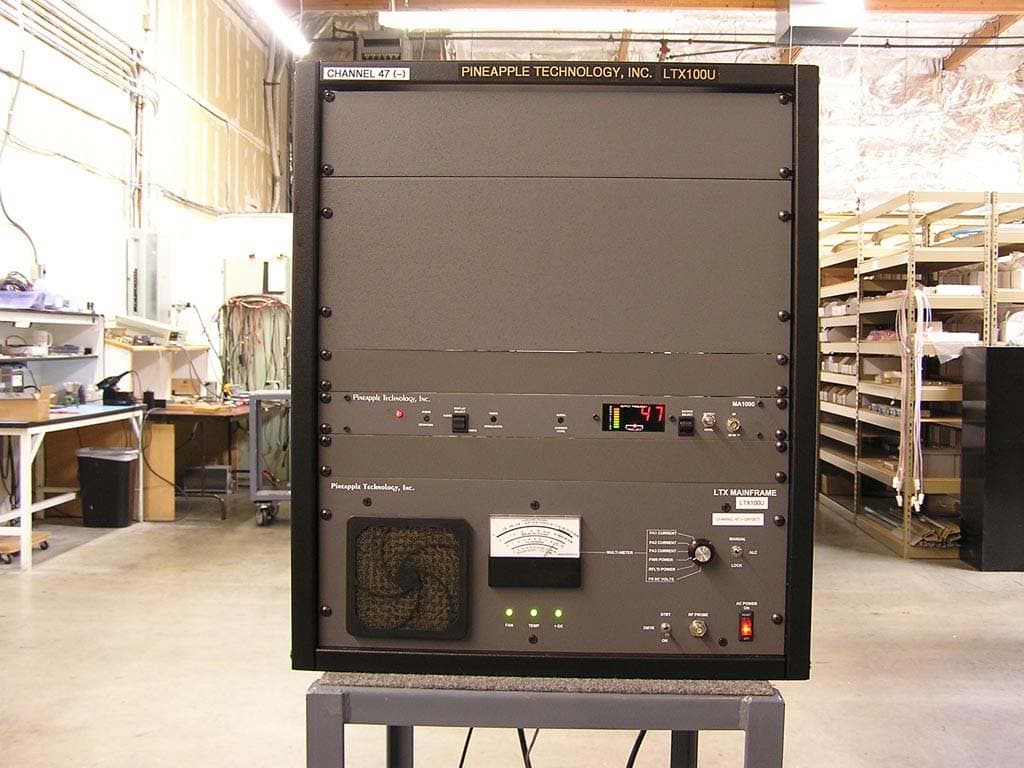
PW2LTX100U
May 14, 2007100 WATT TV ANALOG BROADCAST TRANSMITTER
Equipment Class
TBC - Licensed Broadcast Station Transmitter