PW2LTX100U100 WATT TV ANALOG BROADCAST TRANSMITTER
Pineapple Technology, Inc.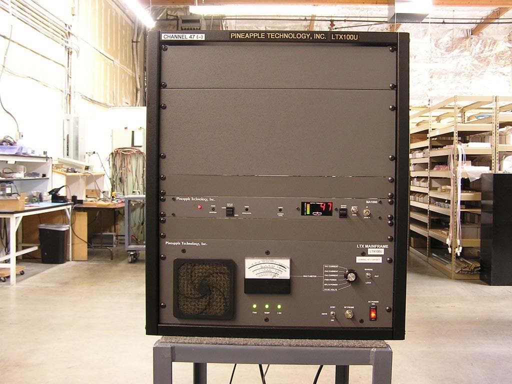
Click to zoom
Application Details
- Equipment Class
- TBC - Licensed Broadcast Station Transmitter
- Date of Grant
- May 14, 2007
- Application Purpose
- Original Equipment
- Date of Application
- Mar 06, 2007
- Equipment Note
- 100 WATT TV ANALOG BROADCAST TRANSMITTER
- Frequency Range
- 614.00000000 - 806.00000000
- Company
- Pineapple Technology, Inc.
- Country
- United States
Documents & Files
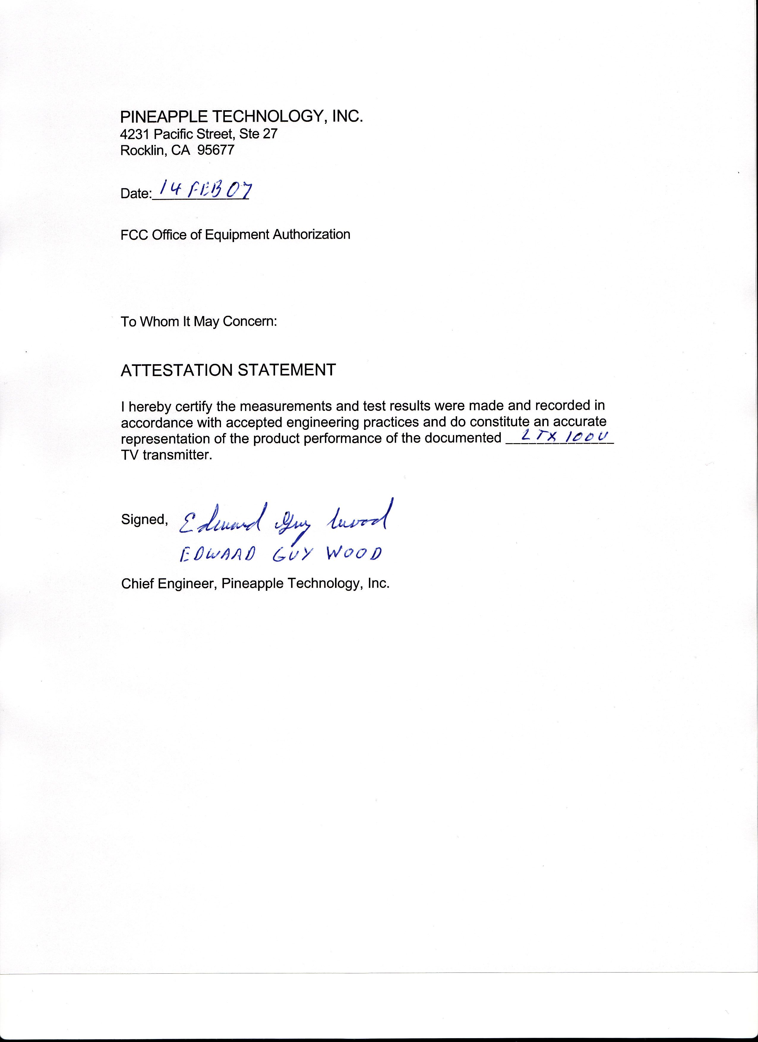
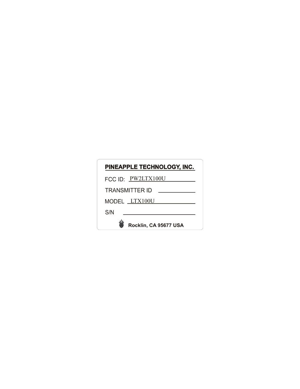
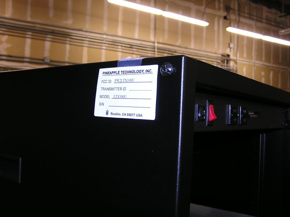
Document Text
Text extracted from the exhibit documents filed with the FCC. Open a document above to read the original.
Users Manual
LTX100U/VH/VL TRANSMITTERS INSTRUCTION MANUAL PINEAPPLE TECHNOLOGY, INC PINEAPPLE TECHNOLOGY, INC. LTX100U/VH/VL Operating and Service Manual TABLE OF CONTENTS Section l --- SAFETY NOTICES .................................................................................... 2 ** READ THIS SECTION BEFORE INSTALLATON * * Secton ll --- TRANSMITTER SPECIFICATIONS ............................................................... 3 Section lll --- TRANSMITTER INSTALLATION ............................................................ ... 5 Section lV --- TRANSMITTER TURN-ON ........................................................................ 6 Section V --- THEORY OF OPERATION A. Introduction ..........................................................................................8 B. MA1000 Modulator................................................................................. ...8 C. LTX Mainframe Assembly ........................................................................8 D. BPU150/BPLV750/BPHV750 Broadband Filter............................................. ...9 SECTION Vl --- SCHEMATIC AND PARTS LISTS A. LTX100U/VH/VL......................................................................................... 10 B. LTX Mainframe Assembly........................................................................ ...14 C. BPU150/BPLV750/BPHV750 Broadband Filter............................................. ...21 SECTION Vll --- RECOMMENDED ROUTINE MAINTENANCE .......................................... 23 SECTION Vlll --- ADJUSTMENTS AND TUNING ............................................................ 24 SECTION lX --- PROBLEM SOLVING / TROUBLESHOOTING ....................................... ... 25 SECTION X --- WARRANT Y ....................................................................................... 27 Section I Safety Notices PINEAPPLE TECHNOLOGY, INC. LTX100U/VH/VL Operating and Service Manual l --- SAFETY NOTICES l ---SAFETY NOTICES ** READ THIS SECTION BEFORE INSTALLATION ** SEVERE ELECTRICAL SHOCK OR BURNS MAY OCCUR IF THIS EQUIPMENT IS USED IMPROPERLY. NEVER WORK ON THIS EQUIPMENT ALONE. ALWAYS HAVE ANOTHER PERSON PRESENT WHILE WORKING ON ELECTRICAL CIRCUITS OR MOVING EQUIPMENT. COMMUNICATIONS TO EMERGENCY SERVICES SHOULD BE AVAILABLE AT ALL TIMES. BEFORE CONNECTING THIS EQUIPMENT TO ANY AC ELECTRICAL SOURCE READ THE SECTION ON INSTALLATION. ALL ELECTRICAL WIRING FOR THIS EQUIPMENT MUST BE PERFORMED BY QUALIFIED ELECTRICIANS. ALL WIRING MUST BE COMPLIANT WITH LOCAL ELECTRICAL CODES. POWER AMPLIFIERS AND SUPPLIES ARE HEAVY. TO INSTALL THIS EQUIPMENT IN RACKS USE TWO (2) PERSONS TO AVOID POSSIBLE INJURIES. NEVER OPEN THE CABINET ENCLOSURE OR UNPLUG CABLES OR WIRES WHILE THIS EQUIPMENT IS OPERATING. ALL SERVICE WORK MUST BE PERFORMED BY QUALIFIED TECHNICIANS ONLY . IF ONE IS NOT AVAILABLE LOCALLY, CONTACT PINEAPPLE TECHNOLOGY, INC. FOR A LIST IN YOUR AREA. Page 2 Section II Transmitter Specifications THESE SPECIFICATIONS ARE SUBJECT TO CHANGE WITHOUT NOTICE. PINEAPPLE TECHNOLOGY, INC. LTX100U/VL/VH Operating and Service Manual II – TRANSMITTER SPECIFICATIONS II – LTX100U/VL/VH SPECIFICATIONS OPERATING Power Output .............................. 100 Watts P-Sync 5 Watts Aural RF Output Impedance..................... 50 ohms Frequency Range LTX100U...........................470 – 806 MHz LTX100VL.........................CH 2 – CH 6 LTX100VH.........................CH7 – CH13 Frequency Stability........................ 1 PPM or better Harmonic and Spurious..................... -50 db Power Consumption........................ 500W maximum AC Line Voltage........................... 85 – 120 VAC Single Phase VIDEO PERFORMANCE Visual Frequency Response............... +/- 1 db across the TV channel -1.25 MHz to 4.75 Mhz relative to visual carrier. Differential Gain...................................< 7% Low Frequency Linearity....................... < 15% Group Delay...................................... Meets FCC Part 73 Rule Video Input Impedance......................... 75 ohms Video Input Level................................ 1 volt p-p Variation of Output Power...................... < 5% Regulation of Output Power.................... < 5% typical Video Signal to Noise Ratio.................... < 45 db un-weighted Page 3 THESE SPECIFICATIONS ARE SUBJECT TO CHANGE WITHOUT NOTICE. PINEAPPLE TECHNOLOGY, INC. LTX100U/VL/VH Operating and Service Manual II – TRANSMITTER SPECIFICATIONS AUDIO PERFORMANCE Audio Response............................. Meets FCC Pre-emphasis curve Distortion...........................................< 1% THD FM Noise............................................. < 50 dB or better AM Noise..........................................< 40 dB or better AM Synchronous Noise......................... < 40 dB typical GENERAL Operating Temperature.......................... -10 to +35 Degrees Celsius Ambient +14 to +95 Degrees Fahrenheit Ambient Altitude............................................ 5,000 ft without additional cooling Cooling Requirement............................ Built in, except where noted Connectors.........................................BNC Connector Input, N Connector Output Weight.............................................100 lbs Dimensions Overall..............................21” x 25” x 24” (W x H x D) Standard Page 4 Section III Transmitter Installation PINEAPPLE TECHNOLOGY, INC. LTX100U/LV/LH Operating and Service Manual lll -- TRANSMITTER INSTALLATION lll -- TRANSMITTER INSTALLATION To ensure long and reliable trouble-free service from the LTX100U/LV/LH transmitters the following steps for installation are recommended: 1. MECHANICAL INSTALLATION:The LTX100U/LV/LH transmitters were designed to be installed in a building protected from the weather. The building should have a hard-surface floor such as concrete with a moisture barrier. This barrier could be pressure-treated wood sub flooring which could be anchored to the concrete and to the tr…
Text truncated - open the document above for the full version.
External Photos
LTX100U EXTERNAL CONSTRUCTION PHOTOGRAPHS FRONT VIEW RIGHT VIEW LEFT VIEW
Internal Photos
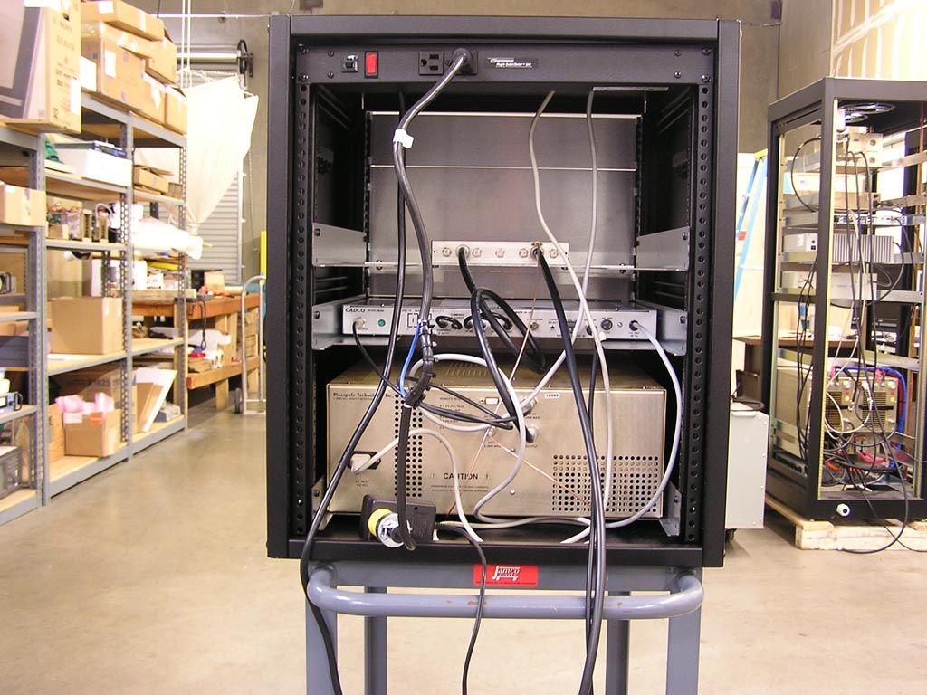
LTX100U INTERNAL CONSTRUCTION PHOTOGRAPHS REAR VIEW
Operational Description
PINEAPPLE TECHNOLOGY, INC. LTX100U/VL/VH Operating and Service Manual V -- THEORY OF O V. THEORY OF OPERATION (CONTINUED) (Page 2 of 2) D. BAND PASS FILTERS BPU150N - Used in the LTX100U UHF Transmitter BPVH300N - Used in the LTX100VH High VHF Band (Ch 7 - 13) Transmitter BPVL200N - Used in the LTC100VL High VHF Band (Ch 2 - 6) Transmitter These Band Pass filters were designed to meet FCC Certification requirements with minim RF Power. They come tuned and tested to the operating frequency of the transmitter and should not be adjusted without proper equipment. Replacement filters are available a s from Pineapple Technology, Inc. upon request. OPERATION mum loss of s
Parts List/Tune Up Info
PINEAPPLE TECHNOLOGY, INC. LTX100U/VL/VH Operating and Service Manual Vl -- SCHEMATICS AND PARTS LIST A. LTX100U ASSY TREE Item Qty Type P/NTitleDetail TopCAT LTX100ULTX SERIES UHF TRANSMITTER 100 WATTS 11PLLTXMAINFRAME UH FLTX SERIES XMTR 100 W UHF BASIC UNIT 21CAT MA1000M369 CADCO MODULATORMODIFIED TO PTI SPECS 31PSBPU150NBP FILTER 150 W UHF470-862 MHz 41PSMFR13RUEQUIPMENT RACK 13 RUBLK 19 IN DEEP 769945
Parts List/Tune Up Info
PINEAPPLE TECHNOLOGY, INC. LTX100U/VL/VH Operating and Service Manual Vl -- SCHEMATICS AND PARTS LIST A. LTX Mainframe UHF Assy Tree Item Qty Type P/NTitleDetail 11PLLTXMAINFRAME UH FLTX SERIES XMTR 100 W UHF BASIC UNIT 11PSMF9529ALTX HEAT SINK HOLDERAL 090 21PSMF9531ALTX FRONT PANEL0125 AL W/PAINT AND SILK 31PSMF9532ALTX CHASSIS090 AL ALODYNE W/REAR SILK 41PSMF9533ALTX AIR DAM DEFLECTOR050 AL ALODYNE 51PSMF9534ALTX TOP COVERO60 AL ALODYNE 61PLMF9535LTX100U HEAT SINKSTD HEAT SINK W/U250LD FP 101PSPC9515COUPLER GP COVER TMM3 012 USE ON ALL -30dB COUPLERS 111PSPC9514UHF -30 dB COUPLER TMM3 012 DUAL DIRECTIONAL 141PS660104LTX MULTI-FUNCTION METERHOYT MODEL 3135 ANALOG MTR 151PSAC3108CIRCUIT BREAK/ ON/OFF SWIT C115 VAC 10 A RESETABLE 161PSAC1003FILTER, AC LINE110/220 AC PLUG 171PS990200FILTER, AIR DRYCOMAIR FILTER/GUARD ASS,Y 181PS851035FAN AC 115 100 CFM 115 VACCOMAIR-ROTRON MUFFIN XL AC MX2 A 191PSCA5110CABLE ASSEMBLY 10 WIRE10 WIRE SOC TO SOC CONNECTOR 204PS480300CON 2 PIN HEADERAMP A23837-ND 221PSAC2010DC POWER SUPPLY 115/220 VA C320 WATTS 27-31 VDC 236PSINHOUSE_LABORPTI LABOR LOADED 248PSINHOUSE-ENG TES TENG TESTING AND FIXITLOADED 251PL1A0300LTX100 METERING CIRCUITFRONT PANEL ASSEMBLY 261PL1A0027PWR MONITOR CKPC9052B CBR 271PL1A0035PA STATUS BOARDPC9061H 281PL1A0026VSWR/PWR DET BRDPC9051A 291CAT DRV10-40DRIVER AMP WITH ALC CKT PO 10 W 341PS990280FINGER GUARD 6"FINGER GUARD 150MM METAL 351PS851030PATRIOT AC FAN 110 VXL100 EXHAUSE FAN 361PS481501 AURAL FEMALE PNL CONNECTOXLR TYPE 3 PIN 371PS481502AURAL MALE PLUE XLR3 PIN 769946
Schematics
Band Pass Filter AC Inlet AC Inlet Video In Audio In RF Input RF Output Mon RF Probe Remote Interface Video Audio MA1000 Modulator Band Pass Filters BPU150N used for L TX100U BPVH300N used for L TX100VH BPVL200N used for L TX100VL LTX100( ) Mainframe Assembly LTX100U/VH/VL UHF Transmitter A B 1 1:1 DB9 SIZE FSCM NO. SCALE SHEET DWG NO . REV Pineapple Technology , Inc. Rocklin, CA 110 VAC
Schematics
SIZE FSCM NO . SCALE SHEET DWG NO . REV Pineapple Technology , Inc. Rocklin, CA LTX100 Mainframe Assembly A 1 B 1:1 Directional Coupler CAL CAL ATT ATT R F AC Inlet 110 VAC DC Output Driver M +DC RF IN PA Fan PS1 P/S 110VAC ON\OFF SW PA M +DC RF IN DC Metering and DC Monitoring 1A0035 RF Deck 110 VAC RF DB9 From RF Output Monitor Ta p RF RF Probe FWD Pwr P1 P2 P3 Gnd P4 Shutdown P5 P6 RFLD Pwr P7 ALC P8 +8 VDC P9 LTX100U Ch 14 - 69 Channel Driver Direct’l Coupler PA P/S UDR10E PC9512 PC9513 PC9514 U250LD Note1 Note1 Note1 VH250LD VL500A UDR10E UDR10E Ch7-13 Ch2-6 LTX100VH LTX100VL
Schematics
SIZEFSCM NO. SCALE SHEET DWG NO.REV Pineapple Technology, Inc. Rocklin, CA 1A0035 STATUS BOARD CIRCUIT DIAGRAM SECTION VI - SCHEMATICS AND PARTS SUB-SECTION VI.A - LTX25U
Test Report
TEST REPORT PINEAPPLE TECHNOLOGY INC. LTX100U TV TRANSMITTER TECHNICAL REPORT INTRODUCTION The following information is provided to support the technical performance of the Pineapple Technology LTX100U TV Transmitter. The information is supplied for broadcast TV service according to applicable portions of FCC rules contained in Part 2, Part 73, and 74. The test report is comprised of tests made upon channel 47. However, since there are no frequency dependent parts within the transmitter (the final transmitter filter is tunable per channel and ordered on a per channel basis) the test report constitutes an accurate and representative sample of the transmitter performance anywhere in the approved frequency range of 470-608 MHz and from 614-806 MHz. 1. Power Output Measurements as indicated by FCC Rule Part 2.1046. 2. Frequency Measurements as identified by FCC Rule Part 2.1055. 3. Visual Frequency response measurements of the transmitter to be within the window specified by FCC Rule Part 74.750. 4. Occupied BW of aural signal specified by FCC Rule Part 2.1079. 5. Aural frequency response as identified by FCC Rule Part 73.687 6. Measurement of conducted harmonics and spurs +/- 3 MHz outside of channel as specified by FCC Rule Part 74.750 and Part 2 Rule 2.1051. 7. Measurement of cabinet radiation of spurs and harmonics as specified in FCC Rule 2.1053 and 2.1057. 8. Measurements of voltage and current to final amp stage as outlined in FCC Rule 2.1033. Measurements were conducted at the transmitter visual power output level of 100 watts peak of sync (W ps ) for which type certification is sought. The corresponding aural power level is 5 watts. Measurements were taken on a unit with visual carrier frequency of 669.24 MHz and an aural carrier frequency of 673.74 MHz. (This transmitter is operating on CH 47 with a negative 10 kHz offset). The test equipment used for the measurements on the next few pages is listed at the end of the test report. All test equipment was calibrated prior to the use of the equipment by the supplier of the test equipment. RF POWER OUTPUT The equipment was configured as shown in Figure 1. The loss through the directional coupler was calibrated at the operating frequency (671.0 MHz). The TSG-90 video generator was configured to produce a signal with 0 IRE video and sync. The aural carrier was not energized. The visual portion of the transmitter was energized to the desired output power (0.1 kWps). The power was read on the HP-435B Power Meter. The video demodulator and 1750 were used to verify that sync compression was not causing distortion of the measurement. The aural carrier was energized and its output level was then raised to meet the precise 13 dB visual/aural power ratio as observed on the spectrum analyzer. Pictures were also taken of demodulated video with two (2) lines of a modulated stair step (or reference white level) , and two (2) fields of video to verify no signal distortions were present at the 0.1 kW power level where certification is being sought. HIGH POWER OUTPUT HP 435B Power Meter reading -3.75 dBm Loss in directional coupler 51.5 dB Sum 47.75 dBm = 59.5 W Avg Peak of sync power = 1.68 times average power under the following conditions: 0 IRE (Black) picture No aural carrier 40 IRE of sync Proper sync to video ratio (40/100) and depth of modulation, this is shown by the two line modulated stair step display. 59.5 W Avg. X 1.68 = 99.96 W peak of sync (Within 0.1 dB of 100 W) The aural carrier was set 13 dB lower. 100 W ps = 50 dBm minus 13 dB equals 37 dBm = 5 W Aural Power DC voltage and current to final amplifier stage is: 7.6 Amps at 32 VDC measured with black level input. Fig. 1 Meter indicating -3.75 dBm for visual RF Power Output Fig. 2 Two Lines of video showing proper Modulation depth Fig.3 Two Fields of video showing proper Modulation depth List of test equipment model and serial number The following test equipment was used in the various test equipment configurations or to create calibration of equipment at various frequencies. All equipment was known to be in good working order and the supplier of the equipment stipulated the equipment was within the calibration period. EQUIPMENT MODEL SERIAL NUMBER A.R.D. Technology LPD-1001 Log Periodic Antenna 18731 Agilent 53131A Frequency Counter KR01204459 Bird 8329-300 2000W 30 dB Attenuator 506 ETS 3147 Log Periodic Antenna 9112-1053 Fluke 77 Meter 54810424 HP 339A Distortion Analyzer 2520A08480 HP 8590B Spectrum Analyzer 3009A0840 HP 8595E Spectrum Analyzer 3523A01399 Modulation Sciences MSI320 Demodulator 390128364 Narda 768-20 20W 20dB Attenuator N/A Tektronix 1410 Video Generator B020216 Tektronix 1750 Waveform Monitor B033351 Tektronix TSG90 Video Signal Generator B022622 Tektronix VM700A Video Analyzer B041249
Test Report
FREQUENCY STABILITY MEASUREMENTS (NTSC) The exciter used for this transmitter is the same model of exciter used in the type certified UTX-2K Ultra transmitter with FCC ID PW2UTX2KULTRA. Therefore, the frequency stability measurements from that transmitter exciter are repeated here for inclusion and completeness. Frequency stability versus temperature and line voltage were measured in a controlled environment. For these tests the exciter RF output was fed to a frequency counter that has better than 1ppm accuracy. The test equipment configuration is shown below. The variac was adjusted for nominal voltage and the frequency was recorded. Then the variac was adjusted to 85% and 115% of the nominal voltage and the frequency was recorded at each voltage level. For this test, the -10 kHz offset was used. The results are tabulated below. LINE VOLTAGE (Volts) Visual Frequency (MHz) Aural Frequency (MHz) 100 (85%) 507.239979 511.739882 121 (nominal) 507.239979 511.739882 140 (115%) 507.239979 511.739882 For the temperature stability measurements the exciter was placed inside a Tenney temperature chamber equipped with a MicroTenn II temperature controller. The exciter frequency was measured on the frequency counter. The temperature in the chamber was changed to each of the points identified in the table below. The chamber followed a prescribed rate to change the temperature and then the temperature was allowed to stabilize at the temperature for 10-15 minutes. When the temperature had stabilized, the exciter visual and aural frequencies were recorded, and then the temperature was advanced to the next measurement point. The temperature was measured first at room temperature and then raised to +50 °C, allowed to stabilize for 15 minutes and then cycled to each colder temperature measurement point. Temperature °C Time Visual Frequency (MHz) Aural Frequency (MHz) 25 1:30 507.250,000 511.749,913 50 2:50 507.249,793 511.750,038 40 3:10 507.249,781 511.749,818 30 3:20 507.249,955 511.749,877 20 3:30 507.249,885 511.749,770 10 3:45 507.249,577 511.749,407 0 4:00 507.249,434 511.749,343 -10 4:10 507.249,523 511.749,397 -20 4:20 507.249,567 511.749,816 -30 4:30 507.249,613 511.750,255 From the measurements above, it is apparent that the FCC rules in Part 2.1055 and in Part 74 are met. Exciter Frequency Counter Variac AC Input AC OutputRF Output Exciter Frequency Counter Temperature Chamber RF Output
Test Report
1 Tested By: Ed Wood Date: 14 Feb 07 VISUAL TRANSMITTER FREQUENCY RESPONSE MEASUREMENTS The test equipment configuration of Figure 1 was used with the 1410 video generator supplying the video input waveform. For this test, the aural carrier was left energized. A variable frequency sine wave sweep of 90 IRE Peak-to-Peak amplitude from 100 kHz to 6.0 MHz with pedestal set at 52.5 IRE input video waveform was used. The modulation output was increased until the maximum excursion reached reference white and 10 IRE as shown in the photos in Fig. 4 and Fig. 5 below. The RF sideband output level was measured for the sidebands below and above the visual carrier. The frequency response was displayed on the HP Spectrum Analyzer. The spectrum plot, showing markers at the Visual Carrier and at 4.75 MHz ( 51 dB down from Visual Carrier ), is displayed in Fig. 6 to confirm that the radiated envelope meets the requirements as outlined in FCC Part 74 Rule 750. FREQUENCY RESPONSE INPUT WAVEFORMS Fig. 4 - Two (2) Horizontal Lines 2 Fig. 5 – Two (2) Fields The photograph of the spectrum analyzer display below demonstrates compliance with FCC 74.750. Fig. 6
Test Report
OCCUPIED BANDWIDTH MEASUREMENTS The test equipment was configured as in Figure 1. The aural carrier was energized and increased in power until the desired visual to aural ratio of 13dB (5%) was met. The visual waveform used was a 0 IRE video input level from the TSG-90 and the aural input signal was a 15kHz sine wave taken from the HP339A Distortion Measurement Set. The aural deviation was increased until the desired level (85% of 25kHz =21.25 kHz) was indicated by the HP339A Distortion Measurement Set monitoring the calibrated deviation output (25mV/kHz) of the MSI 320 Precision Video Demodulator. The output spectrum was observed on the HP Spectrum Analyzer noting the requirements as identified in FCC Rule Part 2.1079. As can be observed, the output waveform meets these requirements. OCCUPIED BANDWIDTH- POWER OUTPUT =0.1 kW ps (Scan width = 200kHz) Fig. 7
Test Report
AURAL FREQUENCY RESPONSE The equipment configuration of Figure 1 was used. The visual and aural carriers were energized and the aural carrier was modulated by the HP 339A Distortion Measurement Set. The visual input waveform used was a “0” IRE video input level from the TSG-90. A reference level was set at 100Hz and the audio generator level was adjusted to achieve 25kHz deviation at each modulating frequency using the calibrated audio output (25mV/kHz into 75 ohms) from the MSI 320 TV demodulator. The following table of audio response was obtained by dividing the output audio level by the input level. This table is plotted on the graph shown below. The adjustment of -1 dB was used to center the plot within the graph. FREQUENCY RESPONSE DATA TABLE Frequency (Hz) Raw Level (dB) Adjustment (dB) Level (dB) 50 0.0 -1 -1.0 100 (Reference) 0.0 -1 -1.0 200 0.0 -1 -1.0 400 0.2 -1 -0.8 800 0.6 -1 -0.4 1k 1.0 -1 0.0 2k 2.5 -1 1.5 4k 6.3 -1 5.3 8k 11.2 -1 10.2 10k 12.5 -1 11.5 15k 15.2 -1 14.2 Chart 1
Test Report
1 Tested By Ed Wood Date: 14 Feb 07 CONDUCTED SPURIOUS AND HARMONICS The following photographs indicate the spurious performance (> +/- 3 MHz) from the designated TV channel. As can be seen from the photo taken at 100 W, the spurious levels are below 60 dB relative to the peak of sync of the visual carrier. The top of the display indicates the true peak of sync value when the vertical interval portion of the picture is present. The photo in Fig. 8 shows the desired 13 dB visual to aural power ratio. Fig. 8 CONDUCTED HARMONIC OUTPUTS The following data indicates the harmonic performance of the LTX100U. Only the 2 nd harmonic was visible. The following table displays the actual value of the harmonic that takes into account the coupling factor of the directional coupler and loss of the cable used for the measurement. There was no value recorded when the measured value was <-75 dB relative to the visual peak of sync value as this was below the noise floor of the spectrum analyzer with the bandwidth used. Photographs of the spectrum containing the second harmonic are shown below. The pictures indicate that the harmonic levels are well below 60 dB compared to the top of the display which represents visual sync peak power. 2 HARMONIC LEVELS VERSUS FREQUENCY AT Pout=100 W FREQUENCY OF HARMONIC (MHz) AMPLITUDE (Relative to visual Peak Sync at fundamental frequency (dB)) 1338.48 (2 nd harmonic) -63 dB 2007.12 (3 rd harmonic) ** dB 2676.96 (4 th harmonic) ** dB 3346.2 (5 th harmonic) ** dB 4015.44 (6 th harmonic) ** dB 4684.68 (7 th harmonic) ** dB 5353.42 (8 th harmonic) ** dB 6023.16 (9 th harmonic) ** dB 6692.4 (10 th harmonic) ** dB ** Note: Amplitude at or below the noise floor of -75dBc Photo of 2 nd Harmonic Spectrum Fig. 9 The photograph in Fig. 9 is centered at the 2 nd Harmonic because only that harmonic was possibly visible. The fundamental frequency visual peak of sync reference value is located at the top of the screen on this photograph. The values indicate a maximum harmonic level of -63 dB when corrected for coupling and cable loss. 3 Fig. 10 The photograph in Fig. 10 is centered at the 3 rd Harmonic showing the noise floor at around -75 dBc when corrected for coupling and cable loss. The fundamental frequency visual peak of sync reference value is located at the top of the screen on this photograph.
Test Report
CABINET RADIATION The transmitter and test equipment were configured as shown below including the angles of measurement with respect to the transmitter cabinet. The photo on the subsequent page also shows the physical set-up of the test equipment and equipment under test. The transmitter was operating at 100W peak sync power with a 13dB visual/aural ratio with the video input signal being a sync signal and 50 IRE “set-up” level. The free space path loss, cable loss and antenna gain characteristics were obtained at the fundamental frequency and at each of the harmonics of the visual carrier frequency in order to accurately assess the level of the signal radiated from the cabinet. Radiation from the cabinet was measured at a distance of 30 feet in 4 different physical rotation angles: 0, 90, 180 and 270 degrees ( 0 degrees being the front of the cabinet). All spectral components above -80 dB referenced to peak sync power radiated from the cabinet were recorded. The values are tabulated in the table on the next page following the photo. PHYSICAL CABINET RADIATION TEST CONFIGURATION This photograph shows the actual laboratory environment in which the cabinet radiation tests were conducted. The log periodic antenna, cable and spectrum analyzer are shown in the foreground and the LTX100U is shown in the background. The transmitter was rotated 90 degrees for each of the measurement orientations. As calculated from the spreadsheet data on the following page, the worst case measurement was -64 dBm at the second harmonic (The photo above shows this particular measurement). The measurement tables for the remaining views of the transmitter are shown on the following pages. LTX100U Xmtr Pineapple Technology Inc. CABINET RADIATION TEST TEST INPUTS CONDITIONS & PARAMETERS TEST DATE: 3/12/2007 TEST ENGINEER: Jim Collier TRASMITTER MODEL NO: LTX100U OPERATING POWER OUTPUT LEVEL 50.0 dBm 100 Power in Watts OPERATING FREQUENCY IN GHz 0.66925 gHz 47 Channel ANTENNA MODEL NUMBER ETS 3147 S/N 9112-1053 SPECTRUM ANALYZER MODEL 8595E DISTANCE TO TRANSMITTER IN METERS 10 METERS FRONT VIEW Harmonic Frequency SIGNAL CABLE ANTENNAPATH ADJ MAXIMUM STATUS LEVEL LOSS dB GAIN dB LOSS dBLEVEL LEVEL P=PASS GHz dBm dB dB dB dBm dBm Fc 0.66925 -53 0.4 6.6 49.01 -10.1619 -10.0 N/A Fc*2 1.3385 -64 0.8 7.0 55.03 -15.2 -10.0 P Fc*3 2.00775 -79 1.1 4.3 58.55 -23.6369 -10.0 P Fc*4 2.677 -88 1.5 3.0 61.05 -28.4968 -10.0 P Fc*5 3.34625 -88 1.8 4.4 62.99 -27.6172 -10.0 P Fc*6 4.0155 -88 2.1 1.1 64.57 -22.3923 -10.0 P Fc*7 4.68475 -88 2.5 -1.3 65.91 -18.312 -10.0 P Fc*8 5.354 -88 2.8 1.9 67.07 -20.0109 -10.0 P Fc*9 6.02325 -88 3.2 2.1 68.10 -18.8465 -10.0 P Fc*10 6.6925 -88 3.5 2.1 69.01 -17.5901 -10.0 P RIGHT VIEW Harmonic Frequency SIGNAL CABLE ANTENNAPATH ADJ MAXIMUM STATUS LEVEL LOSS dB GAIN dB LOSS dBLEVEL LEVEL GHz dBm dB dB dB dBm dBm Fc 0.66925 N/A 0.4 6.6 49.01 N/A -10.0 N/A Fc*2 1.3385 -63 0.8 7.0 55.03 -14.2 -10.0 P Fc*3 2.00775 -78 1.1 4.3 58.55 -22.6369 -10.0 P Fc*4 2.677 -88 1.5 3.0 61.05 -28.4968 -10.0 P Fc*5 3.34625 -88 1.8 4.4 62.99 -27.6172 -10.0 P Fc*6 4.0155 -88 2.1 1.1 64.57 -22.3923 -10.0 P Fc*7 4.68475 -88 2.5 -1.3 65.91 -18.312 -10.0 P Fc*8 5.354 -88 2.8 1.9 67.07 -20.0109 -10.0 P Fc*9 6.02325 -88 3.2 2.1 68.10 -18.8465 -10.0 P Fc*10 6.6925 -88 3.5 2.1 69.01 -17.5901 -10.0 P REAR VIEW Harmonic Frequency SIGNAL CABLE ANTENNAPATH ADJ MAXIMUM STATUS LEVEL LOSS dB GAIN dB LOSS dBLEVEL LEVEL GHz dBm dB dB dB dBm dBm Fc 0.66925 N/A 0.4 6.6 49.01 N/A -10.0 N/A Fc*2 1.3385 -71 0.8 7.0 55.03 -22.2 -10.0 P Fc*3 2.00775 -79 1.1 4.3 58.55 -23.6369 -10.0 P Fc*4 2.677 -88 1.5 3.0 61.05 -28.4968 -10.0 P Fc*5 3.34625 -88 1.8 4.4 62.99 -27.6172 -10.0 P Fc*6 4.0155 -88 2.1 1.1 64.57 -22.3923 -10.0 P Fc*7 4.68475 -88 2.5 -1.3 65.91 -18.312 -10.0 P Fc*8 5.354 -88 2.8 1.9 67.07 -20.0109 -10.0 P Fc*9 6.02325 -88 3.2 2.1 68.10 -18.8465 -10.0 P Fc*10 6.6925 -88 3.5 2.1 69.01 -17.5901 -10.0 P LEFT VIEW Harmonic Frequency SIGNAL CABLE ANTENNAPATH ADJ MAXIMUM STATUS LEVEL LOSS dB GAIN dB LOSS dBLEVEL LEVEL GHz dBm dB dB dB dBm dBm Fc 0.66925 N/A 0.4 6.6 49.01 N/A -10.0 N/A Fc*2 1.3385 -65 0.8 7.0 55.03 -16.2 -10.0 P Fc*3 2.00775 -79 1.1 4.3 58.55 -23.6369 -10.0 P Fc*4 2.677 -88 1.5 3.0 61.05 -28.4968 -10.0 P Fc*5 3.34625 -88 1.8 4.4 62.99 -27.6172 -10.0 P Fc*6 4.0155 -88 2.1 1.1 64.57 -22.3923 -10.0 P Fc*7 4.68475 -88 2.5 -1.3 65.91 -18.312 -10.0 P Fc*8 5.354 -88 2.8 1.9 67.07 -20.0109 -10.0 P Fc*9 6.02325 -88 3.2 2.1 68.10 -18.8465 -10.0 P Fc*10 6.6925 -88 3.5 2.1 69.01 -17.5901 -10.0 P
Contact Information
Applicant
Robert Artigo(President)
Technical Contact
Greg Best Consulting, Inc.Greg Best
[email protected]816-792-2913
9223 N. Manning Avenue · Kansas City, Missouri · United States
Technical Specifications
| # | Rule Parts | Frequency Range | Power Output | Emission | Tolerance |
|---|---|---|---|---|---|
| 4 | 73,74 | 614 MHz - 806 MHz | 5 W | 250KF3E | 1000 Hz |
Other Applications from Pineapple Technology, Inc.

PW2DTXPRO10U
Aug 31, 201110 W DTV TRANSMITTER
Equipment Class
TBC - Licensed Broadcast Station Transmitter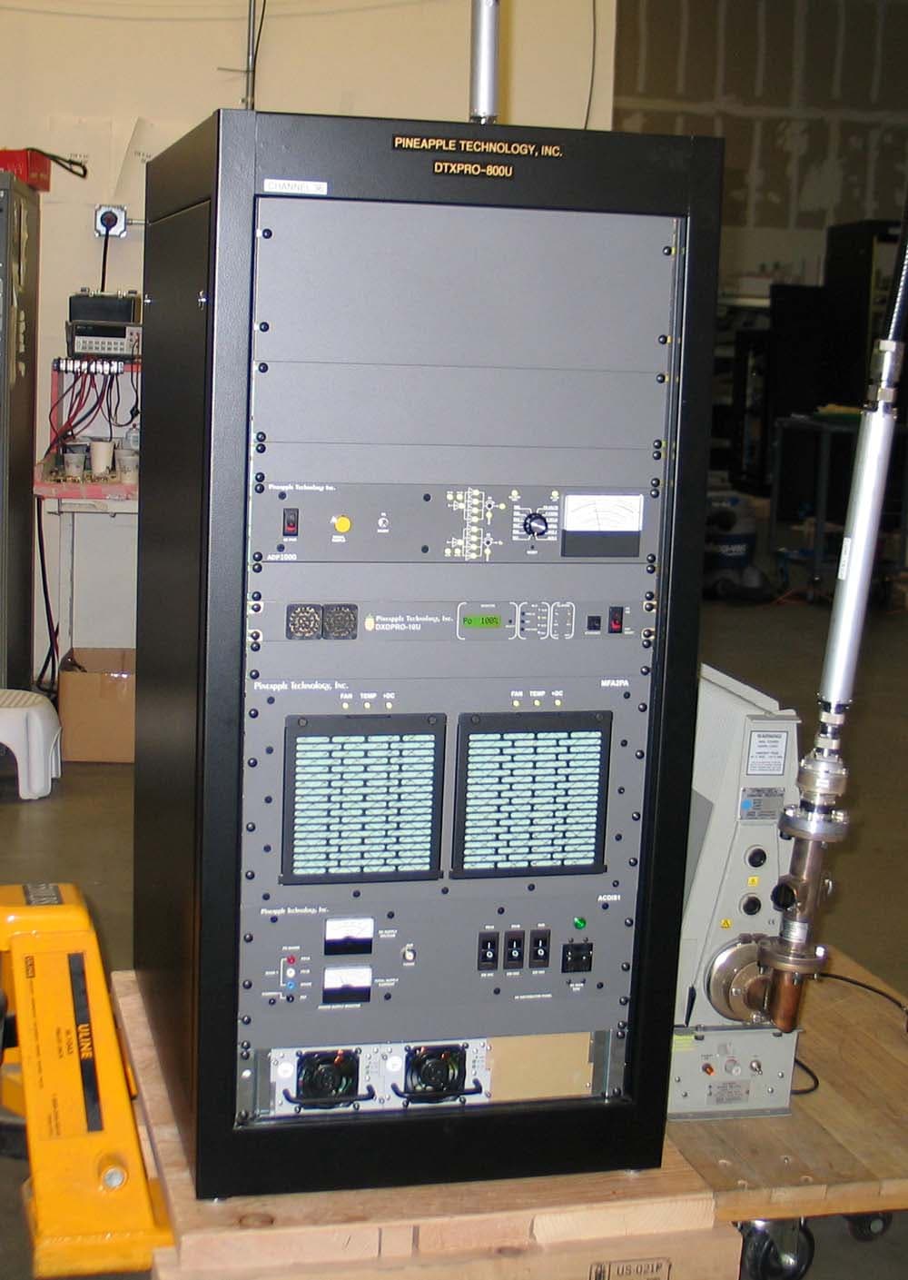
PW2DTXPRO800U
Mar 01, 2011800 W DTV TRANSMITTER
Equipment Class
TBC - Licensed Broadcast Station Transmitter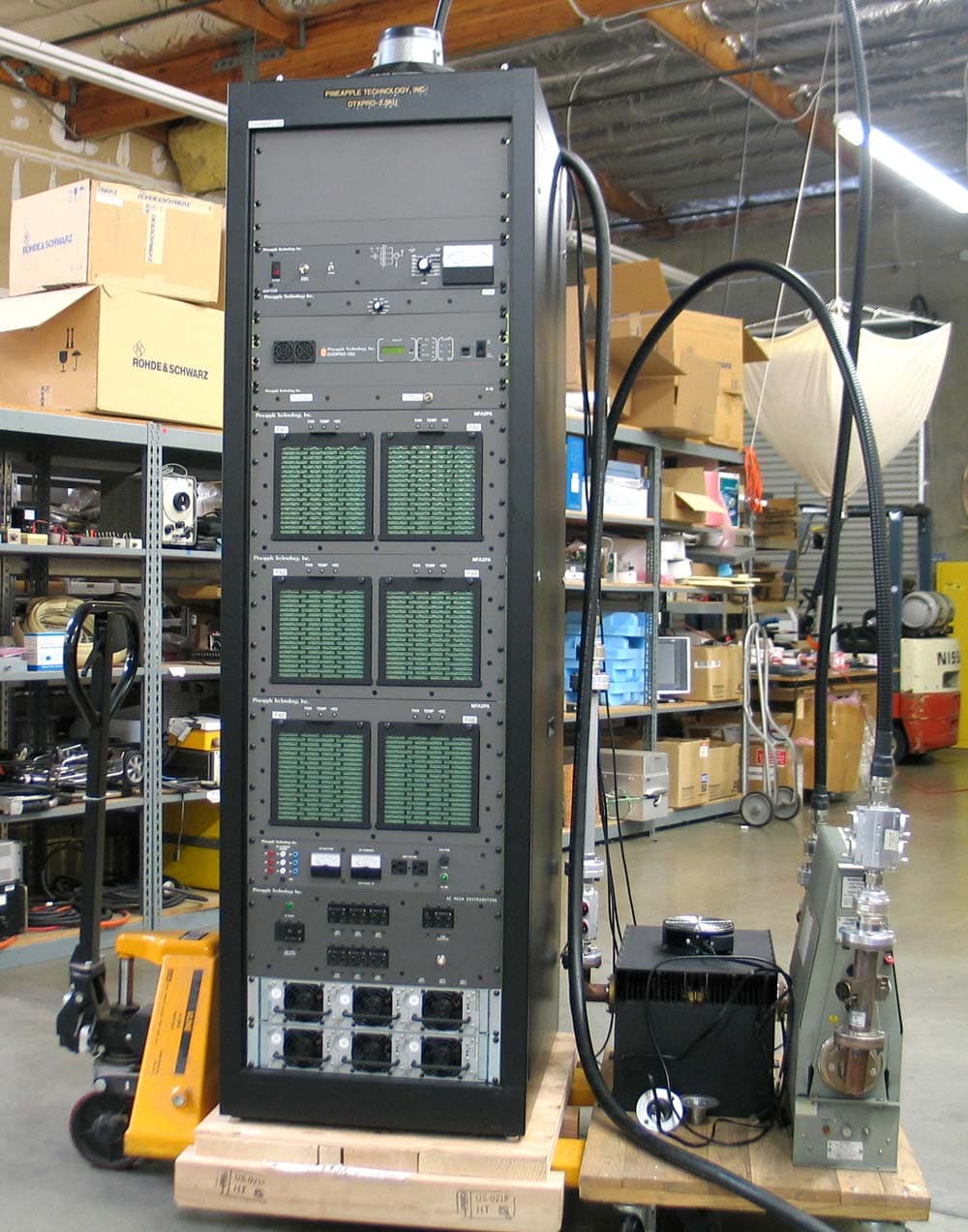
PW2DTXPRO2300U
Mar 01, 20112.3KW DTV TRANSMITTER
Equipment Class
TBC - Licensed Broadcast Station Transmitter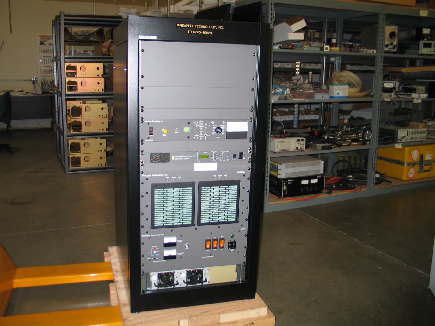
PW2DTXPRO800VH
Feb 27, 2011800 WATT DTV TRANSMITTER
Equipment Class
TBC - Licensed Broadcast Station Transmitter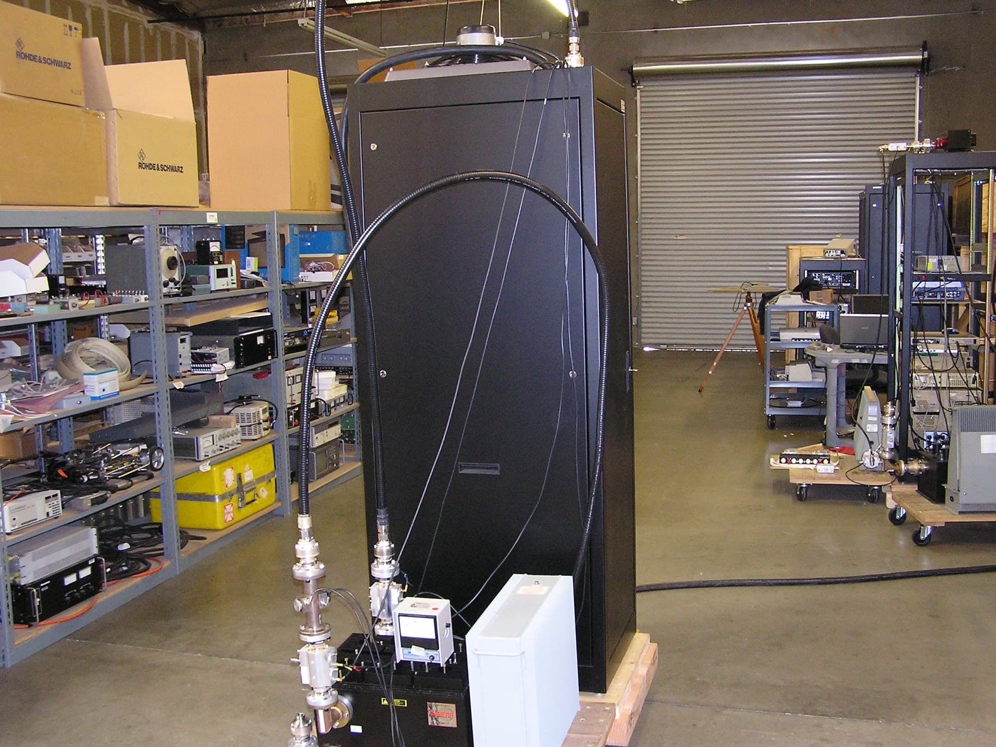
PW2DTXPRO1200U
Dec 12, 20101.2 KW DTV TRANSMITTER
Equipment Class
TBC - Licensed Broadcast Station Transmitter