PW2U106T-PROBroadcast Translator Retrofit Kit
Pineapple Technology, Inc.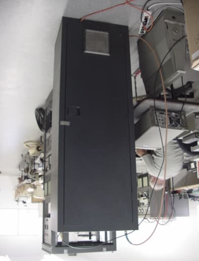
Click to zoom
Application Details
- Equipment Class
- AMP - Amplifier
- Date of Grant
- Feb 28, 2002
- Application Purpose
- Original Equipment
- Date of Application
- Oct 22, 2001
- Equipment Note
- Broadcast Translator Retrofit Kit
- Frequency Range
- 470.00000000 - 806.00000000
- Company
- Pineapple Technology, Inc.
- Country
- United States
Documents & Files
Document Text
Text extracted from the exhibit documents filed with the FCC. Open a document above to read the original.
Users Manual
UST106 Pro PREPARATORY MEASUREMENTS AND ADJUSTMENTS: The following adjustments are recommended to ensure that the transmitter is working properly before any changes are made. 1.Measure the output of the up-converter and be certain the level is set at +24dBm. The front panel Power adjustment knob should vary the +24 dBm by +1 to -4 dB only. If the output is out of range adjust the variable resistor (see the UST-106A instruction Manual) on the upconverter to insure that the proper range is maintained. This is important to protect the power amplifier from damage by overdrive. Over drive damage is not covered by warranty. 2.Measure the purity of the up-converted signal. This measurement is made to insure that the mixing products are at least -60dBc or better. The power amplifier is broadband and will amplify these unwanted signals making filtering necessary if they are out of specs to start with. 3.Adjust the aural/visual ratio to -13 dB (5%). This is a typical setting for most applications, however, the Power Amplifier can be used at higher levels if necessary with only minor degradation in performance. ***WARNING*** BEFORE REMOVING ANY PARTS OR WIRE, THE TRANSMITTER OR TRANSPOSER MUST BE TURNED OFF AND DISCONNECTED FROM THE PRIMARY AC POWER SOURCE. ALL OTHER EXTERNAL CONNECTIONS INCLUDING ANTENNA MUST BE DISCONNECTED. USE A GROUNDING ROD TO DISCHARGE ANY RESIDUAL CHARGES FROM THE HIGH VOLTAGE SUPPLY, CAVITY ECT. MOVE THE EQUIPMENT AWAY FROM OTHER EQUIPMENT SO THAT THERE WILL BE PLENTY OF ROOM TO WORK ON THE FRONT AND REAR OF THE EQUIPMENT TO BE MODIFIED. ***WARNING*** 1. Unplug translator, from external AC power. Turn off breaker for UST- 106A making sure all power is removed from transmitter before working on translator. 2.Open both front and back doors to ensure you have plenty of room to work. 3.Disconnect RF in and RF out cables from the tube and cavity apparatus. 4.Go to the rear of the translator and locate the high voltage wire. Cut the high voltage wire on the left side in the back of the translator at approximately 1 foot from the top of the cabinet just below the switch. 5.Go to the front of the translator. From the front of the translator unbolt the four bolts securing the tube and cavity apparatus from the front of the translator. 6. Gently pull off the tube and cavity and set it aside and save. 7.Move to the back of the translator. 8.Disconnect the RF Cables from the directional coupler. 9.Disconnect the RF output cable from the notch filter and pull the cable through the back of the translator. Pull the RF input cable that normally connects to the tube and cavity assembly through the back of the translator. It may be necessary to remove grommets in the back panel. 10.Disconnect all wiring to the blower motor. Unbolt it from the back of the translator, and remove it. 11.Remove the 3rd, 4th,and 5th nuts from the top of the rack on the right side. 12.Unbolt the notch filter and remove it from the translator. At this time all of the transmitter components that need to be removed from the TTC translator have been removed. Clean the dust and debris from the areas where parts have been removed. 13.Bolt the provided panel labeled “RF IN” to the blower hole on left side of the back of the translator using the hardware supplied. 14.Go to the front of the translator. Hold the UST106A Pro solid state amplifier close to the front panel and feed the AC power cable, DC power cable, and RF output cable through the uncovered blower hole. 15.Connect the RF input cable coming out of the UST106A Pro solid state amp to the RF IN panel bulkhead type “N” connector. Screw the nut onto the type N connector to in order to secure the type N connector to the bulkhead. 16. Place the UST106A Pro Solid state amplifier on the bolts previously used for the tube and cavity and re-install the nuts to fasten the amplifier in place, making sure all cables go through the above mentioned blower hole. 17.Go to the back of the translator. Place the provided plate labeled “RF OUT” over the left side blower hole making sure all cables fit through the cut out on the lower portion of the plate. 18.Attached to the power supply is a bracket with three holes. Place the bracket over the 3rd, 4th, and 5th bolts from the top of the rack (the same ones where the nuts were removed earlier), and re-install the nuts on the 3rd and 4th bolts to fasten the power supply to the rack. 19.Place the provided ground strap over bolt #5 for the power supply, re- install that nut, and attach the other end of the ground strap to translator rack using the hardware supplied. 20.Plug mating AC power connectors going to the power supply and U106T Pro amplifier together. 21.Plug mating DC power connectors going to the power supply and U106T Pro amplifier together. 22.From the rear of the translator, attach the end of the RF cable previously going to the cavity assembly to the UST106 Pro amplifier to the bulkhead connector on the “RF IN” plate. 23.Mount the provided bandpass filter to the right side of the cabinet, using the existing holes where the notch filter used to be attached. 24.Connect the RF Output cable from the UST106 Pro amplifier coming through the cabinet to the provided bandpass filter RF Input connector. 25.Connect the provided RF Output cable from the bandpass filter to the directional coupler. 26.Move to the front of the cabinet. Plug in UST106 Pro AC power cable to the auxiliary plug in the front of the transmitter. 27.Close the back of the translator. 28.Connect translator to AC power source. 31.Attach a dummy load with an in-line sample port and wattmeter to the output connector of the translator. 32.Turn on translator main power switch located at the bottom of the front of the translator. 33.Turn on UST106 Pro amplifier using the circuit breaker switch. 34.Test and adjust the translator as necessary with the following steps: 35.Turn the power output control fully counter-clockwise (minimum power output) setting. 36.Set the Me…
Text truncated - open the document above for the full version.
Users Manual
SPECIFICATION FOR UST106 PRO Output Power:100 Watt Peak Visual, 10 Watt Aural Output Frequency Range:UHF Channel 14-69 (470-806 MHz) Type of Emission:Visual 5M75C3F, Aural 250kF3E Frequency Stability:Input Source dependent Output Load Impedance:50 ohms, Type N female connector Output Frequency Response:+/- 2 dB over 6 MHz channel Video Performance: Differential Gain 0.5 dB typical Differential Phase 3 degrees typical K factor2% typical 3 tone IMD -52 dB typical Harmonics:-60 dB relative to visual peak power Spurious Products:-50 dB relative to visual peak power (Frequencies >3 MHz outside of channel) Input Power: +40 dBmv nominal Input Impedance:75 ohms, BNC female connector Input Carrier Frequency: 45.75 MHz (NTSC Visual carrier) Temperature Range: Operating -30 to +45 degrees C Storage –40 to+70 degrees C Power Consumption: Operating550 VA typical at rated Power Output Standby200 VA typical Input Power Source: 110 VAC +/- 5%, 60 Hz Dimensions: Width22 inches (56 cm) Height67 inches (171 cm) Depth18 inches (45 cm) Weight:240 lbs (109 Kg)
Attestation Statements
October 24, 2001 FCC Office of Equipment Authorization To Whom It May Concern: ATTESTATION STATEMENT I hereby certify the tests and test results were made and recorded in accordance with accepted engineering practices and do constitute an accurate representation of the retrofit kit product performance as installed on existing UST-106A, serial number 1540. Signed, Gregory L. Best President, Greg Best Consulting, Inc. GREG BEST CONSULTING, INC. 5541 Vantage Vista Drive Colorado Springs, CO 80919 719-592-9781
Block Diagram
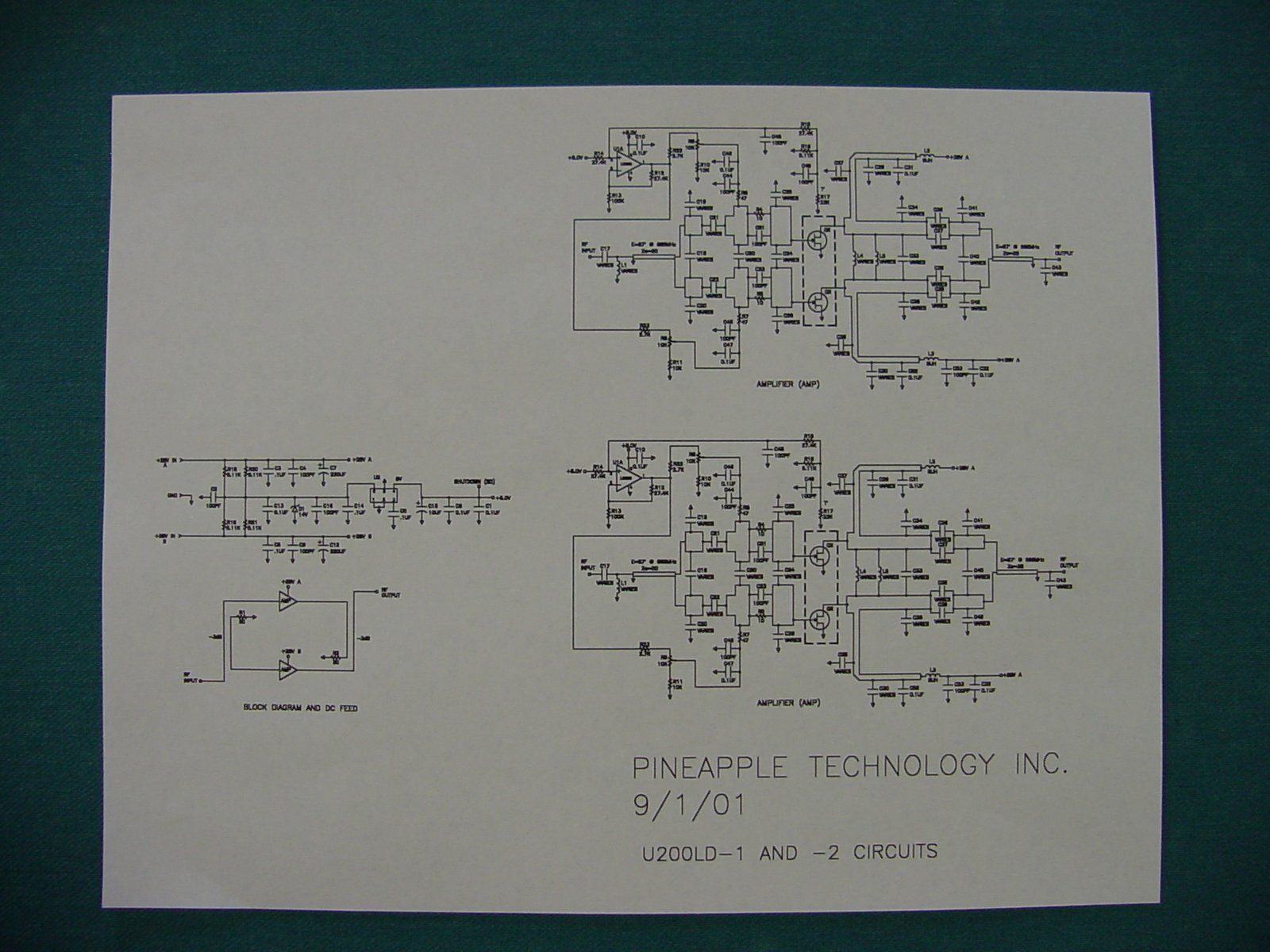
BLOCK DIAGRAM 45 MHz Combined Visual & Aural VHF to UHF Upconverter Bandpass Filter UHF Local Oscillator Low Voltage Power Supply RF Coupler Control & Power Metering Solid State 28 Vol t Pow e r Supply Solid state amplifier 100 wattVisual Items in dashed line comprise the UST106 Pro Retrofit kit.
Cover Letter(s)
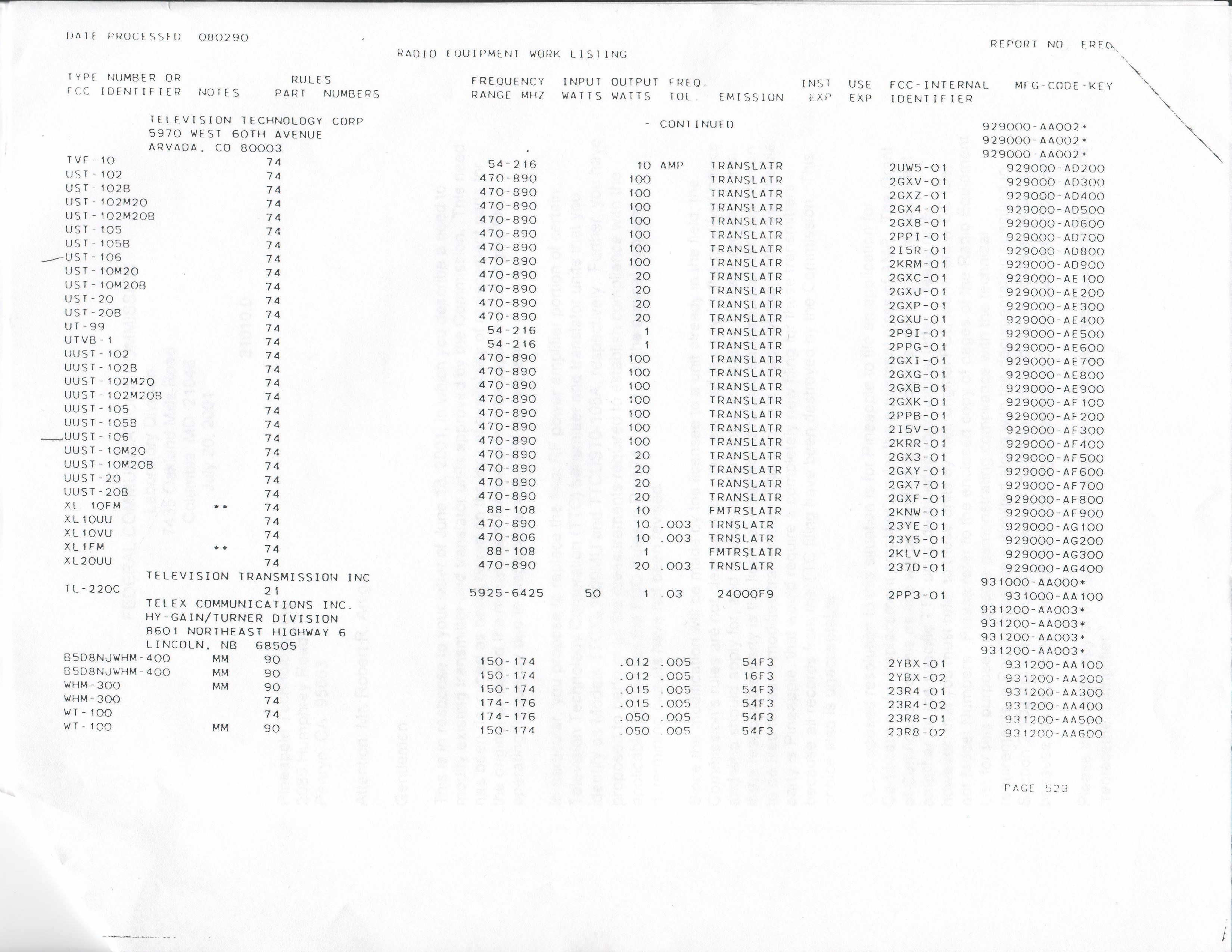
INTRODUCTION PINEAPPLE TECHNOLOGY APPLICATION FOR RETROFIT KIT FOR UST- 106A WITH RESPECT TO COMPLIANCE FOR PART 74. Pineapple Technology Inc. (PTI) has designed, built, tested and intends to market a retrofit kit, designated UST106 Pro, to retrofit Television Technology Corp. UST-106A TV translators with external modulator inputs. The kit consists of basically a wideband solid state power amplifier, RF bandpass filter, and power supply. The substitution of the solid state amplifier and power supply to replace existing tube amplifier in the UST-106A is accomplished with the attached modification instructions. The attached exhibit concerning the documentation of the retrofit kit is a preliminary version of the documentation. A final documentation package will be submitted upon its completion from the publisher. Confidentiality is requested for the portion of the documentation package that includes the schematics (including block diagrams) and wiring diagrams. The submission of the following exhibits is expected to demonstrate compliance with applicable Part 74 rules and regulations. As PTI has been in discussion with the FCC with regard to this retrofit kit, attached letter indicating the detailed requirements for filing with the FCC is also attached. FEDERAL COMMUNICATIONS COMMISSION Laboratory Division 7435 Oakland Mills Road Columbia, MD 21046 July 20, 2001 31010.0 Pineapple Technology, Inc. 2085 Humphrey Road Penryn, CA 95663 Attentio n: Mr. Robert R. Artigo Gentlemen: This is in response to your letter of June 13, 2001, in which you describe a need to modify existing transmitter and translator units approved by the Commission. This need has been described as being based o n the lack of availability of replacement parts for the original units and the requirement for the units to be capable of changing the operating frequency due to displacement by DTV assignments. In particular, yo u propose to replace the final RF power amplifier portion of certain Television Technology Corporation (TTC) transmitter and translator units that you identify as Models TTCXL1000MU and TTCUST0-106A, respectively. Further, you have proposed to perform all the measurements required to establish compliance with the applicable portions of the FCC Rules in Part 74, noting that the original frequency determining circuits have not been revised. Since the modification will be made by the licensee to a unit already in the field, the Commission’s rules are not clear o n who is the responsible party for the modified device and who should apply for, and receive, equipment authorizatio n of these modifications. If the responsible party is the licensee, that would require an application for Certification to be filed for each modified transmitter. This choice is unacceptable. If the respo nsible party is Pineapple, that would require a completely new filing for these transmitters because all records from the TTC filing have been destroyed by the Commission. This choice also is unacceptable. Our proposed resolution to this situation is for Pineapple to file an application for Certification of a “replacement amplifier” under the equipment class of AMP. The Grant of Certification for this device will be conditioned to apply the use of your “replacement amplifier” to the specific TTC units identified in yo ur original letter. Please note, however, that yo u must refer to these units by their original FCC identifiers (FCC IDs), not Model Numbers. Please refer to the enclosed copy of pages of the Radio Equipment List for this purpose. Test data demonstrating compliance with the technical requirements in Part 74 must be submitted along with the documentatio n specified in Section 2.1033(c) of the Rules. However, no frequency stability test data is required because, as you noted, none of the frequency determining circuitry has been modified. Please include a copy of this letter in yo ur application for equipment authorization of the “replacement amplifier.” I trust that this solution will allow the upgrade of the units that yo u desire. However, if you have any additional questions abo ut this matter, please contact Mr. Frank Coperich at the address above or by telepho ne at 301-362-3023. Sincerely, Richa rd Fabi na Chief Equipment Authorization Branch
Cover Letter(s)
January 4, 2002 Dear Sir: The applicant for this application does not wish to obtain confidentiality for any portion of the filing. Please remove this request from the application and proceed with the rest of the application. Sincerely, Greg Best Greg Best Pr esident Greg Best Consulting, Inc. 5541 Vantage Vista Drive Colorado Springs, CO 80919 719-592-9781
Cover Letter(s)
January 26, 2002 Office of Equipment Authorization Federal Communication Commission To Whom It May Concern: This letter w ill address the specific equipment this retrofit kit is designed to upgrade. The FCC identifiers associated w ith the TTC equipment models are the following: UST-106 UUST-106 Sincerely, Greg Best Greg Best Pr esident Greg Best Consulting, Inc. 5541 Vantage Vista Drive Colorado Springs, CO 80919 719-592-9781
Cover Letter(s)
January 26, 2002 Office of Equipment Authorization Federal Communication Commission To Whom It May Concern: This letter w ill address the request for the emission designator and other aural data for the FCC ID PW2U106T-PRO application. Please add this information to the appropriate places on the 731 form. The frequency range of operation is 470-806 MHz. The pow er level range is from 3 watts to 11 w atts. The emission designator that applies to the aural part of this equipment is 250kF3E. Since this equipment upgrades translator equipment, no frequency tolerance information is required as documented in the letter elsew here in the application by Richard Fabina of the FCC. Sincerely, Gregory L. Best Gregory L. Best Pr esident Greg Best Consulting, Inc. 5541 Vantage Vista Drive Colorado Springs, CO 80919 719-592-9781
Cover Letter(s)
January 26, 2002 Office of Equipment Authorization Federal Communication Commission To Whom It May Concern: This letter w ill address the specific equipment this retrofit kit is designed to upgrade. The FCC identifiers and aural emission associated with the TTC equipment models are the following: FCC IDMODEL NUMBEREmission designator Frequency RangePow er Output UST-106UST-106,UST-106ATranslator470-890 MHz100 UUST-106UUST-106,UUST-106ATranslator470-890 MHz100 Sincerely, Gregory L. Best Gregory L. Best Pr esident Greg Best Consulting, Inc. 5541 Vantage Vista Drive Colorado Springs, CO 80919 719-592-9781
External Photos
UST 106 PRO CONSTRUCTION PHOTOGRAPHS Cabinet Front View with door on. Rear view of Cabinet with back door on. Front View of Cabinet with front door off. Top portion of unit is displayed.
External Photos
Front View of Cabinet with front door off. Middle portion of unit is displayed. Front View of Cabinet with front door off. Lower portion of unit is displayed. Front View of Cabinet with front door off. Bottom portion of unit is displayed. Rear View of Cabinet with door open. Top portion of unit is displayed. Rear View of Cabinet with door open. Middle portion of unit is displayed.
External Photos
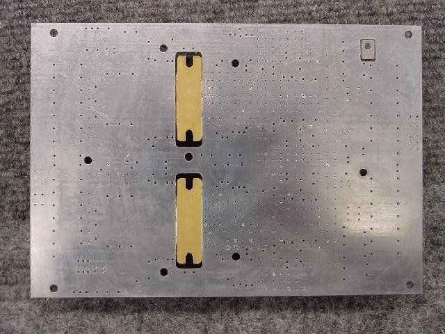
Rear View of Cabinet with door open. Bottom portion of unit is displayed. Solid State Power Amplifier Construction FCC LABEL TO BE USED ON THE UST 106 PRO
ID Label/Location Info
PINEAPPLE TECHNOLOGY, INC. FCC ID_________________________TRANSMITTER ID_________________MODEL_________________________S/N_________________________ Penryn, CA 95663 XL1000-PROPW2 PINEAPPLE TECHNOLOGY, INC. FCC ID_________________________TRANSMITTER ID_________________MODEL_________________________S/N_________________________ Penryn, CA 95663 U106T-PROPW2
ID Label/Location Info
PINEAPPLE TECHNOLOGY, INC. FCC ID_________________________TRANSMITTER ID_________________MODEL_________________________S/N_________________________ Penryn, CA 95663 U106T-PROFCC ID PW2U106T-PRO
ID Label/Location Info
PINEAPPLE TECHNOLOGY, INC. FCC ID_________________________TRANSMITTER ID_________________MODEL_________________________S/N_________________________ Penryn, CA 95663 U106T-PROPW2U106T-PRO
Operational Description
UST 106 PRO RETROFIT KIT THEORY OF OPERATION Introduction The UST 106 Pro is comprised of a solid state RF amplifier, Power supply, RF Filter to reduce spurious products and harmonics, and hardware kit to assemble the entire unit. The purpose of the kit is to replace the tube and cavity assembly that was part of the original equipment. System Operation The UST 106 Pro is designed to easily replace the existing tube amplifier and cavity assembly from a physical and operational point of view. The solid state power amplifier accepts the combined visual and aural on- channel RF signal from the upconverter at approximately 200 mW and amplifies the signal to the 100 watt rated visual power level and 10 watt aural power level. The RF filter accepts the on channel signal produced by the solid state amplifier and reduces the level of any out of channel intermodulation, harmonic, or spurious signals as viewed at the output ensuring compliance with all FCC regulations. The power supply converts the AC line voltage to a filtered DC voltage that is held constant independent of modulated RF waveform type and overall load. The power output control of the system continues to operate in the normal method as before the replacement of the tube and cavity system. Cooling is provided by an integral fan that is part of the amplifier module itself so no additional cooling is required. Solid State Power Amplifier The solid state amplifier consists of 2 stages of amplification using LDMOS technology. The amplifier is placed into operation by a circuit breaker switch located on the outside of the unit. The signal from the upconverter is applied to the driver stage. The class A driver stage serves as a low distortion linear amplifier that increase the combined visual and aural signal roughly 13 dB. This signal is routed to the parallel configured final amplifiers. The signal is split equally between 2 amplifiers and recombined to produce 100 watts of visual peak power and 10 watts of average aural power. The driver and final amplifier transistors receive 28 volts DC from the power supply. VSWR protection is provided in order that the transistors are not damaged from high reflected power operating conditions. An integral AC fan provides direct cooling air to the heatsink to ensure that the heat is removed efficiently from the PA module. The fan should be periodically cleaned to ensure reliable operation. The air filter on the fan should be examined and cleaned as necessary. The heatsink temperature is monitored and whenever it exceeds 64 degrees C, the front panel LED indicator is illuminated and the module shuts off. When the temperature decreases back to 53 degrees or less, the module automatically re-enables to the On state. Because the PA unit is broadband, it requires no tuning or adjustments. Two amplifiers are used to cover the entire UHF TV band. Power Supply The power supply architecture is a 28 volt DC power supply. The unit accepts a 110 or 220 volt 50/60 Hz source and is determined by a switch available from the outside of the unit. The output voltage is tightly regulated in order to eliminate any amplitude modulation on the output RF signal. Current limit protection is built in to the power supply should it accidentally encounter a very high current demand. The output voltage range is adjustable from 26 to 29 volts and is set by an adjustment located on the rear panel of the power supply. The power supply is cooled by an internal fan. Power connections are made between the power supply and the power amplifier unit by mating plug connectors. RF Filter The RF filter is an 8 section bandpass filter designed to pass signals in the designated channel and reject all others. Connections for the RF input and output are made through 50 ohm Type N connectors. The number of sections of the filter does not permit field tuning of the filter without the use of a tracking generator and spectrum analyzer or network analyzer. The filter has approximately 1.0 dB insertion loss in the desired channel.
Parts List/Tune Up Info
UST-106A PRO PARTS LIST PART NUMBERQUANTITYDESCRIPTION MF91721BRACKET, TYPE N FEEDTHRU MF91731BRACKET WITH CUTOUT MF91741MRG BRACKET FOR FILTER MTG AC20031AC POWER SUPPLY U106T1UHF PA ASSEMBLY BPF100-U81BANDPASS FILTER 8 POLE AC61011AC POWER CORD CA54111COAX CABLE RG141 CA54121COAX CABLE RG141 CA52111DC CABLE ASSEMBLY CA52131GROUND STRAP
Test Report
TEST REPORT PINEAPPLE TECHNOLOGY INC. 106A RETROFIT KIT TECHNICAL REPORT INTRODUCTION The following information is provided to support the technical performance of the UST106 Pro Retrofit Kit for the Television Technology TV translator designated as the UST-106A (modulator input version). The information is supplied for broadcast TV service according to applicable portions of Part 74 and the attached letter from the FCC OET office. The following information is provided in support of acceptance of the retrofitted transmitter for Part 74 service. Where possible, measurements were recorded of spectrum or other appropriate data of the signal in the RF path before and after the retrofit amplifier. 1. Power Output Measurements as indicated by FCC Rule Part 2.1046. 2. Visual Frequency response measurements of the translator to be within window specified by FCC Rule Part 74.750. 3. Occupied BW of aural signal specified by FCC Rule Part 2.1079. 4. Measurement of conducted harmonics and spurs +/- 3 MHz outside of channel as specified by FCC Rule Part 74.750. 5. Measurement of cabinet radiation of spurs and harmonics as specified in FCC Rule 2.1053 and 2.1057. 6. Measurements of voltage and current to final amp stage as outlined in FCC Rule 2.1033. Measurements of frequency response, harmonics, and spurs have been executed and compared to the same measurements before the amplifier. The purpose of providing both sets of measurements is to indicate that the substitution of the PTI solid state amplifier did not degrade the performance of the translator and allows the translator to comply with the applicable rules and regulations of Part 74. Measurements were conducted at power output levels of 30 watts peak of sync and 110 watts peak of sync and constitute the range of power for which type certification is sought. As indicated in the attached documentation from the FCC in another exhibit, the other parameters normally associated with Part 74 service such as frequency stability and receiver dynamic range do not apply to this application for certification. The complete test report is divided into 5 subsections including this one labeled Test Report #1 thru #5 to put the data into manageable file sizes. The test equipment used for the measurements on the next few pages is listed at the end of the last report (Test Report #5 file). All test equipment had been calibrated prior to the use of the equipment by the supplier of the test equipment. RF Power Output The equipment was configured as below shown in Figure 1. The loss through the RF output cable and directional coupler and attenuator was calibrated at the Visual carrier frequency of 537.25 MHz. The NTSC generator was configured to produce a signal with 0 IRE video and sync. The audio generator was not energized. Visual peak power was read on the HP8900C Peak Power Meter and a reference level was established on the HP8595E Spectrum Analyzer. The TV demodulator was used to verify that sync compression was not causing any distortion of the measurement. The aural output level was then raised to meet the precise 10 dB Visual/aural power ratio as observed on the spectrum analyzer photograph. Pictures were also taken of demodulated video of the horizontal sync, and 2 fields of video to verify no signal distortions were present over the 30 watt to 110 watt power level range that certification is being sought. Please see Figure 1 and remaining photographs in this test report and Test Report #2 file. Dashed lines indicate connection to 1 of the 3 pieces of equipment. Power Output 36 mWatts peak indicated +34.8 dB (loss due to directional coupler, attenuator and cable) = 110 watts peak of sync power CH A NTSC Gen Wavefor m mo nitor Mod ulator Translator under test Spectrum Analyzer Audio Gen Load TV Demod HP wattme ter Dir. Coupler CH B Figure 1 POWER OUTPUT ON SPECTRUM ANALYZER Horiz. Sync (OUTPUT @110 watts) Horiz. Sync (OUTPUT @30 watts)
Test Report
Horizontal Sync (Input to amp)2 Fields (Input to amp) 2 Fields (Output @ 110 watts) 2 Fields (Output @ 30 watts)
Test Report
Frequency Response Frequency Response characteristics were measured using the equipment shown in Figure 1 (see Test Report #1). A (sinX)/X waveform was used to generate a flat frequency response spectrum. The aural carrier was reduced as much as practical to be able to observe the spectrum but it could not be eliminated. Measurements were recorded at a place before the retrofit amplifier and after the retrofit amplifier at 30 watts and 110 watts output power. Data is displayed with a 5 dB/division scale. The data indicates the frequency responses are essentially identical. Thus the amplifier does not degrade the frequency response signal applied to the original translator. Measurements indicate the amplifier output response is within the 4 dB window as specified by FCC Rule 74.750. Output Frequency Response @ 110 watts peak (5 dB/div) Frequency Response (5 dB/div) (Input) Output Frequency Response @ 30 watts peak (5 dB/div)
Test Report
Occupied Bandwidth The equipment was configured as in Figure 1 (Test Report #1). The aural signal was increased in power level to the appropriate 10 dB ratio. An audio signal generator was connected to the modulator audio input and the frequency was adjusted to 10.396 kHz and the audio level was increased to obtain a Bessel null at the carrier frequency to ensure deviation was correctly adjusted. The modulating frequency was changed to 15 kHz and the modulation was reduced to 85% and the spectrums were recorded at the output of the translator. Output at 110 wattsOutput at 30 watts All spectral components outside the 200kHz BW constitute less than .5% of the total power and thus comply with FCC regulations
Test Report
Conducted Harmonic and spurious signals The equipment was configured as shown in the Figure 1 (Test Report #1.) The translator was operated at 110% visual power with a 10 dB visual/aural ratio. Measurements were recorded in the RF chain both before and after the retrofit amplifier. The top left photo below is the signal applied to the amplifier input indicating spurious signals just outside the channel. The top right photo below indicates the harmonics present at the input of the retrofit amplifier. The top of the spectrum analyzer screen is the level of the fundamental signal (i.e. harmonics are –40 dB on the input). The figures in the near the bottom on this page indicate that the spurious components outside the channel and harmonics meet the requirement at 30 watts output as outlined in FCC Rule 74.751(c). Harmonics and spurious levels at 110 watts peak power are shown in the following test report (See Test Report #5.) Adjacent channel spurious (input) 2 nd Harmonic area spectrum (input) Adjacent channel spurious 2 nd Harmonic area spectrum Output @ 30 watts peak Output @ 30 watts peak
Test Report
Adjacent channel spurious2 nd Harmonic area spectrum Output @ 110 watts peak Output @ 110 watts peak The photos shown above are harmonic and spurious measured at the translator output for power levels of 110 watts peak. The only spectral components other than the spurs indicated in the left photo are harmonics of the visual and aural carriers. A photo showing the harmonics at the 2 nd harmonic frequencies is shown on the right. The cable and directional coupler were calibrated for loss at each spurious and harmonic frequency identified. All other harmonic and spurious levels are >80 dB below rated output power. The harmonic and spurious levels are recorded in the table below. Output Power = 110 watts peak sync Spectral FrequencyDisplayed ValueCorrected value* 546.25 MHz (Fv + 9)-70 dB-80 dB 532.75 MHz (Fv - 4.5)-53 dB-63 dB 1.074 GHz (Fv x 2)-63 dB-67 dB 1.084 GHz (Fa x 2)-65 dB-69 dB *Corrected for cable loss and coupling factor from the test setup and notch filters at visual and aural carriers. Cabinet Radiation The translator and test equipment was configured as shown on the following page. The photo on the next page also shows the physical set- up of the test equipment and equipment under test. The translator was operated at 110% power with a 10 dB visual/aural ratio with the video input signal being a sync signal and 0 IRE “set-up” level. The free space path loss, cable loss, and antenna gain characteristics were obtained at the fundamental frequency at each of the harmonics of the visual carrier frequency in order to accurately assess the level of the signal radiated from the cabinet. The cabinet was measured in 4 different physical rotation angles: 0, 90, 180, and 270 degrees (0 degrees being the front of the cabinet). All spectral components above -80 dB referenced to peak sync power radiated from the cabinet were recorded. Their values are tabulated in the following table. Output Power = 110 watts peak sync Spectral FrequencyDisplayed ValueCorrected value* 546.25 MHz (Fv + 9)-72 dBm-75.6 dB 532.75 MHz (Fv - 4.5)-68 dBm-71.6 dB 1.074 GHz (Fv x 2)-66 dBm-63.4 dB 1.084 GHz (Fa x 2)-67 dBm-64.4 dB 1.07 GHz-71 dBm-68.4 dB 1.079 GHz-67 dBm-64.4 dB *Corrected for cable loss, antenna gain, path loss and notch filters at visual and aural carriers and compared to Peak Sync power. Notch Filter Receiving Antenna NTSC Gen Wavefor m mo nitor Mod ulator Translator under test Spectrum Analyzer Load Front Figure showing Test setup for cabinet radiation. Cabinet was rotated to measure radiation from four angles. Foreground shows receiving antenna, notch filters, and spectrum analyzer. Worst case measurement of cabinet radiation measured at 2 nd harmonic of visual carrier. Final Amplifier Voltage and Current Measurements Final amplifier voltage and current measurements were made with the translator operating at 110% power and at 30% power. A video input signal of sync and 0 IRE “setup” level was used. Voltage measurements were made usi…
Text truncated - open the document above for the full version.
Contact Information
Applicant
Robert Artigo(President)
Technical Contact
Greg Best Consulting, Inc.Gregory L Best
[email protected]719-592-9781
5541 Vantage Vista Drive · Colorado Springs, Colorado · United States
Technical Specifications
| # | Rule Parts | Frequency Range | Power Output | Emission | Tolerance |
|---|---|---|---|---|---|
| 2 | 74 | 470 MHz - 806 MHz | 11 W | 250KF3E | 0.005 % |
Other Applications from Pineapple Technology, Inc.

PW2DTXPRO10U
Aug 31, 201110 W DTV TRANSMITTER
Equipment Class
TBC - Licensed Broadcast Station Transmitter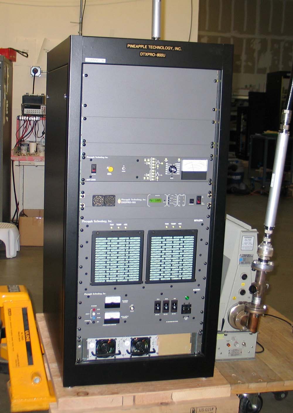
PW2DTXPRO800U
Mar 01, 2011800 W DTV TRANSMITTER
Equipment Class
TBC - Licensed Broadcast Station Transmitter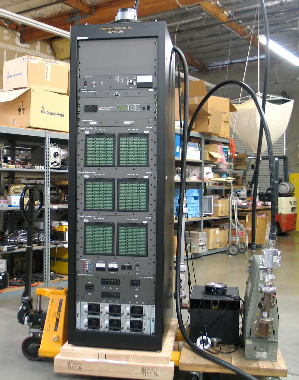
PW2DTXPRO2300U
Mar 01, 20112.3KW DTV TRANSMITTER
Equipment Class
TBC - Licensed Broadcast Station Transmitter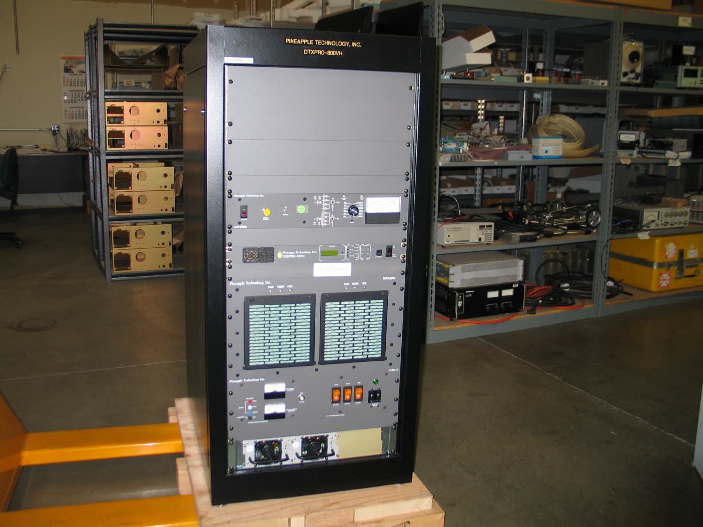
PW2DTXPRO800VH
Feb 27, 2011800 WATT DTV TRANSMITTER
Equipment Class
TBC - Licensed Broadcast Station Transmitter
PW2DTXPRO1200U
Dec 12, 20101.2 KW DTV TRANSMITTER
Equipment Class
TBC - Licensed Broadcast Station Transmitter