PW2UTX1KW1.0 KW Television Transmitter
Pineapple Technology, Inc.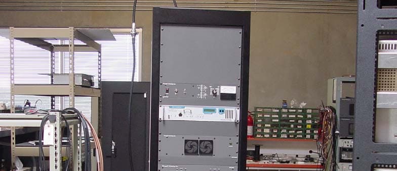
Click to zoom
Application Details
- Equipment Class
- TBC - Licensed Broadcast Station Transmitter
- Date of Grant
- Oct 04, 2004
- Application Purpose
- Original Equipment
- Date of Application
- Aug 11, 2004
- Equipment Note
- 1.0 KW Television Transmitter
- Frequency Range
- 470.00000000 - 801.00000000
- Company
- Pineapple Technology, Inc.
- Country
- United States
Documents & Files

Document Text
Text extracted from the exhibit documents filed with the FCC. Open a document above to read the original.
Users Manual
U T X 1 K W - A INSTRUCTION MANUAL SN: PINEAPPLE TECHNOLOGY, INC. PINEAPPLE TECHNOLOGY, INC. UTX1KW-A Operating and Service Manual TABLE OF CONTENTS Section I — SAFETY NOTICES.................................................................................................2 **READ THIS SECTION BEFORE INSTALLATION** Section II — UTX1KW-A TRANSMITTER SPECIFICATIONS......................................3 Section III — TRANSMITTER INSTALLATION...................................................................5 Section IV — TRANSMITTER TURN-ON...............................................................................6 Section V — THEORY OF OPERATION A. Introduction ............................................................................................................................8 B. ACDIS1 ................................................................................................................................10 C. RR6000 Power Supply .........................................................................................................10 D. ADP1000 Performance Monitor ..........................................................................................10 E. Remote Monitor and Control W/ABS ..................................................................................12 F. Modulator/Driver..................................................................................................................12 G. DRV100DC-1 Driver............................................................................................................12 H. US200 Splitter ......................................................................................................................12 I. MFA1KW Power Combiner.................................................................................................13 J. U600LDV2 Power Amplifi er................................................................................................13 K. UC1KW Power Combiner....................................................................................................13 L. DC40-1KW Dual Directional Coupler.................................................................................14 M. BPU1KW UHF.....................................................................................................................14 Section VI — SCHEMATIC AND PARTS LISTS A. UTX1KW-A .........................................................................................................................15 B. ACDIS1 ................................................................................................................................16 C. DRV100DC-1 .......................................................................................................................19 D. MFA1KW .............................................................................................................................21 1. 1A0035 Status Board.......................................................................................................23 E. U600LDV2 ...........................................................................................................................25 1. U250LD...........................................................................................................................28 2. 1A0025 Power Distribution Monitor...............................................................................32 3. 1A0018 Gain and Phase Matching ..................................................................................35 F. SPLITTER US200................................................................................................................37 G. COMBINER UC1KW..........................................................................................................38 H. ADP1000 Monitor ................................................................................................................39 1. 1A0027 ............................................................................................................................44 2. 1A0029 ............................................................................................................................46 3. 1A0030 ............................................................................................................................49 Section VII — RECOMMENDED ROUTINE MAINTENANCE......................................50 Section VIII — ADJUSTMENTS AND TUNING................................................................51 Section IX — PROBLEM SOLVING / TROUBLE SHOOTING......................................53 Section X — WARRANTY...........................................................................................................55 Section XI — EXTENDED WARRANTY................................................................................56 Page 1 PINEAPPLE TECHNOLOGY, INC. UTX1KW-A Operating and Service Manual I — SAFETY NOTICES I — SAFETY NOTICES **READ THIS SECTION BEFORE INSTALLATION** SEVERE ELECTRICAL SHOCK OR BURNS MAY OCCUR IF THIS EQUIPMENT IS USED IMPROPERLY. ~~~~~~~~~~~~~~~~~~~~~~~~~~~~~~~~~~~~~~ NEVER WORK ON THIS EQUIPMENT ALONE. ALWAYS HAVE ANOTHER PERSON PRESENT WHILE WORKING ON ELECTRICAL CIRCUITS OR MOVING EQUIPMENT. COMMUNICATIONS TO EMERGENCY SERVICES SHOULD BE AVAILABLE AT ALL TIMES. ~~~~~~~~~~~~~~~~~~~~~~~~~~~~~~~~~~~~~~ BEFORE CONNECTING THIS EQUIPMENT TO ANY AC ELECTRICAL SOURCE READ THE SECTION ON INSTALLATION. ALL ELECTRICAL WIRING FOR THIS EQUIPMENT MUST BE PERFORMED BY QUALIFIED ELECTRICIANS. ALL WIRING MUST BE COMPLIANT WITH LOCAL ELECTRICAL CODES. ~~~~~~~~~~~~~~~~~~~~~~~~~~~~~~~~~~~~~~ POWER AMPLIFIERS AND SUPPLIES ARE HEAVY. TO INSTALL THIS EQUIPMENT IN RACKS, USE TWO (2) PERSONS TO AVOID POSSIBLE INJURIES. ~~~~~~~~~~~~~~~~~~~~~~~~~~~~~~~~~~~~~~ NEVER OPEN THE CABINET ENCLOSURE OR UNPLUG CABLES OR WIRES WHILE THIS EQUIPMENT IS OPERATING. ~~~~~~~~~~~~~~~~~~~~~~~~~~~~~~~~~~~~~~ ALL SERVICE…
Text truncated - open the document above for the full version.
Attestation Statements
August 12, 2004 FCC Office of Equipment Authorization To Whom It May Concern: ATTESTATION STATEMENT I hereby certify the measurements and test results were made and recorded in accordance with accepted engineering practices and do constitute an accurate representation of the product performance of the documented UTX1KW TV transmitter serial number 001. Signed, Gregory L. Best President, Greg Best Consulting, Inc. GREG BEST CONSULTING, INC. 5541 Vantage Vista Drive Colorado Springs, CO 80919 719-592-9781
Block Diagram
BLOCK DIAGRAM UTX1KW TV TRANSMITTER UHF Exciter RF Combiner Bandpass Filter & Coupler Control & Power Metering Circuits Solid State Power Supply ( X2 ) Solid State Driver 1000 watt Visual 100 watt Aural RF Splitter Solid State Power A mplifiers AC Voltage Distribution Cabinet fan Assembly Video Audio
Cover Letter(s)
1 August 12, 2004 FEDERAL COMMUNICATIONS COMMISSION MEDIA BUREAU—VIDEO DIVISION 445 12 ST. SW WASHINGTON, DC 20554 PINEAPPLE TECHNOLOGY INCORPORATED APPLICATION FOR UTX1KW TV TRANSMITTER TYPE CERTIFICATION Pineapple Technology Inc. (PTI) has designed, built, tested and intends to market a Television transmitter with model UTX1KW. Type certification is sought over the range of 100 watts to 1.0 kW visual output power. This transmitter is a common amplification system with 10% aural power. The attached documentation of the user manual is a preliminary version of the documentation. A final documentation package will be submitted upon its completion from the publisher. The submission of the following exhibits is expected to demonstrate compliance with applicable Part 2, Part 73, and Part 74 rules and regulations. Sincerely, Greg Best President Greg Best Consulting, Inc. 9223 N. Manning Ave. Kansas City, MO 64157 816-792-2913
External Photos
UTX1KW EXTERNAL CONSTRUCTION PHOTOGRAPHS FRONT VIEW TOP FRONT BOTTOM FRONT
External Photos
UTX1KW EXTERNAL CONSTRUCTION PHOTOS (CONT.) LEFT SIDE RIGHT SIDE REAR VIEW
Internal Photos
UTX1KW INTERNAL CONSTRUCTION PHOTOGRAPHS REAR VIEW UTX3KW UPPER REAR UTX3KW MIDDLE REAR UTX3KW LOWER REAR
Operational Description
UTX1KW THEORY OF OPERATION Introduction The UTX1KW Television Transmitter is a TV transmitter capable of providing 1 kW of visual RF power and 100 watts of aural power at the output of the transmitter. The transmitter is comprised of a precision modulator and upconverter, driver amplifier, 2 way power splitter, 2 solid state RF power amplifiers operating in parallel, a 2 way power combiner, 2 DC power supplies, RF filter to eliminate spurious products and harmonics, cooling system, AC voltage distribution system, control and monitoring system for the human interface, and all necessary hardware to assemble the transmitter into the transmission facility. The transmitter system is housed in one 19 inch rack. System Operation RF SIGNAL GENERATION Video and audio are fed to the high quality TV modulator/upconverter where the high quality TV visual and aural signals are produced. The upconverter converts the modulated TV signal to its desired channel and eliminates the image frequency product. The solid state driver amplifier accepts the combined visual and aural on-channel RF signal from the upconverter and amplifies the signal with minimum distortion. The signal is fed to a 2 way splitter that distributes an in-phase and equal amplitude signal to each of the power amplifiers. Each power amplifier accepts the RF signal and is capable of producing a 600 watt peak of sync NTSC TV waveform. The 2 way combiner accepts the power amplifier RF signals and combines the signals to one common output connector. The output signal from the combiner feeds a directional coupler. The output signal from the directional coupler passes through a bandpass filter that reduces all out of channel intermodulation products and harmonics to an acceptable level consistent with FCC rules. POWER SUPPLY SYSTEM The incoming single phase AC power passes through a circuit breaker control panel that distributes the power to various assemblies throughout the transmitter. From the circuit breaker panel, separate AC lines are fed to the modulator/upconverter, driver, control and monitoring system, and air cooling system, as well as auxiliary outlets for the transmitter. The UTX1KW utilizes 2 DC power supplies. Input AC voltage is fed to each of the DC power supplies via one power supply frame designed to house all of the power supplies. Each one of the DC power supplies converts the AC line voltage to approximately 31 volts DC. Its voltage is held constant independent of modulated RF waveform type and overall load. DC outputs from the power supplies are connected in parallel. The power supplies share the load current required by the amplifier group. The parallel connection and smart circuitry of the power supplies allows the power supplies to share the load. SOLID STATE POWER AMPLIFIER Each solid state power amplifier (PA) consists of 2 stages of amplification using LDMOS technology. The power gain of each power amplifier is approximately 26 dB. Within each power amplifier, the first stage serves as a low distortion linear amplifier that increases the power of the combined visual and aural signal roughly 13 dB. This output signal is routed to 4 parallel configured final amplifiers. The driver and final amplifier transistors receive DC voltage from the power supply frame elsewhere in the rack via connections on the rear of the amplifier. VSWR and over-temperature protection is provided in order that the transistors are not damaged from high reflected power operating conditions. The heatsink temperature is monitored and whenever it exceeds a pre- determined temperature, a front panel LED indicator is illuminated and the power amplifier module shuts off. Integral fans provide direct cooling air to the amplifier heatsinks to ensure that the heat is removed efficiently from the PA modules. When the temperature decreases back below the threshold, the power amplifier automatically re-enables to the “On” state. Because the PA unit is broadband, it requires no tuning or adjustments. POWER SUPPLY The power supply architecture is a very efficient DC switching power supply unit. Each power supply is hot-pluggable and is inserted and removed from the front of the transmitter. The unit accepts voltage from a 50 or 60 Hz source. The output voltage is tightly regulated in order to eliminate any amplitude modulation on the output RF signal. Current limit protection is built in to the power supply should it accidentally encounter a very high current demand. Each power supply is cooled by internal fans. RF SPLITTER AND COMBINER The RF splitter is an assembly that separates the RF signal into equal amplitude and in-phase signals for each port. The RF combiner reverses the process and combines the amplifier outputs together. Each group of input cable, power amplifier, and output cable is matched for the same transmission phase angle and amplitude to be present at the RF combiner input RF FILTER The RF filter is a multiple section bandpass filter designed to pass signals in the designated channel and reject all others. Connections for the RF input and output are made through 50 ohm connectors. The filter is tuned to a specific TV channel. CONTROL AND MONITORING SYSTEM The control and monitoring system of the transmitter provides the following functions: Forward Visual, forward Aural, and combined reflected power output level monitoring Status lights for the power amplifier modules Metering for all power amplifier currents RF sample port for monitoring the forward signal using separate test equipment Power Amplifier enable/disable switch AIR COOLING SYSTEM An exhaust fan on the top of the cabinet provides cooling for the system. Cool air is drawn through the front of the transmitter by highly reliable fans in the individual amplifier modules and exhausted at the back of the amplifiers. The exhaust fan pulls the warm air from the amplifiers up to the top of the cabinet.
Parts List/Tune Up Info
September 15, 2004 Federal Communications Commission OET Equipment Authorization Branch Washington DC Dear Sir, This letter is to inform you that the parts list/tune up info for the UTX-1KW TV transmitter is contained in the user manual which has already been uploaded to the OET website. Sincerely, Greg Best President Greg Best Consulting, Inc. 9223 N. Manning Ave. Kansas City, MO 64157 816-792-2913
RF Exposure Info
RF EXPOSURE INFORMATION This equipment does not exceed the applicable radiated RF limits identified for Part 73 or Part 74 TV transmission equipment. Measurements are supplied regarding radiation from the transmitter cabinet. Please see Test Report for test results.
Schematics
September 15, 2004 Federal Communications Commission OET Equipment Authorization Branch Washington DC Dear Sir, This letter is to inform you that the schematics for the UTX-1KW TV transmitter are contained in the user manual which has already been uploaded to the OET website. Sincerely, Greg Best President Greg Best Consulting, Inc. 9223 N. Manning Ave. Kansas City, MO 64157 816-792-2913
Test Report
TEST REPORT PINEAPPLE TECHNOLOGY INC. UTX1KW TV TRANSMITTER TECHNICAL REPORT INTRODUCTION The following information is provided to support the technical performance of the Pineapple Technology UTX1KW TV Transmitter. The information is supplied for broadcast TV service according to applicable portions of Part 73 and 74. 1. Power Output Measurements as indicated by FCC Rule Part 2.1046. 2. Frequency Measurements as identified by FCC Rule Part 2.1055. 3. Visual Frequency response measurements of the transmitter to be within the window specified by FCC Rule Part 74.750. 4. Occupied BW of aural signal specified by FCC Rule Part 2.1079. 5. Aural frequency response as identified by FCC Rule Part 73.687 6. Measurement of conducted harmonics and spurs +/- 3 MHz outside of channel as specified by FCC Rule Part 74.750 and Part 2 Rule 2.1051. 7. Measurement of cabinet radiation of spurs and harmonics as specified in FCC Rule 2.1053 and 2.1057. 8. Measurements of voltage and current to final amp stage as outlined in FCC Rule 2.1033. Measurements were conducted at transmitter visual power output levels of 1000 watts peak of sync and 100 watts peak of sync and constitute the range of power for which type certification is sought. The corresponding aural power levels are 100 watts and 10 watts. Measurements were taken on a unit with visual carrier frequency of 549.25 MHz and an aural carrier frequency of 553.75 MHz. The test equipment used for the measurements on the next few pages is listed at the back of this exhibit. All test equipment was calibrated prior to the use of the equipment by the supplier of the test equipment. RF POWER OUTPUT The equipment was configured as below shown in Figure 1. The loss through the RF output cable, directional coupler and attenuator was calibrated at the frequency of 549 MHz. The TSG-90 video generator was configured to produce a signal with 0 IRE video and sync. The audio generator and aural carrier were not energized. The visual portion of the transmitter was energized and the power was increased to the desired output power. The power was read on the Bird wattmeter and a reference level was established on the HP8595E Spectrum Analyzer. The TV demodulator and VM-700 were used to verify that sync compression was not causing distortion of the measurement. The aural carrier was energized and its output level was then raised to meet the precise 10 dB Visual/aural power ratio as observed on the spectrum analyzer. Pictures were also taken of demodulated video of the horizontal sync, and 2 fields of video to verify no signal distortions were present over the 1.0 kwatt to 100 watt power level range where certification is being sought. POWER OUTPUT Bird Thruline reading Bird Thruline reading at high power= 600 watts at low power= 60 watts Peak of sync power = 1.68 times Peak of sync power = 1.68 times average power reading with a black average power reading with a black picture and “0” setup picture and “0” setup Peak of sync power = 600 x 1.68 Peak of sync power = 60 x 1.68 = 1008 watts = 101 watts Tektronix TSG-90 Video Generator Tektronix 1410 Video Generator HP 200CD Audio Oscillator Tektronix VM700T HP 54601 Oscilloscope UTX1KW Bird Load MSI TV Demodulator Agilent 8593E Spectrum A nal y zer HP 8903B Modulation A nal y zer TEST EQUIPMENT CONFIGURATION 40 dB coupler A udio Video Video Quadrature Video Dashed line indicates onl y one instrument connected at a time. Bird Wattmeter POWER OUTPUT ON SPECTRUM ANALYZER (showing 10 dB V/A Ratio) TWO HORIZONTAL LINES AND TWO FIELDS SHOWING CORRECT MODULATION DEPTH FOR REFERENCE WHITE AND SYNC LEVELS AT 1.0 KW Power Output = 1.00 kwatt Power Output = 1.0 kwatt
Test Report
TWO HORIZONTAL LINES AND TWO FIELDS SHOWING CORRECT MODULATION DEPTH FOR REFERENCE WHITE AND SYNC LEVELS AT 100 W Power Output = 100 watts Power Output = 100 watts FREQUENCY STABILITY MEASUREMENTS Frequency stability versus temperature and line voltage was measured in a controlled environment. For these tests, the exciter RF output was fed to a frequency counter that has better than a 1ppm accuracy. The test equipment configuration is shown below. The variac was adjusted for nominal voltage and the frequency was recorded. Then the variac was adjusted to 85% and 115% of the nominal voltage and the frequency was recorded at each voltage level. The results are tabulated below. LINE VOLTAGE (Volts) Visual Frequency (MHz) Aural Frequency (MHz) 100 (85%) 549.250045 553.750041 121 (nominal) 549.250046 553.750040 140 (115%) 549.250046 553.750040 For the temperature stability measurements the exciter was placed inside a Tenney temperature chamber equipped with a MicroTenn II temperature controller. The exciter frequency was measured on the frequency counter. The temperature in the chamber was changed to each of the points identified in the table below. The chamber followed a prescribed rate of 10 minutes to change the temperature and then the temperature was allowed to stabilize at the temperature for 10-15 minutes. When the temperature had stabilized, the exciter visual and aural frequencies were recorded, and then the temperature was advanced to the next measurement point. The temperature was cycled cold first and then returned to room temperature and then cycled hot. Temperature °C Time Visual Frequency (MHz) Aural Frequency (MHz) 25 9:20 am 531.250050 535.750056 20 9:35 am 531.250041 535.750046 10 10:25 am 531.250041 535.750050 0 10:45 am 531.250037 535.750046 -10 11:10 am 531.250032 535.750042 -20 11:55 am 531.250031 535.750039 -30 12:15 pm 531.250030 535.750038 25 12:40 pm 531.250038 535.750045 30 1:00 pm 531.250043 535.750050 40 1:25 pm 531.250049 535.750056 50 1:50 pm 531.250055 535.750062 The recorded data indicates that the frequency stability requirements of FCC Rule 2.1055 were met. Exciter Frequency Counter Variac AC Input AC OutputRF Output Exciter Frequency Counter Temperature Chamber RF Output
Test Report
VISUAL TRANSMITTER FREQUENCY RESPONSE MEASUREMENTS The test equipment configuration of Figure 1 was used with the 1410 video generator supplying the video input waveform. For this case, the aural carrier was not energized. A variable frequency sine wave of 90 IRE Peak-to-Peak amplitude from 200 kHz to 5.75 MHz with pedestal set at 52.5 IRE input video waveform was used. The modulation output was increased until the maximum excursion reached reference white and 10 IRE as shown in the photo below. The frequency of the variable sine wave was varied between 200 kHz to 5 MHz in 500 kHz steps. The RF sideband output level was measured for the sidebands below and above the visual carrier. The frequency response was plotted. The plots were scanned and are shown beginning on the next page. Spectrums for both 1.0 kW power and 100 W conditions are displayed to confirm that the radiated envelope meets the requirements as outline in Part 74 Rule 750. FREQUENCY RESPONSE INPUT WAVEFORM The sweep amplitude of 90 IRE establishes a spectrum component at -14 dB reference to peak of sync output power. The frequency response measurements are tabulated below for upper and lower sideband values at power levels of 1 kW and 100 W and plotted on the next page to demonstrate compliance with the frequency response Rule 74.750. The tabulated values are compared to the -14 dB reference in the tables but plotted on an absolute level. Power Level Pout = 1 kW Pout =100 W Frequency LSB USB LSB USB 200 kHz Ref Ref Ref Ref 500 kHz -2.0 -1.0 -0.7 +0.7 1.0 MHz -20 -0.8 -7.0 +1.2 1.5 MHz -22 -0.2 -26 +1.0 2.0 MHz -21 -1.0 -25 +1.0 2.5 MHz -31 -1.0 -26 +1.5 3.0 MHz -36 -1.0 -30 +1.2 3.5 MHz -36 -0.7 -37 -0.0 4.0 MHz -36 -2.0 -44 -0.0 4.5 MHz -36 -2.0 -45 -0.5 5.0 MHz -36 -3.0 -48 -.0.7 PLOT OF SPECTRUM AT POWER OUTPUT =1.0 kwatt PLOT OF SPECTRUM AT POWER OUTPUT =100 watts
Test Report
OCCUPIED BANDWIDTH MEASUREMENTS The test equipment was configured as in Figure 1. The aural carrier was energized and increased in power until the desired Visual to Aural power ratio of 10 dB was met. The visual input waveform used was a “0” IRE video input level from the TSG-90 and the aural input signal was a 15 kHz sine wave taken from the HP 200CD audio generator. The aural deviation was increased until the desired level (85% of 25 kHz = 21.25 kHz) was indicated on the HP8903B modulation analyzer and on the calibrated deviation output of the MSI 320 TV demodulator. The output spectrum was observed on the HP 8593 spectrum analyzer noting the requirements as identified in FCC Rule Part 2.1079. As can be observed, the output spectrum meets these requirements. OCCUPIED BANDWIDTH—POWER OUTPUT = 1.0 kWatt (Scan width = 200 kHz) OCCUPIED BANDWIDTH—POWER OUTPUT = 100 Watts (Scan width = 150 kHz)
Test Report
AURAL FREQUENCY RESPONSE The equipment configuration of Figure 1 was used. The visual and aural carriers were energized and the aural carrier was modulated by the HP200CD audio frequency generator. A reference level was set at 500 Hz and the audio generator level was adjusted to achieve 25 kHz deviation at each modulating frequency using the calibrated audio output (in mvolt/kHz) from the MSI 320 TV demodulator. An oscilloscope was used to compare the input voltage with the output demodulated voltage from the MSI 320 TV Demod to determine the response level. The following table of audio response was obtained by dividing the output audio level by the input level. This table is plotted on the graph shown below. The input termination to the UTX3KW was fixed at 600 ohms. FREQUENCY RESPONCE FREQUENCY (Hz)AMPLITUDE (dB) 50 -0.3 100 -0.2 200 -0.2 500 Reference 1000 0.7 2000 2.3 4000 6.2 8000 11.3 10000 13.4 13000 14.5 15000 15.0 AURAL FREQUENCY RESPONSE GRAPH WITH LIMITS The green line is the plotted results.
Test Report
CONDUCTED SPURIOUS AND HARMONICS The following photographs indicate the spurious performance (> +/- 3 MHz) from the designated TV channel. As can be seen from the photos (one taken at 1.0 kW and the other taken at 100 W), the worst case spurious levels are below 64 dB relative to the peak of sync of the visual carrier. The scan width is 30 MHz for both pictures. The left picture utilized a notch filter on the directional coupler output for the visual carrier to be able to see the spurious level. The aural carrier is located at the top of the screen so the visual carrier reference would be 10 greater than the top of the screen. The level of the spurious product at -4.5 MHz from the visual carrier was -65 dB. The picture on the right did not utilize the notch filter. POWER OUTPUT = 1.0 kWatts POWER OUTPUT = 100 Watts CONDUCTED HARMONIC OUTPUTS The following data indicates the harmonic performance of the UTX1KW. Only the 2 nd harmonic was possibly visible. The following table displays the actual value of the harmonic that takes into account the coupling factor of the directional coupler and loss of the cable used for the measurement. There was no value recorded when the instrument measured value was <-75dB relative to the visual peak of sync value as this was below the noise floor of the spectrum analyzer with the bandwidth used. Photographs of the spectrum containing the second harmonic are shown below. The visual carrier level was placed at the top of the screen at the fundamental frequency and then the frequency was adjusted to view the frequency range of the second harmonic. HARMONIC LEVELS VERSUS FREQUENCY AT 1.0 KW FREQUENCY OF HARMONIC (MHz) AMPLITUDE (Relative to visual Peak Sync at fundamental frequency (dB)) 1114 (2 nd harmonic) -68 1671 (3 rd harmonic) <-75 2228 (4 th harmonic) <-75 2783 (5 th harmonic) <-75 3342 (6 th harmonic) <-75 3899 (7 th harmonic) <-75 4456 (8 th harmonic) <-75 5013 (9 th harmonic) <-75 5570 (10 th harmonic) <-75 HARMONIC LEVELS VERSUS FREQUENCY AT 100 W FREQUENCY OF HARMONIC (MHz) AMPLITUDE (Relative to visual Peak Sync at fundamental frequency (dB)) 1114 (2 nd harmonic) -70 1671 (3 rd harmonic) -75 2228 (4 th harmonic) <-75 2783 (5 th harmonic) <-75 3342 (6 th harmonic) <-75 3899 (7 th harmonic) <-75 4456 (8 th harmonic) <-75 5013 (9 th harmonic) <-75 5570 (10 th harmonic) <-75 The pictures below indicate that the harmonic levels are below 62 dB. POWER OUTPUT = 1.0 kWatt POWER OUTPUT = 100 Watts Both photographs are centered at the 2 nd Harmonic because only those harmonics were possibly visible. The fundamental frequency visual peak of sync reference value is located at the top of the screen on these photographs. The values indicate a maximum harmonic level of -68 dB when corrected for coupling and cable loss.
Test Report
CABINET RADIATION The transmitter and test equipment were configured as shown below including the angles of measurement with respect to the transmitter cabinet. The photo on the subsequent page also shows the physical set-up of the test equipment and equipment under test. The transmitter was operated at 1.0 kW peak sync power with a 10 dB visual/aural ratio with the video input signal being a sync signal and 50 IRE “set-up” level. The free space path loss, cable loss, and antenna gain characteristics were obtained at the fundamental frequency and at each of the harmonics of the visual carrier frequency in order to accurately assess the level of the signal radiated from the cabinet. Radiation from the cabinet was measured at a distance of 30 feet in 4 different physical rotation angles: 0, 90, 180, and 270 degrees (0 degrees being the front of the cabinet). The values are tabulated in the table on the next page following the photos. TEST EQUIPMENT CONFIGURATION Tektronix TSG-90 Video Generator Tektronix VM700T Video measurement set UTX3KW HP 8593E Spectrum Analyzer Bird wattmeter & dummy load Log Periodic Antenna Cabinet 0° Front 90° 180° 270° PHYSICAL CABINET RADIATION TEST CONFIGURATION This photograph shows the actual laboratory environment in which the cabinet radiation tests were conducted. The log periodic antenna, cable and spectrum analyzer is shown in the foreground and the UTX1KW is shown in the background. The transmitter was rotated 90 degrees for each of the measurement orientations. As indicated in the spreadsheet data on the following page, the worst case measurement was 83 dB at the second harmonic. The measurement tables for the remaining views of the transmitter are shown below. The noise floor of the measurement equipment was -88 dB referenced to the visual sync peak power and this level was recorded for frequency components that were less than or equal to -88 dB. CABINET RADIATION DATA CABINET RADIATION SPREADSHEET UTX-1KW Front View 1 kW = 60 dBm Corrected level must be less than 0 dBm Distance is 30 feet Harmonic Frequency Measured Cable Antenna Path Corrected Required Comparison to transmit level MHz Level Loss Gain Loss Level Level dB Xmit freq. 549.25 -490.45.746.5-7.8 0 dBm 67.8 2nd 1098.5 -710.86.552.5-24.2 0 dBm 84.2 3rd 1647.75 -851.2756.1-34.7 0 dBm 94.7 4th 2197 -851.65.758.6-30.5 0 dBm 90.5 5th 2746.25 -881.7460.5-29.8 0 dBm 89.8 6th 3295.5 -881.84.262.1-28.3 0 dBm 88.3 7th 3844.75 -881.93.763.4-26.4 0 dBm 86.4 8th 4394 -882364.6-24.4 0 dBm 84.4 9th 4943.25…
Text truncated - open the document above for the full version.
Contact Information
Applicant
Robert Artigo(President)
Technical Contact
Greg Best Consulting, Inc.Greg Best
[email protected]816-792-2913
9223 N. Manning Avenue · Kansas City, Missouri · United States
Technical Specifications
| # | Rule Parts | Frequency Range | Power Output | Emission | Tolerance |
|---|---|---|---|---|---|
| 1 | 74 | 470 MHz - 801 MHz | 1000 W | 5M75C3F | 1000.0000000000 Hz |
Other Applications from Pineapple Technology, Inc.

PW2DTXPRO10U
Aug 31, 201110 W DTV TRANSMITTER
Equipment Class
TBC - Licensed Broadcast Station Transmitter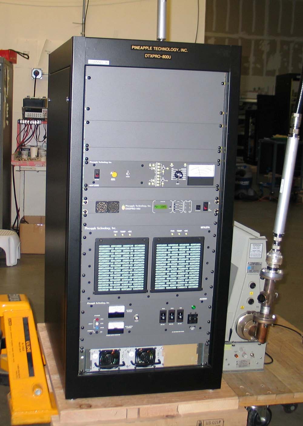
PW2DTXPRO800U
Mar 01, 2011800 W DTV TRANSMITTER
Equipment Class
TBC - Licensed Broadcast Station Transmitter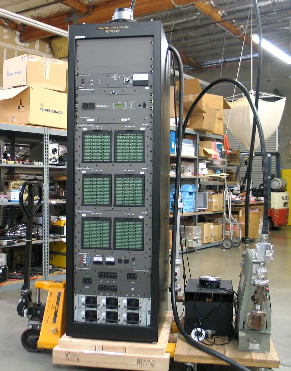
PW2DTXPRO2300U
Mar 01, 20112.3KW DTV TRANSMITTER
Equipment Class
TBC - Licensed Broadcast Station Transmitter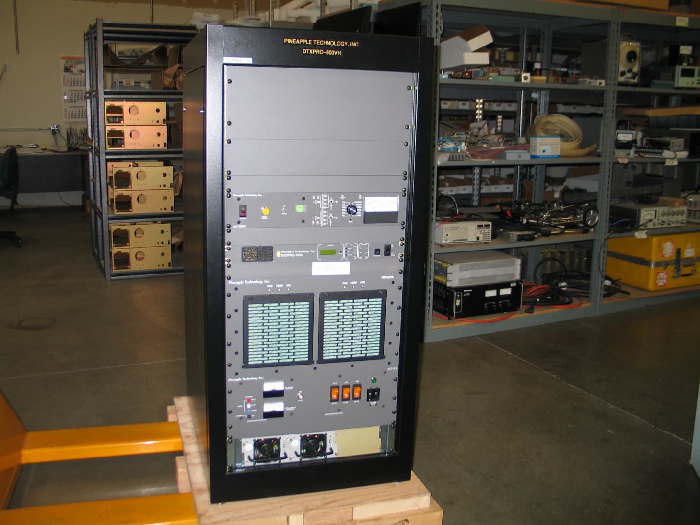
PW2DTXPRO800VH
Feb 27, 2011800 WATT DTV TRANSMITTER
Equipment Class
TBC - Licensed Broadcast Station Transmitter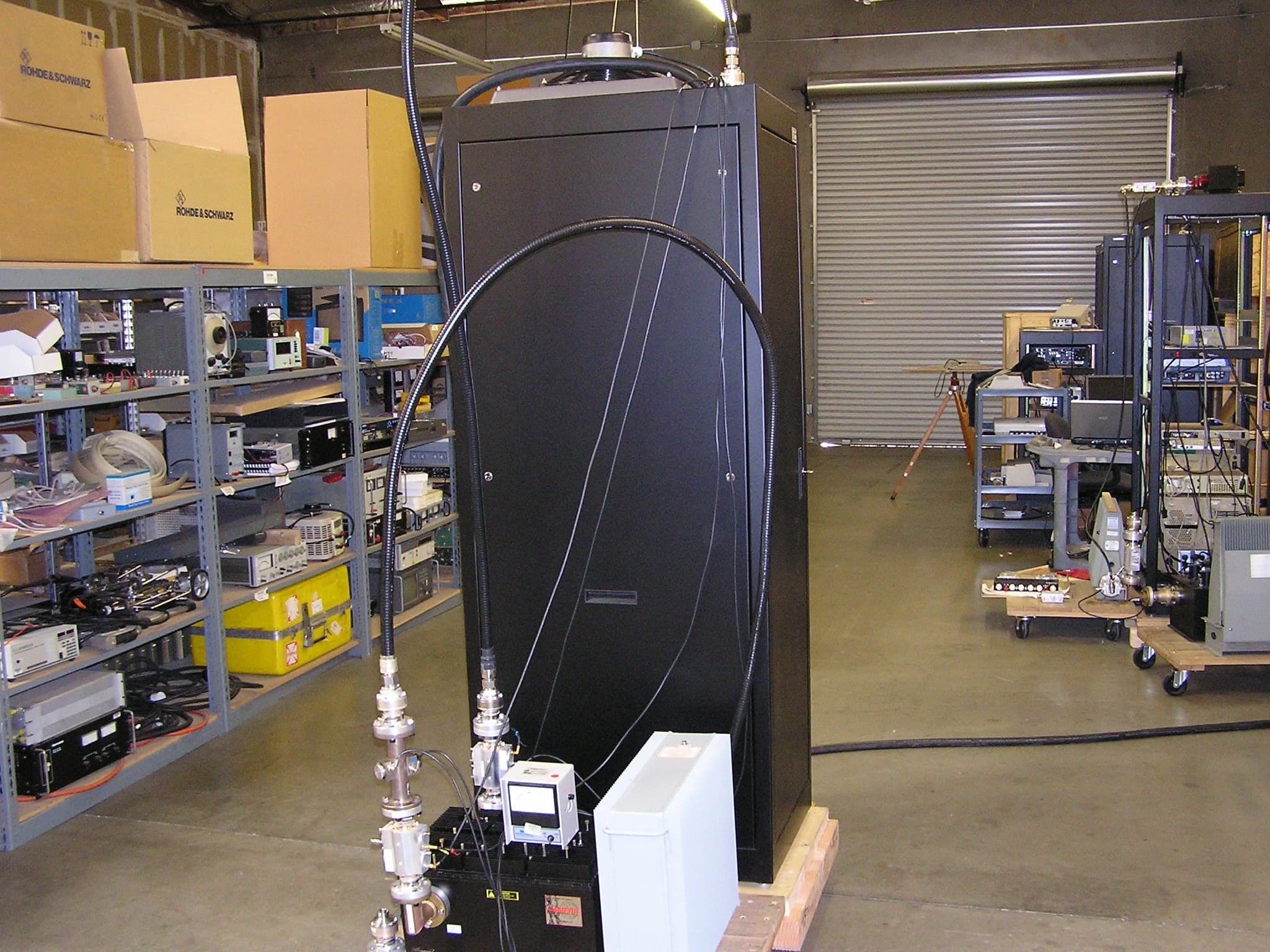
PW2DTXPRO1200U
Dec 12, 20101.2 KW DTV TRANSMITTER
Equipment Class
TBC - Licensed Broadcast Station Transmitter